CNC Joinery: How to Create Finger Joints
by RobotDictionary in Workshop > CNC
7367 Views, 38 Favorites, 0 Comments
CNC Joinery: How to Create Finger Joints


The purpose of this tutorial is to showcase a bit how a CNC machine process works from design to finished product. It is also a tutorial for more experienced users on how to create a finger joint.
Material: 3/4" sheet stock MDO (Medium Density
Overlay)
Machine: 3 axis greenBull CNC machine
Software: AutoCAD (Design), CAMBAM (Machine tools), Mach3 (Post processor)
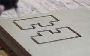
We want to show you how to make a practical joint using a CNC machine. This is a simple joint and provides a good starting point. A finger joint is a joint that has protrusions that measure the thickness of the wood, creating a flush corner when put together.
Step 1: Computer-Aided Design (CAD)
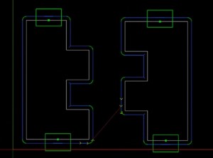
We used AutoCAD to design these pieces. The final joint is four inches wide with the fingers at one inch each.
The sheet stock we used was measured at .755 inches. It is important to compensate for the corner, so you need to go a bit farther and use .757 for all of the fingers.
Inside the design, we took the piece and rotated it 180 degrees. Then we joined all the lines to create a polygon. Next we copied it and rotated it. Normally we would put a bit of a tolerance between the finger and make it a little bit thinner, but for the time we kept it at zero to see if the wood was forgiving enough to do this, if not we would need to add a thousandths of an inch displacement.
The inside corners are not going to be perfectly square because we used a bit that is round. The bit had to do an overcut to be able to marry flat to the adjacent corner. The rounded corner also provides a relief for any stress at the corner, or stress cracks that could arise. Now that the file has been prepped, we are ready to move onto phase 2.
Step 2: Computer-Aided Manufacturing (CAM)
Open the DXF file you have just saved from the CAD program and into your CAM software. The CAM software is used to establish machining operations. Once you have the file loaded in the CAM program, select the two joints and create a roughing and a finishing profile. The roughing pass will have a clearance of .01" so that when the finishing happens, there will be only a small amount of material shaved off. We only want to have two holding tabs on these so select both and change holding tabs to a minimum of two. The roughing pass will do two passes and the finishing pass will do one. The file has now been prepped and is the part is now ready to be cut out by the CNC machine.
Step 3: CNC (Computer Numerical Control) Machine
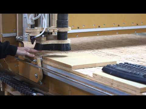
Now we are ready to cut out the joint. We zero the X, Y, and Z axes first and then run the machine. The finger joint is now complete, and there is zero tolerance, so you may want to add a little bit of tolerance to make it easier and to have glue sit in between. Another aspect of this finger joint is that these ends are perfectly flush. There is no difference between them so this worked out very well. We also put this in a vice to tighten it up a little bit more. It was able to move a little bit but not enough to make it perfectly flush, so you want to move it back about .005 of an inch.
That is how we make a finger joint with a CNC machine!