CNC Chess Piece With Autodesk Fusion360
by eamonn.lacy in Workshop > CNC
8784 Views, 63 Favorites, 0 Comments
CNC Chess Piece With Autodesk Fusion360
This project was inspired by the Advertisement-like video produced by Tormach, where the PCNC770 Lathe and Rapidturn lathe attachment are used to produce a rook. The impressive cinematics and machining shots in this video left me thinking, "how hard can it be?"
I'm fortunate enough to have access to Tormach 770M mill with a Rapidturn lathe, so that's what I used for this. most of my instructions should be similar for the 15L Slant-pro lathe or any other Tormach lathes.
This was quite a rewarding experience as it was both my first CNC Lathe cut, and the first lathe cut on my Tormach 770M after countless hours of setup and learning.
Supplies
Tormach 770M with Rapidturn lathe and appropriate cutting tools
Fusion360
Stock steel rod, I used 25mm
Step 1: Modeling the Chess Piece
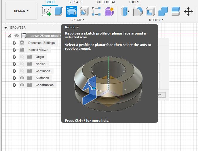
I started this project off in Fusion360, my chosen CAD package. I chose this because this is what I was taught to use, and it just happens to be perfect for this project, thanks to the integrated CAM support within the program.
the real first step was some rough sketches on paper, to get an idea of how I wanted these pieces to look. My final decision was to start off with the pawn as this was the sketch I was most pleased with. If you're following along planning to make this, I haven't included my sketches as this is less of a technical part and is more about how you want your pieces to look.
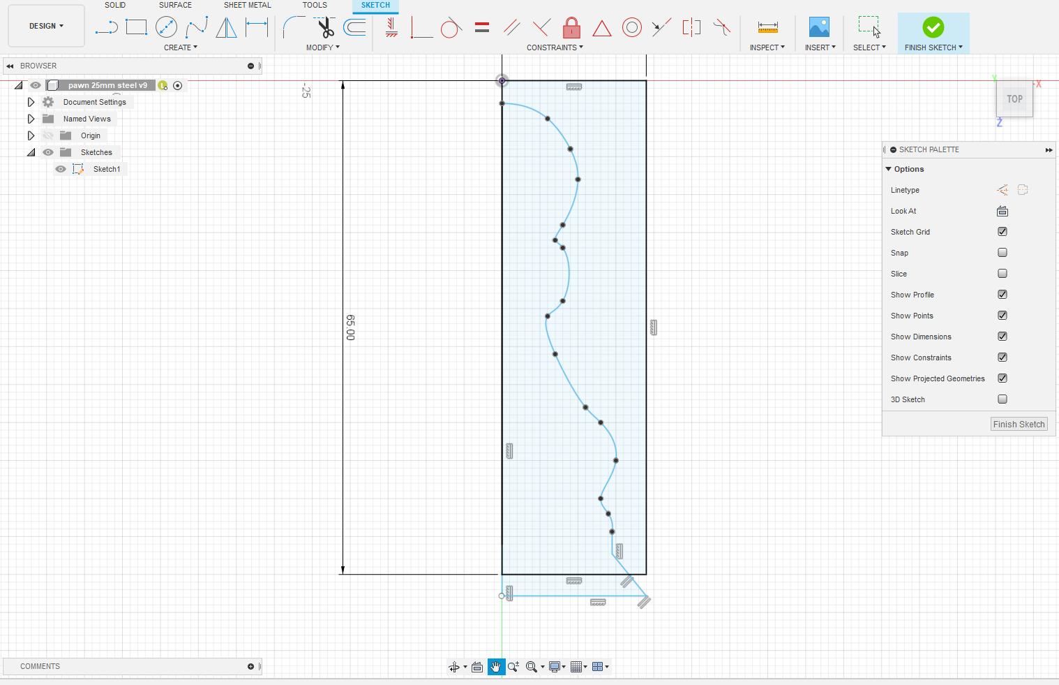
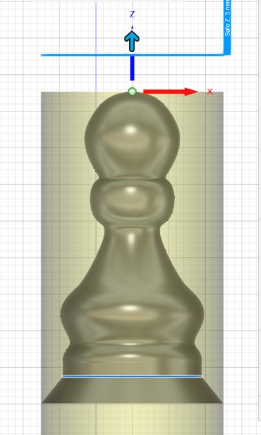
the next step was to draw the bounding box for the limit of the size, this is important and it will help ensure you can actually fit the solid inside the stock you have. In my case, I have a 90mm Bar of 25mm diameter steel. based on the rough ratio from my sketch, I decided to make my piece 36mm tall. As I'm going to use a revolved profile to produce the solid, ill make my bounding box 36x12.5mm. this gives you an area to limit your sketch to.
After this, it was time to used the line tool and fit point spline tool to produce half the profile of the chess piece. this is important because we will be revolving about the central axis of the sketch to create a solid. Although I didn't do this, one option would be to add an image of your paper sketch and follow it with the spline tool. Once I was happy with how the sketch looked, I added a relief taper on the base to reduce the cutter load in the machining stage, this is because there was a large difference in the diameter of the base of my piece in comparison to the diameter of the stock.
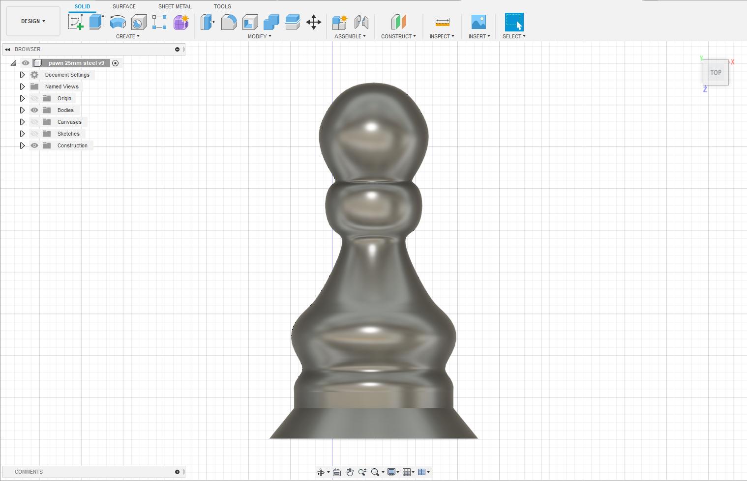
once finished the taper and sketch, revolved it. I did this by selecting the centerline on the left side of my bounding box to be the revolving axis and revolving it 360 degrees to create the piece.
It is important to consider the shape of your insert when designing, Eg, a 55-degree insert will not be able to cut a 10-degree bend or corner, your design may need to be altered.
Step 2: CAM Set-Up
Now that we have a solid, we can begin to generate the tool paths. I did this in the built-in CAM environment within fusion360. For Tormach lathes, the Z-axis is the rotational axis, e.g the axis that runs through the center of the stock, and the X-axis is the Up/down the axis of the tool post. Not all lathes are the same so this is something to keep in mind during the setup process.
I began this stage by creating a new setup in the top menu and working my way through the boxes as shown below. This can also be seen when the attached example fusion file is opened in the manufacturing environment.
Operation: Turning or Mill turning
spindle: Primary spindle
The next set of inputs will be specific to your machine, these are the coordinates that the machine will read.
Orientation: Z-axis select (rail on the base of the chess piece)
Z-axis pointing out of the top of the chess piece
Origin: stock front
Safe Z: 5mm
Model: body selected
Spun profile: checked
chuck: stock back
Stock
the next bit is the stock setup, this will be based on the material you have and the scale of your piece but its fairly self-explanatory.
Model position: offset from the front
and that's the end of the setup!
Downloads
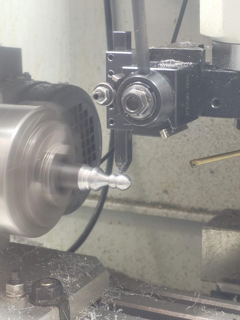
Step 3: Roughing Tool Path Generation
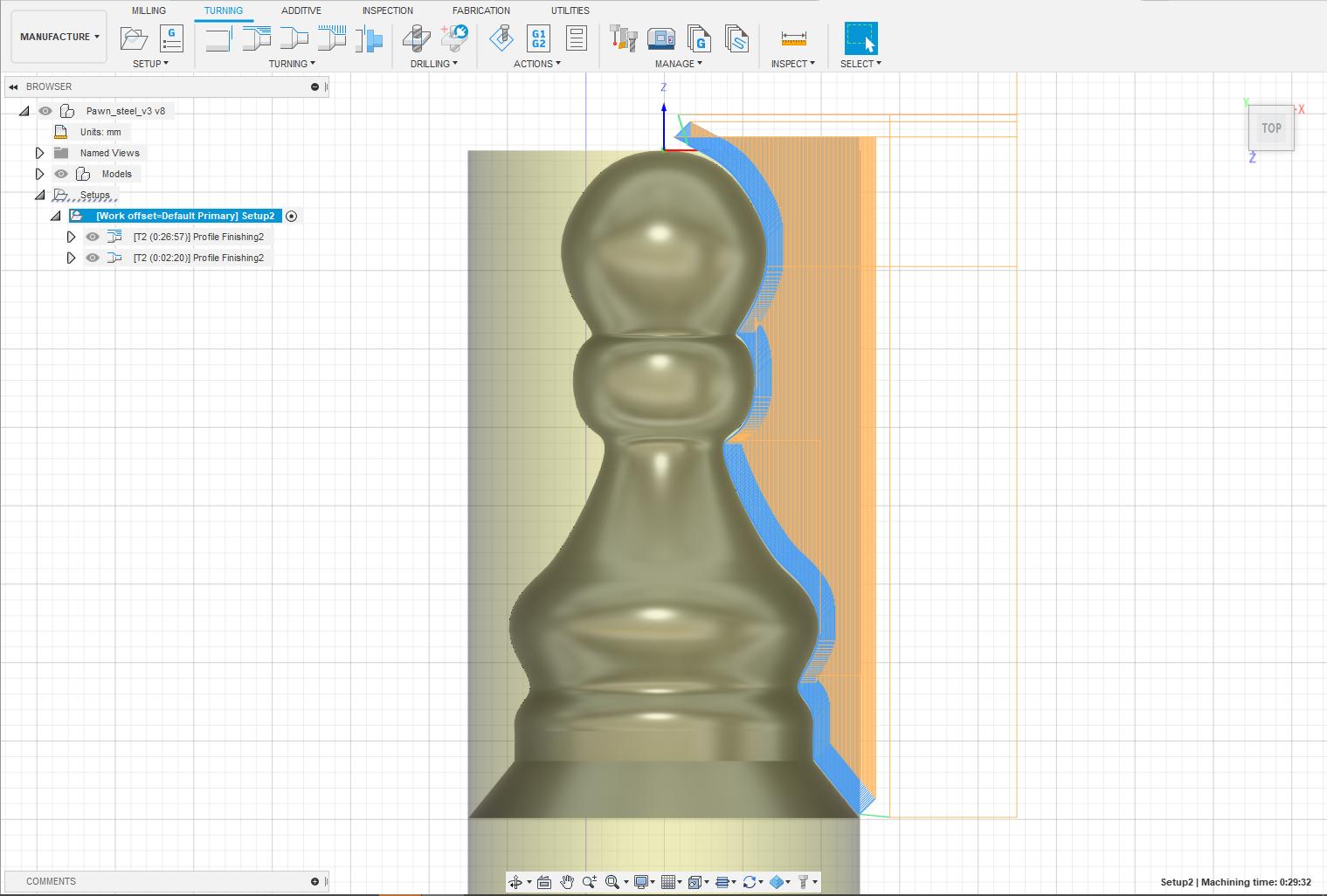
In this section, I will be focusing on the first of two main operations for this project, roughing.
Roughing consists of linear passes removing a certain amount of material on the x-height, these are the passes that do the bulk of the material removal but leave a rough finish. The settings used in both of these operations will vary massively between cutting tool, insert, and machine, so it was a bit of trial and error for me until I was happy with both the cut depth (amount of material being removed) and feed speed (speed of feed in the Z direction).
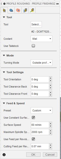
For my 55-degree carbide insert, neutral hand profiling tool, and cutting 25mm mild steel, I settled at about:
0.1mm depth of cut
0.07mm per Revolution of feed speed
as well as a material surface speed of 60 meters per minute.
for this process, I made sure to leave 0.1mm of stock remaining for the finishing pass.
lead in 0.5mm prevents the cutter from ramming into the stock.
I've attached the tool file in the link below for anyone who would like to follow along with this demo!
Step 4: Finishing Tool Path Generation
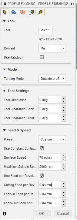
The finishing pass is a more dynamic tracing path used as a final process to level out the surface of the material. this is usually at a higher surface speed, lower feed speed, and a greatly reduced depth of cut. for this step I used the following speeds:
2 passes
0.05mm depth of cut
0.05mm per revolution feed speed
70 meters per minute surface speed
The last step after this is to look at the machine simulation on Fusion360 and see if there are any noticeable errors in the path generation, these are red lines along the timeline and will show when the machine has a collision with the stock, fusion will also give you a warning in the operation menu.
Step 5: Post Processing
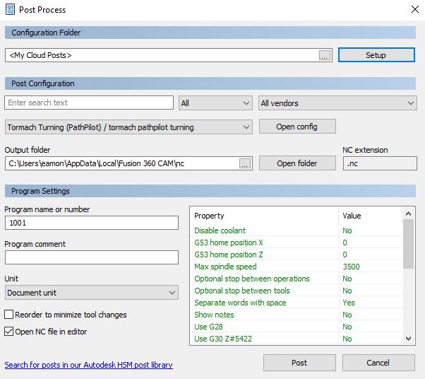
Post-processing is the process in which fusion converts the generated tool paths into machine-readable code, known as G-Code.
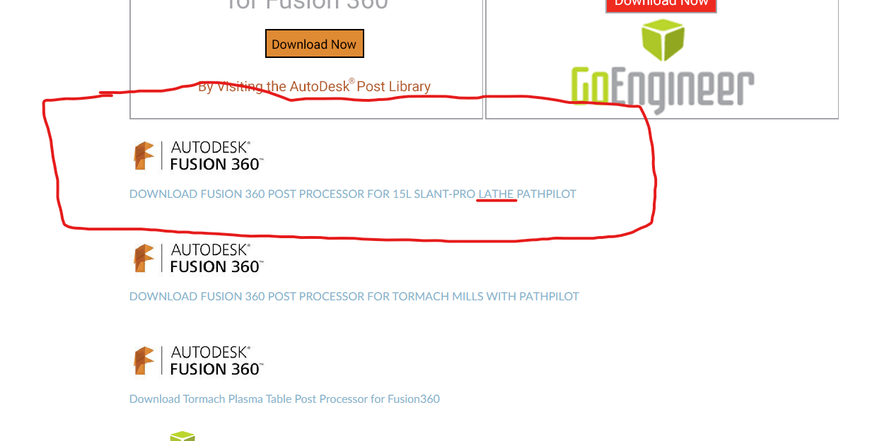
the required post-processor will be different for every machine, and possibly different depending on the operation. As we are using the lathe function, it's important that the Tormach "post-processor for turning".
I have included the link to this here. This needs to be saved to the posts folder on your computer, linked to fusion. Here is an article explaining this process.
My screenshot looks a little different as I have saved my post-processor to my Autodesk cloud folder.
The generated file should be saved as a .nc file and will contain the G-code. It is important to open this and read it to ensure it posted correctly. Once you're happy with this it can be saved to a USB.
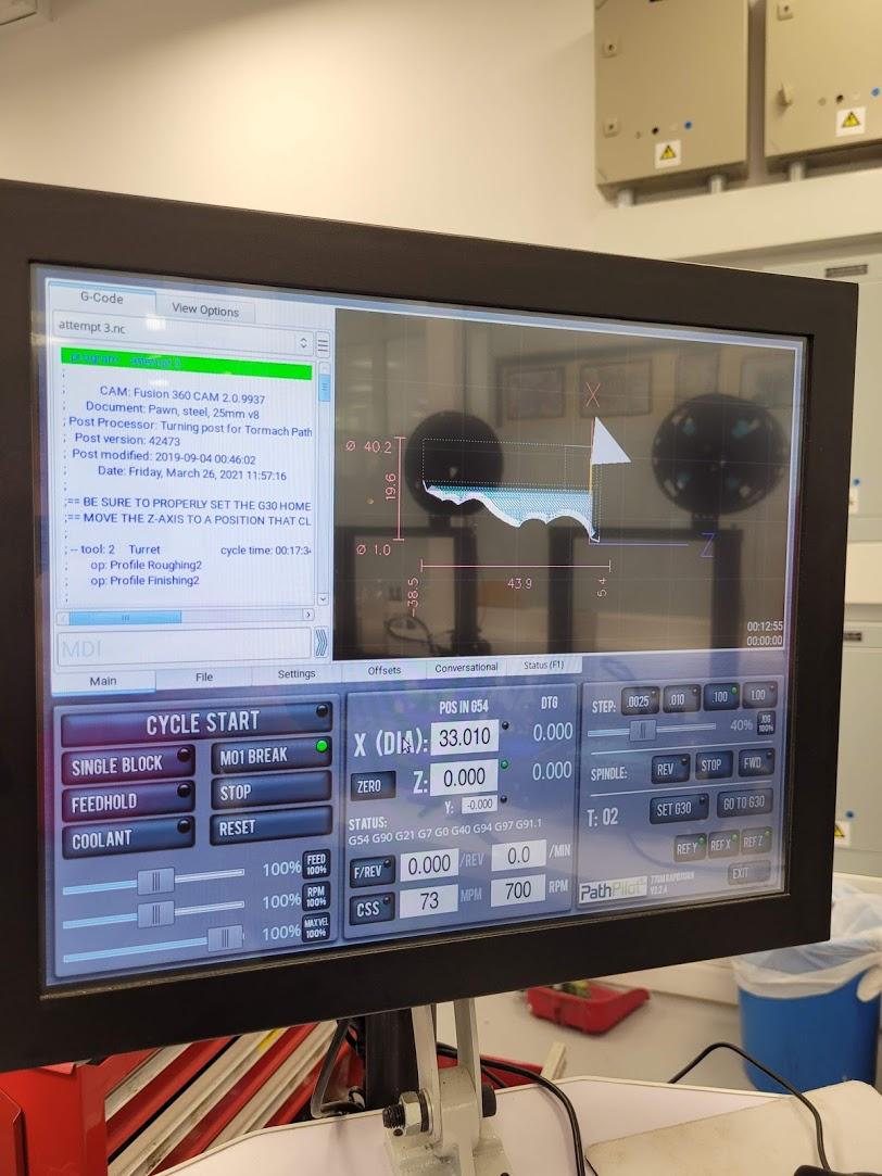
Step 6: Machine Set-up
In this step, I will be talking through the whole setup of the Tormach 770M, so if you're using a different machine feel free to skip to the next step and get your machine set up.
Power On
As the protective doors are locked by the electrical door lock, you will need to first turn the machine on at the master power (red switch) on the right-hand side of the machine enclosure. This will power on the machine and the connected console computer. Next, release the emergency stop button below the doors, (twist until it pops up) and press the blue reset button beside the E-stop, as well as the reset button on the screen. You will now be able to open the doors.
Reference
The next step is to reference the Axes of the machine, In the bottom corner of the machine, above the exit button, there are 3 buttons, REF X, REF Y, and REF Z. these will all need to be referenced in order to give the machine an idea of where is in space. Make sure the machine is clear of any components and there is no stock or cutter in the machine. Press these, one by one, until all of the buttons have green dots on them, indicating the axes have been referenced.
Transfer To Machine
the next step is to transfer the file from the USB to the machine. As I don't have any free USB slots, I temporarily unplug my shuttle Dial and plug the USB into that slot. I then navigate to the File tab on the console, this will show the machine storage on the left and the USB storage on the right. navigate to the correct folders and click copy from USB. then eject the USB and plug the shuttle dial back in. Then open the file!
Y-axis set
unless the previous user has changed it, the Y-axis should be preset, move the tool post to Y0, this can be done manually or with the command G0Y0, rapid travel. if this does not look correct it will need to be set again. this is a slightly more complex process and is explained on page 42 of the manual better than I could explain it. however, this should not have to be done every time as it is not dependant on the stock, and on the Tormach I use, I have adjusted the manual setting screw on the tool older so all of the Y0 points match between tool changes.
Stock setup
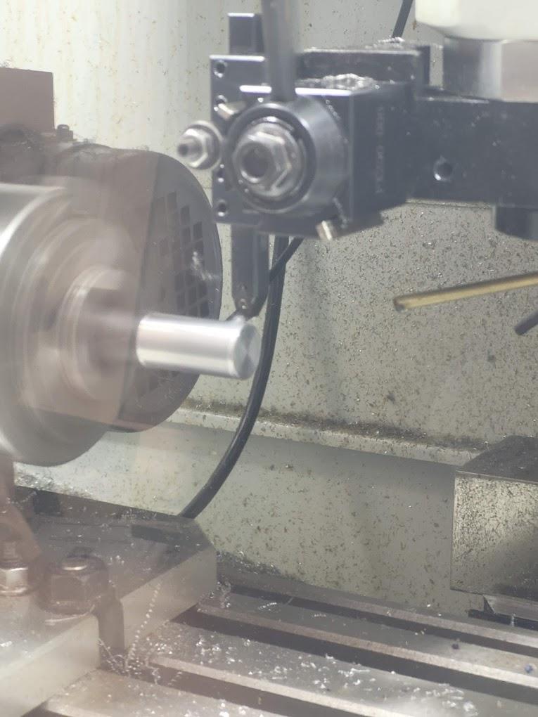
it's important that you have the correct length of stock, so check in your fusion setup that you have the correct diameter and length of material. It will also speed up the process if the stock is manually faced off to get a flat reference point for the Y-axis. Make sure this is properly secured in the chuck of the lathe as if this comes out, it won't be a pretty accident. Take a moment to remove any deflection (wiggle up and down) in the stock when it turns, this will impact how it turns, so the minimal this is, the better.
Z-Axis set
I usually do this at the same time I face off the stock, as I use the right-hand tool and manually control the tool post to face off the stock. To do this, I check the stock and tool are secure and set a speed of around 200rpm to test the spindle. After I'm happy with my test, I turn the speed up to about 700rpm and face off using the right-hand cutting tool and the manual control dial. once I have faced off the stock, retraced the tool in the X direction, and turned off the spindle. I will set the Z-axis value to 6.72, I know this because I have measured the difference between the tool I plan to use for my operation, and the tool that I have just used to face off. this means that the new Y0 value will match the alignment of the neutral hand tool I want to use and then the end of the stock.
X-Axis set
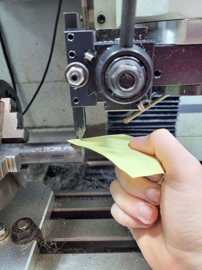
as shown in the picture above, I like to use a post-it note to set the x-axis. Move the tool you want to use for the operation above the stock and slowly lower it until you are nearly in contact. Hold a post-it note between the stock and the cutter and step it down in decreasing increments until you can feel the tool grabbing the post-it note, but not pinning it in place. once this is in place, set the X(DIA) value to the diameter of the stock material. This is because the machine in reading in diameter increment, meaning double the distance from the surface of the material to the center of the rotational axis. This will give the machine an idea of where the rotational axis is relative to the cutting tool. this value should be the same value for the stock diameter in the fusion360 setup. Once this is set, take care to retract the tool in the correct direction (up) as moving it down further could damage the stock and machine.
Final check
To double-check these values by manually moving to the 0 points and checking it seems right, X 0 should be the center of the stock on the rotating axis, and Z0 should be the end of the stock.
On the console screen, you should be able to see the cutting tool with a yellow tracing line showing where it is. check if this makes sense based on the values you have set, eg if the cutting tool on the screen is miles away from the tool paths while the machine is just above it, it's probably wrong.
Step 7: the Cut
On the door of my machine, I have a precut checklist of the things I like to check before I cut.
E-Stop off?
Axes Set correctly?
Compressor on (coolant spray)?
RPM in code correct?
correct feed?
correct stock length?
are tool and stock secure?
is the door closed?
Is single block mode on?
(this is important for new code as it lets you verify the machine is doing what you want it to do at each step along the way, once you're happy with the first pass you can turn this off)
Max Vel set to 4%
( this is important as it gives you time to react if the machine moves in a direction you don't want it to, as the rapid travel speed is only 4% of the maximum, again this can be turned off after the first pass)
decreased RPM and feed for the first pass?
(less important but I like to do this)
Once this is all done, hit cycle start.
Step 8: Finishing Touches
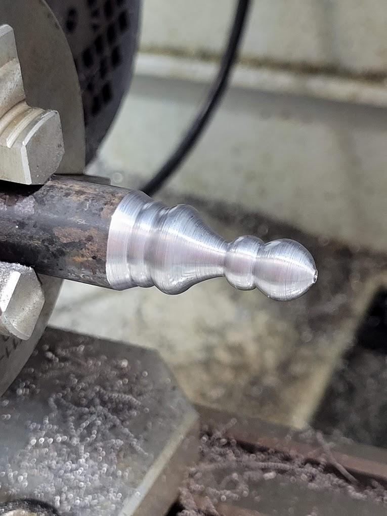
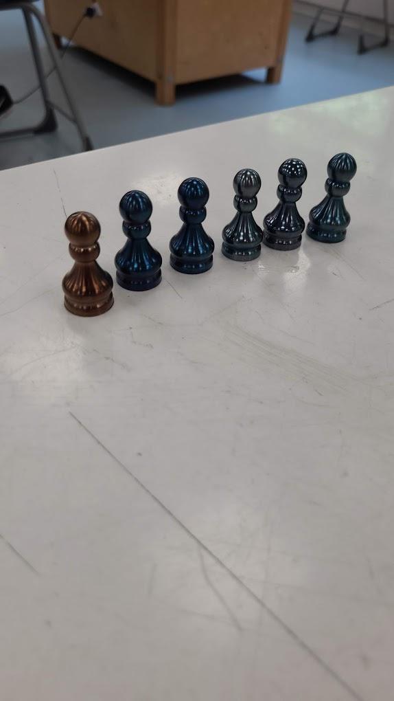
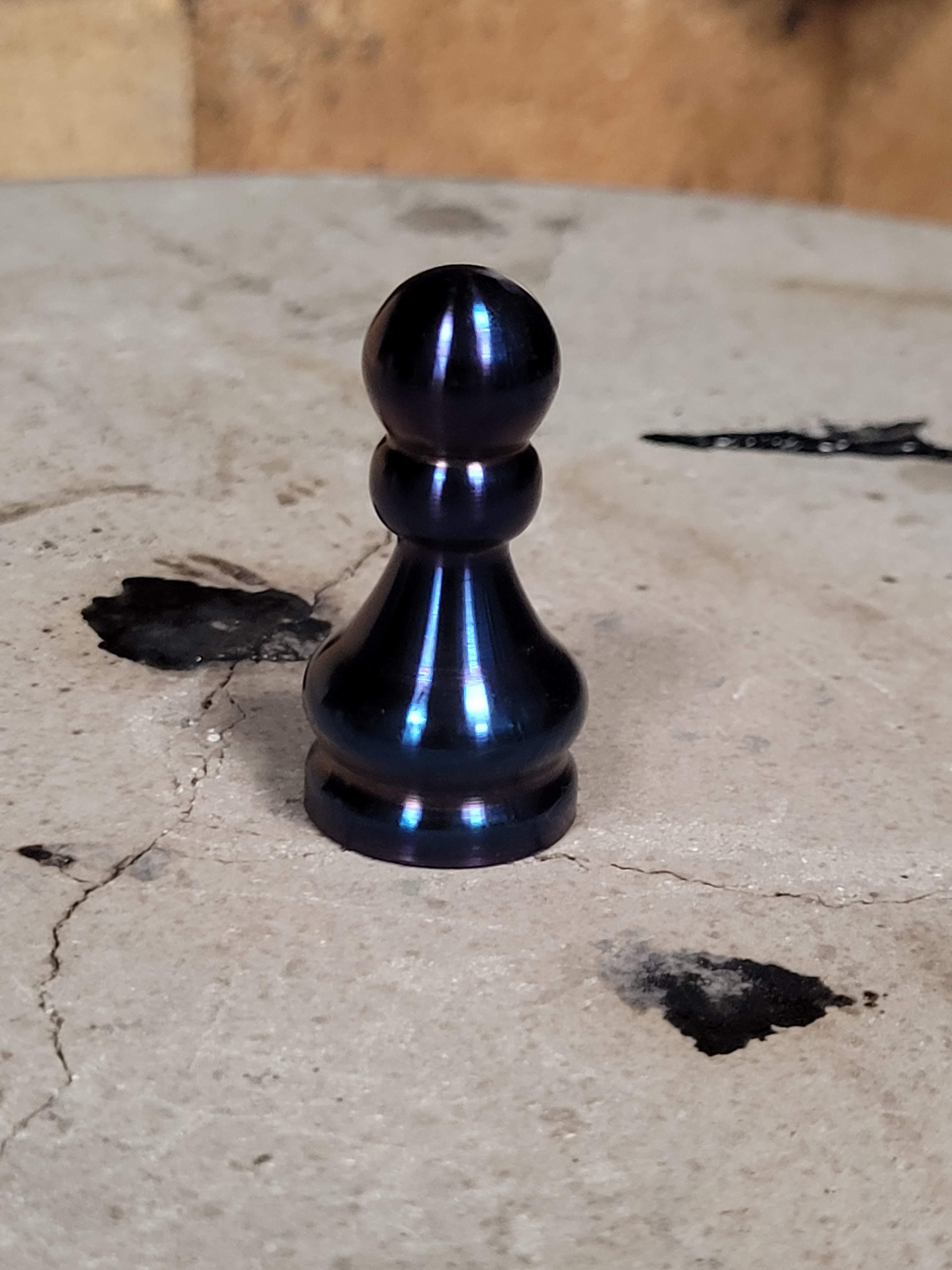
Hopefully, that last step went smoothly, and you now have your machined chess piece attached to the stock. As I don't have a parting tool so I do this step manually on another lathe, as well as polishing the chess piece.
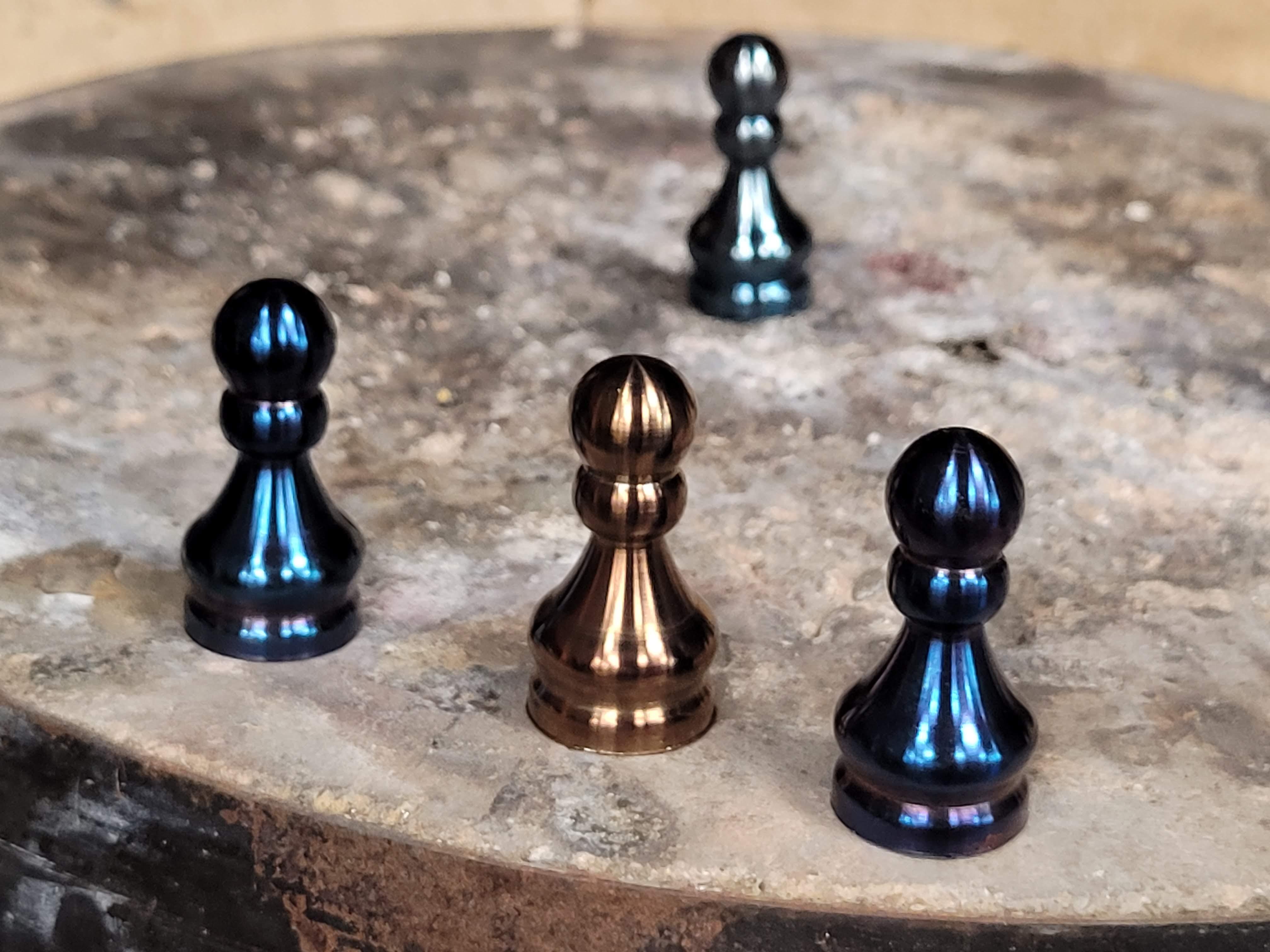
Although my settings weren't perfect, it wasn't anything a bit of sandpaper and polish couldn't fix!
I added a final step of thoroughly cleaning the chess pieces in alcohol and testing some different tempering finishes, based on a chart I found online.
Hope you enjoyed it!