CAN Communication Bus Between TIVA-C and Nodemcu
by abdulrahman_yasser in Circuits > Microcontrollers
843 Views, 1 Favorites, 0 Comments
CAN Communication Bus Between TIVA-C and Nodemcu

This is an application to test Controlled Area Network (CAN) bus communication. The communication bus is between two ECUs, Tiva-c and Nodemcu.Github Link
You may also check that Github link, it'd be helpful for your Tiva-C CAN module programming
This is an application on CAN Communication Bus. It doesn’t Explain how CAN works.
The Controller Area Network (CAN bus) is a message-based protocol designed to allow the Electronic Control Units (ECUs) found in today’s automobiles, as well as other devices, to communicate with each other in a reliable, priority-driven fashion
In I2C Communication protocol you start the communication by sending the Address of the Device and then the Data.
In CAN it’s a little different, you send a message, and that message contains the follows : Message Data — Message ID — Error Checking — other Configurations bits.
So the module that Receives the message is the module that needs that message ID, and already programmed to catch that message ID and receive it.
A message could be received by more than one module.
Nodemcu is connected to a module called MCP2515
MCP2515 is a stand-alone Controller Area Network (CAN) controller that implements the CAN specification, Version 2.0B. It is capable of transmitting and receiving both standard and extended data and remote frames. The MCP2515 has two acceptance masks and six acceptance filters that are used to filter out unwanted messages, thereby reducing the host MCU’s overhead
MCP2515 interfaces with microcontrollers (MCUs) via an industry standard Serial Peripheral Interface (SPI)
TIVA-C is connected to a module called MCP2551
Typically, each node in a CAN system must have a device to convert the digital signals generated by a CAN controller to signals suitable for transmission over the bus cabling (differential output). It also provides a buffer between the CAN controller and the high-voltage spikes that can be generated on the CAN bus by outside sources (EMI, ESD, electrical transients, etc.).
MCP2515 interfaces with microcontrollers (MCUs) via an industry standard Serial Peripheral Interface (SPI)
Nodemcu application
- Nodemcu transmits 8 data bytes, all bytes has the same value, either 1s or 0s.
- Nodemcu transmits 8 bytes of 1s or 0s to Tiva-c.
- Each transmission has a 500ms delay, it transmits total of 12 transmission.
- After the 12 transmission are done, it starts receiving from Tiva-c.
- After receiving 6 messages, it will go to step one again.
Tiva-c application
- Tiva-c's code works only on interrupt.
- An interrupt when it receives data, which rise up a flag to read the data.
- An Interrupt when the data is completely transmitted.
- On-board button interrupt which rise up a flag to transmits data.
Supplies
.jpeg)


MCP2551 - MCP2515 - Nodemcu - Tiva-c
Circuit
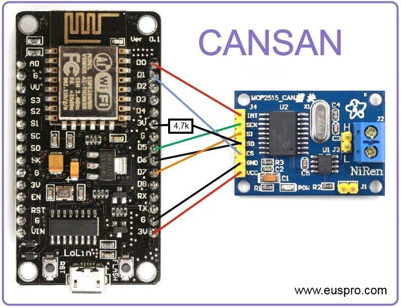

- First we wire up the Nodemcu with MCP2515.
- Make sure that MCP2515 requires 5 volt.
- Install the MCP2551 in the Tiva-c
- Wire CANH with CANL
Nodemcu Code
First in Nodemcu we will use the library in the link.
- we are using SPI because MCP2515 interacts with Nodemcu via SPI
- The code first Loops 6 times
- Transmits 8 bytes, all the bytes data are 0x01
- Delay for 500ms
- Transmits 8 bytes, all the bytes data are 0x00
- Delay for 500m
Here we expect Tiva-c to change it's action every 500ms
- The code Loops again 6 times
- wait until there are data to receive
Here we expect the Nodemcu will receive 6 messages
// CAN Send Example
//


#include <mcp_can.h>
#include <SPI.h>


long unsigned int rxId;
unsigned char len = 0;
unsigned char rxBuf[8];
char msgString[128];                        // Array to store serial string


#define CAN0_INT 16                              // Set INT to pin 2
MCP_CAN CAN0(5);     // Set CS to pin 10


void setup()
{
  Serial.begin(115200);


  // Initialize MCP2515 running at 16MHz with a baudrate of 500kb/s and the masks and filters disabled.
  if(CAN0.begin(MCP_ANY, CAN_500KBPS, MCP_16MHZ) == CAN_OK) Serial.println("MCP2515 Initialized Successfully!");
  else Serial.println("Error Initializing MCP2515...");


  CAN0.setMode(MCP_NORMAL);   // Change to normal mode to allow messages to be transmitted


  pinMode(CAN0_INT, INPUT);                            // Configuring pin for /INT input


}
byte i = 0;
byte data_1[8] = {1, 1, 1, 1, 1, 1, 1, 1};
byte data_0[8] = {0, 0, 0, 0, 0, 0, 0, 0};


void loop()
{
  byte sndStat;
  byte i;
  for(i = 0; i < 6; i++){
    // send data:  ID = 0x100, Standard CAN Frame, Data length = 8 bytes, 'data' = array of data bytes to send
    sndStat = CAN0.sendMsgBuf(0x23, 8, data_1);


    if(sndStat == CAN_OK){
      Serial.println("Message Sent Successfully and received !");
    } else {
      Serial.println("Error Sending Message...");
    }
    delay(500);   // send data per 100ms
    // send data:  ID = 0x100, Standard CAN Frame, Data length = 8 bytes, 'data' = array of data bytes to send
    sndStat = CAN0.sendMsgBuf(0x23, 8, data_0);


    if(sndStat == CAN_OK){
      Serial.println("Message Sent Successfully and received !");
    } else {
      Serial.println("Error Sending Message...");
    }
    delay(500);   // send data per 100ms
  }


  for(i = 0; i < 6; i++){
    while(digitalRead(CAN0_INT));
    if(!digitalRead(CAN0_INT))                         // If CAN0_INT pin is low, read receive buffer
    {
      CAN0.readMsgBuf(&rxId, &len, rxBuf);      // Read data: len = data length, buf = data byte(s)

      if((rxId & 0x80000000) == 0x80000000)     // Determine if ID is standard (11 bits) or extended (29 bits)
        sprintf(msgString, "Extended ID: 0x%.8lX  DLC: %1d  Data:", (rxId & 0x1FFFFFFF), len);
      else
        sprintf(msgString, "Standard ID: 0x%.3lX       DLC: %1d  Data:", rxId, len);

      Serial.print(msgString);

      if((rxId & 0x40000000) == 0x40000000){    // Determine if message is a remote request frame.
        sprintf(msgString, " REMOTE REQUEST FRAME");
        Serial.print(msgString);
      } else {
        for(byte i = 0; i<len; i++){
          sprintf(msgString, " 0x%.2X", rxBuf[i]);
          Serial.print(msgString);
        }
      }

      Serial.println();
    }
  }


}
/*********************************************************************************************************
  END FILE
*********************************************************************************************************/
Tiva-c Code
Tiva-c's code is divided in three parts,
- main application
- Static CAN folder
- Dynamic CAN folder
As we said earlier, the main application on Tiva-c only works on interrupts.
- main application
so in the main code we will have only flag checking, which determine whether the desired interrupt happened or not
- Checking receive interrupt. We change the action depending on the received data
        if(g_bRXFlag_RX7 == 1){
            g_bRXFlag_RX7 = 0;
            CANMessageGet(CAN0_BASE, 7, &RxMsg, 0);
            if(RxMsg.pui8MsgData[0] == 0){
                GPIOPinWrite(GPIO_PORTF_BASE, GPIO_PIN_1, 0);
                GPIOPinWrite(GPIO_PORTF_BASE, GPIO_PIN_2, GPIO_PIN_2);
                GPIOPinWrite(GPIO_PORTF_BASE, GPIO_PIN_3, 0);
            }else if(RxMsg.pui8MsgData[0] == 0){
                GPIOPinWrite(GPIO_PORTF_BASE, GPIO_PIN_1, GPIO_PIN_1);
                GPIOPinWrite(GPIO_PORTF_BASE, GPIO_PIN_2, 0);
                GPIOPinWrite(GPIO_PORTF_BASE, GPIO_PIN_3, 0);
            }
        }
b. Checking whether the on-board button has been pressed or not
        if(g_bTransmitNow == true){
            g_bTransmitNow = false;
            CAN_MsgSend(6, 0x33, my_Tx_Data, 8);
            for(j = 0; j < 100; j++);
        }
c. Checking data is completely transmitted. If though, we will change the data for the next transmission
        if(g_bRXFlag_TX6 == 1){
            g_bRXFlag_TX6 = 0;
            my_Tx_Data[0] = i++;
            my_Tx_Data[1] = i++;
            my_Tx_Data[2] = i++;
            my_Tx_Data[3] = i++;
            my_Tx_Data[4] = i++;
            my_Tx_Data[5] = i++;
            my_Tx_Data[6] = i++;
            my_Tx_Data[7] = i++;
        }
2 Dynamic part
There are two containers need to be pre-configured before the code is build.
This part should be reconfigured be the user to fit his application.
a. CAN module Container
const CANConfig_t CANConfigs[] = {
                                  {.CAN_ON_OFF =1,
                                   .BaudRate = 125000,
                                   .CAN_Base=CAN0_BASE_e,
                                   .CAN_Interrupts = CAN_INT_MASTER | CAN_INT_ERROR | CAN_INT_STATUS},

                                   {.CAN_ON_OFF =0,
                                    .BaudRate = 125000,
                                    .CAN_Base=CAN1_BASE_e,
                                    .CAN_Interrupts = CAN_INT_MASTER | CAN_INT_ERROR | CAN_INT_STATUS}

};
b. CAN messages container
CANConfigMsgs_t CANMsgConfigs[] = {
                                       {
                                        .CAN_Base = CAN0_BASE_e,
                                        .Msg_ID = 6,
                                        .flags = MSG_OBJ_TYPE_TX,
                                        .Msg =
                                        {
                                        .ui32MsgID = 0x33,
                                        .ui32MsgIDMask = 0xff,
                                        .ui32MsgLen = 8,
                                        .ui32Flags = MSG_OBJ_TX_INT_ENABLE | MSG_OBJ_USE_ID_FILTER
                                        }
                                       },
                                        {
                                         .CAN_Base = CAN0_BASE_e,
                                         .Msg_ID = 7,
                                         .flags = MSG_OBJ_TYPE_RX,
                                         .Msg =
                                         {
                                         .ui32MsgID = 0x23,
                                         .ui32MsgIDMask = 0xff,
                                         .ui32MsgLen = 8,
                                         .ui32Flags = MSG_OBJ_RX_INT_ENABLE | MSG_OBJ_USE_ID_FILTER
                                         }
                                       }
};
3 Static part
You shouldn't change that part unless you know what are you doing.
a. CAN Message Initialization function
void CAN_MsgInint(CANConfigMsgs_t* myConfigs){
    int i;
    for(i = 0; i < NUMBER_OF_INITIALIZED_CAN_MESSAGES; i++ ){
        if(myConfigs[i].CAN_Base == CAN0_BASE_e){
            CANMessageSet(CAN0_BASE, myConfigs[i].Msg_ID, &myConfigs[i].Msg, myConfigs[i].flags);
        }else if(myConfigs[i].CAN_Base == CAN1_BASE_e){
            CANMessageSet(CAN1_BASE, myConfigs[i].Msg_ID, &myConfigs[i].Msg, myConfigs[i].flags);
        }
    }
}
b. CAN module Initialization function
void CAN_my_Init(CANConfig_t* myConfigs){
    int i;
    for(i = 0; i < NUMBER_OF_CAN_CHANNELS; i++ ){
        if(myConfigs[i].CAN_ON_OFF == 0){
            continue;
        }
        if(myConfigs[i].CAN_Base == CAN0_BASE_e){

            /*
            * PORT's PIN Initialization
            */

            SysCtlPeripheralEnable(SYSCTL_PERIPH_GPIOB);

            while(!SysCtlPeripheralReady(SYSCTL_PERIPH_GPIOB));

            GPIOPinConfigure(GPIO_PB4_CAN0RX);
            GPIOPinConfigure(GPIO_PB5_CAN0TX);

            GPIOPinTypeCAN(GPIO_PORTB_BASE, GPIO_PIN_4 | GPIO_PIN_5);

            /*
             * CAN module Initialization
             */

            SysCtlPeripheralEnable(SYSCTL_PERIPH_CAN0);

            CANInit(CAN0_BASE);
            CANBitRateSet(CAN0_BASE, SysCtlClockGet(), myConfigs[i].BaudRate);

            CANIntEnable(CAN0_BASE, myConfigs[i].CAN_Interrupts);
            CANIntRegister(CAN0_BASE, CANIntHandler);
            IntEnable(INT_CAN0);
            CANEnable(CAN0_BASE);

        }else if(myConfigs[i].CAN_Base == CAN1_BASE_e){

            /*
            * PORT's PIN Initialization
            */

            SysCtlPeripheralEnable(SYSCTL_PERIPH_GPIOA);

            while(!SysCtlPeripheralReady(SYSCTL_PERIPH_GPIOA));

            GPIOPinConfigure(GPIO_PA0_CAN1RX);
            GPIOPinConfigure(GPIO_PA1_CAN1TX);

            GPIOPinTypeCAN(GPIO_PORTA_BASE, GPIO_PIN_0 | GPIO_PIN_1);

            /*
             * CAN module Initialization
             */

            SysCtlPeripheralEnable(SYSCTL_PERIPH_CAN1);

            CANInit(CAN1_BASE);
            CANBitRateSet(CAN1_BASE, SysCtlClockGet(), myConfigs[i].BaudRate);

            CANIntEnable(CAN1_BASE, myConfigs[i].CAN_Interrupts);
            CANIntRegister(CAN1_BASE, CANIntHandler);
            IntEnable(INT_CAN1);
            CANEnable(CAN1_BASE);

        }
    }

}
c.CAN Message Send (Not necessary and can use the original one)
void CAN_MsgSend(uint8_t ObjID, uint8_t MsgID, uint8_t* data, uint8_t len){
    tCANMsgObject original;
    CANConfigMsgs_t* myMsg;
    myMsg = CAN_getMsgConfigSpecificMsg(ObjID);

    if(myMsg->flags != MSG_OBJ_TYPE_TX){
        return;
    }

    original.pui8MsgData = myMsg->Msg.pui8MsgData;
    original.ui32Flags = myMsg->Msg.ui32Flags;
    original.ui32MsgID = myMsg->Msg.ui32MsgID;
    original.ui32MsgIDMask = myMsg->Msg.ui32MsgIDMask;
    original.ui32MsgLen = myMsg->Msg.ui32MsgLen;

    myMsg->Msg.pui8MsgData = data;
    myMsg->Msg.ui32MsgLen = len;
    myMsg->Msg.ui32MsgID = MsgID;

    if(myMsg->CAN_Base == CAN0_BASE_e){
        CANMessageSet(CAN0_BASE, myMsg->Msg_ID, &myMsg->Msg, myMsg->flags); // send as msg object 1
    }else if(myMsg->CAN_Base == CAN1_BASE_e){
        CANMessageSet(CAN1_BASE, myMsg->Msg_ID, &myMsg->Msg, myMsg->flags); // send as msg object 1
    }

    myMsg->Msg.pui8MsgData = original.pui8MsgData;
    myMsg->Msg.ui32Flags = original.ui32Flags;
    myMsg->Msg.ui32MsgID = original.ui32MsgID;
    myMsg->Msg.ui32MsgIDMask = original.ui32MsgIDMask;
    myMsg->Msg.ui32MsgLen = original.ui32MsgLen;
}
d. CAN Message Get (original function by Ti-ware)
CANMessageGet(CAN0_BASE, MsgID, psMssgObject, bClrPendingInt);
Lastly the GPIO part to initialize the on-board LEDs and on-board buttons.
void SystemInit(void){
    SysCtlClockSet(SYSCTL_SYSDIV_1 | SYSCTL_USE_OSC | SYSCTL_OSC_MAIN | SYSCTL_XTAL_8MHZ);


    SysCtlPeripheralEnable(SYSCTL_PERIPH_GPIOF);

    /* Check if the peripheral access is enabled. */
    while(!SysCtlPeripheralReady(SYSCTL_PERIPH_GPIOF))
    {
    }


    GPIOPinTypeGPIOOutput(GPIO_PORTF_BASE, GPIO_PIN_1 | GPIO_PIN_2 | GPIO_PIN_3);
    /* Set GPIO_PORTF_BASE, GPIO_PIN_1 high */
    GPIOPinWrite(GPIO_PORTF_BASE, GPIO_PIN_1, GPIO_PIN_1);


    HWREG(GPIO_PORTF_BASE+GPIO_O_LOCK) = GPIO_LOCK_KEY;
    HWREG(GPIO_PORTF_BASE+GPIO_O_CR) |= GPIO_PIN_0;
    GPIOPinTypeGPIOInput(GPIO_PORTF_BASE, GPIO_PIN_0 | GPIO_PIN_4);
    GPIOPadConfigSet(GPIO_PORTF_BASE, GPIO_PIN_0 | GPIO_PIN_4, GPIO_STRENGTH_12MA, GPIO_PIN_TYPE_STD_WPU);
    GPIOIntTypeSet(GPIO_PORTF_BASE, GPIO_PIN_0 | GPIO_PIN_4, GPIO_FALLING_EDGE);
    GPIOIntEnable(GPIO_PORTF_BASE, GPIO_PIN_0 | GPIO_PIN_4);

    /* enable interrupt to portf */
    IntEnable(INT_GPIOF);

}
Tiva-c Interrupt Handlers
Last thing we need to mention the Interrupt handler, which manipulate and change the flags in the main application

1- GPIO Interrupt Service Routine

void GPIOFIntHandler(void)
{
    /*check if interrupt is by SW1*/
    if (GPIOIntStatus(GPIO_PORTF_BASE,0) & GPIO_PIN_4)
    {
        GPIOIntClear(GPIO_PORTF_BASE, GPIO_PIN_4);
        g_bTransmitNow = true;
    }
    /* check if interrupt causes by PF0/SW2 */
    else if (GPIOIntStatus(GPIO_PORTF_BASE,0) & GPIO_PIN_0)
    {
        GPIOIntClear(GPIO_PORTF_BASE, GPIO_PIN_0);
        g_bTransmitNow = true;
    }
    else
    {
        /*do nothing*/
    }
}


2- CAN Interrupt Service Routine

void CANIntHandler(void)
{
    uint32_t ui32Status;  /* Declare a variable to store interrupt status. */


    /* Read the CAN interrupt status to find the cause of the interrupt. */
    ui32Status = CANIntStatus(CAN0_BASE, CAN_INT_STS_CAUSE);


    /* If the cause is a controller status interrupt, then get the status. */
    if (ui32Status == CAN_INT_INTID_STATUS) {
        /* Read the controller status. This will return a field of status
         * error bits that can indicate various errors. Error processing
         * is not done in this example for simplicity. Refer to the
         * API documentation for details about the error status bits.
         * The act of reading this status will clear the interrupt. If the
         * CAN peripheral is not connected to a CAN bus with other CAN devices
         * present, then errors will occur and will be indicated in the
         * controller status.
         */
        ui32Status = CANStatusGet(CAN0_BASE, CAN_STS_CONTROL);


        /* Set a flag to indicate some errors may have occurred. */
        g_bErrFlag = 1;
    }else{


    /* Check if the cause is message object 1, which is what we are using for
     * sending messages.
     */

        switch(ui32Status){
        case 6:
          /* Getting to this point means that the TX interrupt occurred on
           * message object 6, and the message TX is complete. Clear the
           * message object interrupt.
           */
          CANIntClear(CAN0_BASE, 6);


          g_ui32MsgCount++;
          g_bRXFlag_TX6 = 1;


          /* Increment a counter to keep track of how many messages have been
           * sent. In a real application, this could be used to set flags to
           * indicate when a message is sent.
           */


          /* Since the message was sent, clear any error flags. */
          g_bErrFlag = 0;
          break;


        case 7:
          /* Getting to this point means that the RX interrupt occurred on
           * message object 7, and the message RX is complete. Clear the
           * message object interrupt.
           */
          CANIntClear(CAN0_BASE, 7);


          g_ui32MsgCount++;
          g_bRXFlag_RX7 = 1;


          /* Increment a counter to keep track of how many messages have been
           * sent. In a real application, this could be used to set flags to
           * indicate when a message is sent.
           */


          /* Since the message was sent, clear any error flags. */
          g_bErrFlag = 0;
          break;


        default:
          /* Spurious interrupt handling can go here.
           * This part is executed when an unexpected interrupt occurs,
           * which should not normally happen.
           */
          break;


        }
    }
}
Result


Now the result would be a
- blinking LEDs on Tiva-c each 500ms.
- the blinking freez