Button Presser Garage Door Remote Using Arduino
by tma777 in Circuits > Arduino
779 Views, 0 Favorites, 0 Comments
Button Presser Garage Door Remote Using Arduino
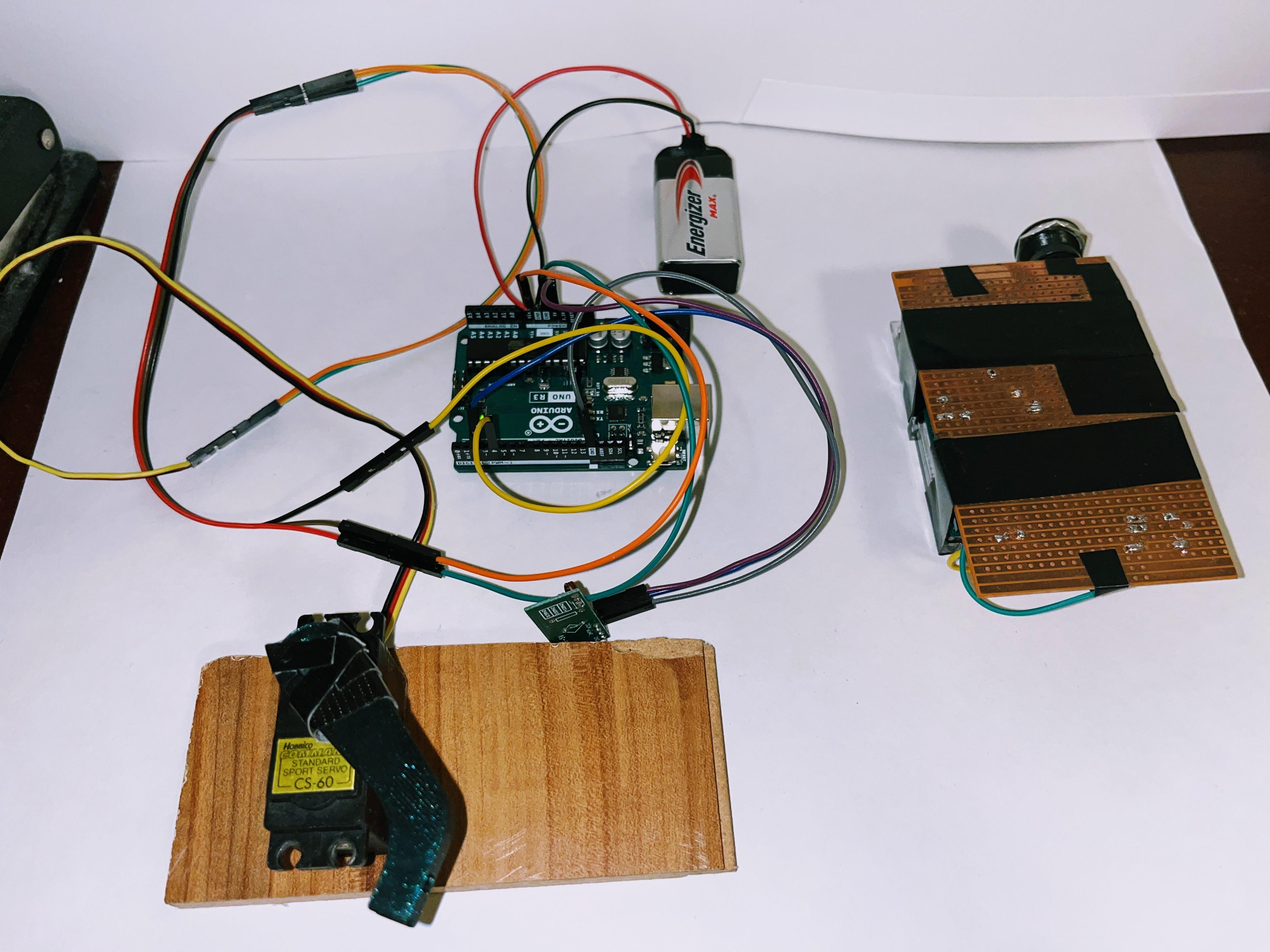
In this tutorial, I will show you how to use an Arduino microcontroller to create a garage door button presser remote. I created this project for Ms. Berbawy's 2022-23 Principles of Engineering class as my SIDE project. In essence, it is an RF-controlled button presser that can press a button such as a wall-mounted garage door opener or light switch. Using a 2-piece 315MHz transmitter and receiver combo, we will create a basic RF communication device. When completed, the user may send a remote signal from the transmitter to the receiver, which will then turn a servo motor with a 3D printed "finger" attached which will press a wall-mounted garage door opener. This project is meant to demonstrate how RF remotes work; an actual remote from the manufacturer will certainly be better. Nonetheless, this is a fun project that could possibly put to real life application. Please verify that it is legal to operate 315/433MHz without a license in your country before proceeding.
Supplies
Material List:
[2] Arduino Uno (My Arduino unit of choice for this build)
315MHz receiver and transmitter
USB A-B Cable (Connects Arduino to PC)
Breadboard for prototyping
Servo (CS-60), but any similar sized servo will work
Servo horn
9V Batteries, Push Button, Switch
Tool List:
CAD Software, Slicing Software
3D Printer (Prusa MINI)
Soldering Gear
Garage door opener (wall mounted)
RC Switch Library for Arduino IDE
Connect Receiver and Transmitter
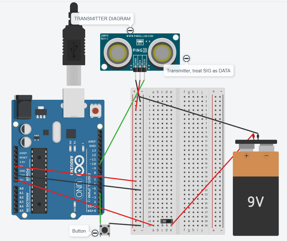
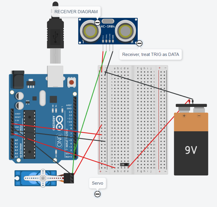
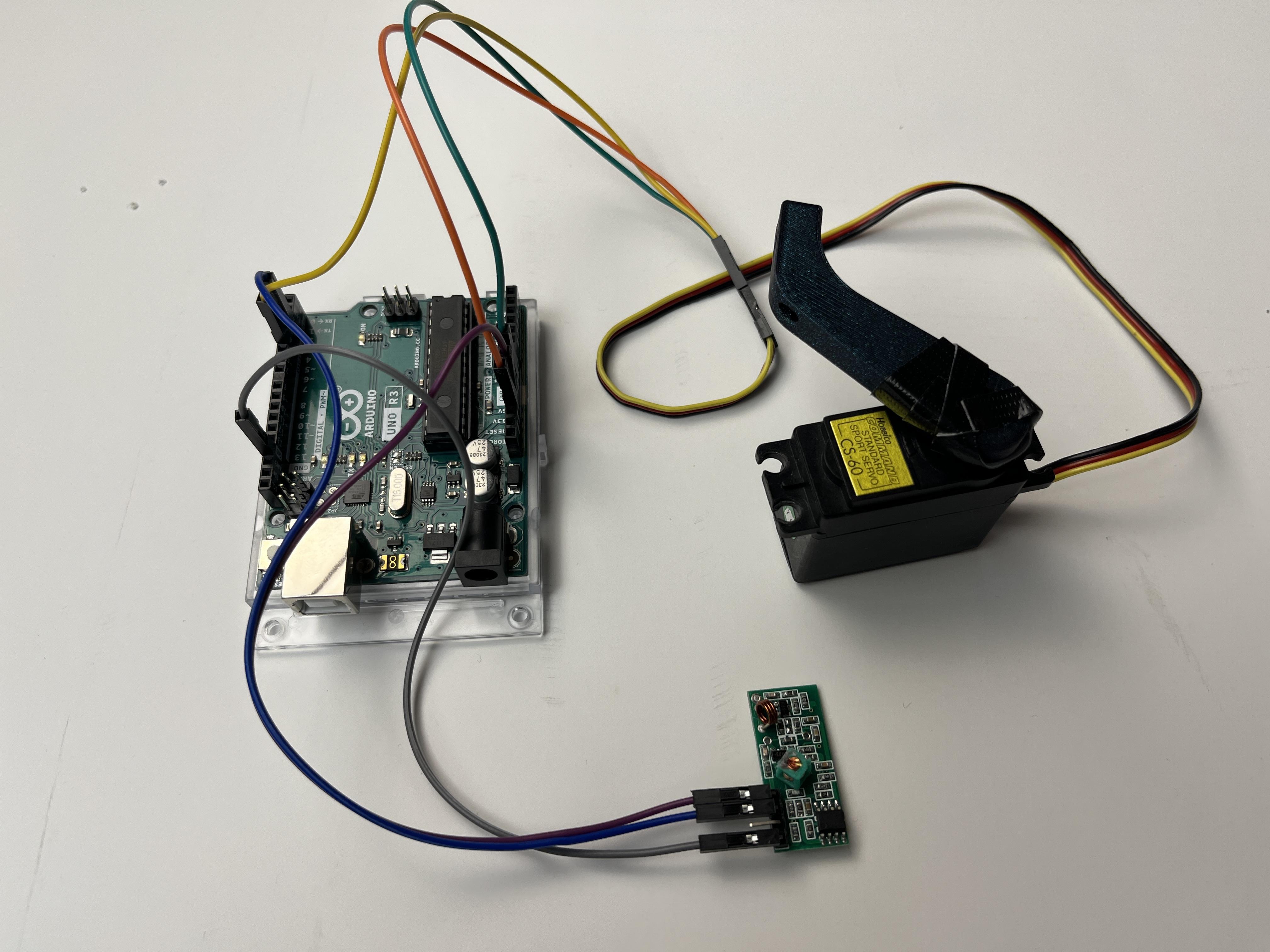
Using the breadboard, Arduinos, jumper wires, and transmitter/receiver, we will create a preliminary build for the project for prototyping. It is split into two parts—the transmitter and the receiver/motor arm. I have attached diagrams of what it should roughly look like.
First is the transmitter: we attach a 9V battery to the VIN port with a switch in series and connect the Arduino to the transmitter and button, putting each wire in its correct place. The transmitter will typically have 3 pins: VCC, DATA, and GND (ground). VCC is your power input—it needs to be connected to the 5V pin on the Arduino somehow. GND is ground and should be connected to its respective GND pin as well—this makes the circuit complete and lets current flow through the transmitter. I put my transmitter DATA pin into port 10 and button into port 4, I advise you to do the same since not all the numbered pins do the same thing (digital/pwm).
The receiver and servo are similar, except the servo goes into port 4 and receiver into port 2. The receiver I have has 4 pins, VCC, DATA, GND, and an unlabeled 4th, which we will simply ignore.
We will need a servo horn to attach to our servo head—a servo horn is an adapter piece that lets the servo apply torque on more conventional objects like arms and wheels. Looking at the head of a servo, you can see that it is round like a drill, meaning it can only perform turning actions. To I cut off half of my servo horn since I could only find dual tipped horns in my materials at hand, feel free to use any servo horn that can fulfill your needs. Just be sure that the servo horns you use match the head of your servo.
Write Code for Arduino, Upload and Test
Download the Arduino IDE for your respective OS
Download the RC Switch library either from GitHub or install it directly in the IDE
Sketch>Include Library>Manage Libraries>Type in RC Switch, install
RC switch is an Arduino library by sui77 that allows an Arduino to control commercial 315/433MHz transmitters and receivers and send and receive signals through them. This project is powered by RC Switch, since it allowed my transmitter and receiver to communicate with each other. We are only trying to make the transmitter and receiver communicate with each other, so the code is not too complicated. Arduino code is written in the C++ language.
Create 2 separate sketches, one for the transmitter and one for the receiver. Connecting your transmitter Arduino to your computer first using the USB A-B cable, write the code that will allow your receiver to transmit some signal upon pressing the button. Do the same for the receiver, writing code that allows you to check that it has received the signal, and then telling the servo to move.
I have attached my .ino file for both: receiveswtch.ino for the receiver, and remoteswtch for the transmitter.
Line by Line Breakdown (Receiver)
#include <RCSwitch.h>
#include <Servo.h>

Servo myservo;

RCSwitch mySwitch = RCSwitch();


*/ Our first lines of code include the RC Switch and Servo Libraries, we then create the Servo and RC switch objects respectfully. /*


void setup() {
  Serial.begin(9600);
  myservo.attach(4); // servo attached to pin 4
  myservo.write(0); // reset servo to 0 position
  mySwitch.enableReceive(0);  // Receiver on interrupt 0 => that is pin #2
}


*/In the setup portion of the C++ code, we establish serial communication at a 9600 baud rate, all standard practice. Then we attach the servo to pin 4, and reset the arm to 0 degrees, although you can alter this to your specific starting position. We then connect the switch to interrupt pin 0, pin #2 on the physical board./*


void loop() {
  while(mySwitch.available()) { // check if the receiver has received a signal
    int value = mySwitch.getReceivedValue(); // get the value of the received signal

    if(value != 0) { // check if the received value is valid


*/Starting the loop function, we check if the receiver has received a signal with a while function, and set the binary value of the received value to an integer. Next, we check if the value received is valid, although you can change this function to equal the specific binary code you choose to transmit, ie /*


//if(value = 01101000 01101001) {} //this translates to HI in english

      myservo.write(0);// servo moves to buttonpress, then nearly immediately moves back to start position
      delay(200);
      myservo.write(90); // Play around with the angle of these 2 and the delay, a longer delay between means servo holds it longer
      delay(5000);

      Serial.println(value); // print the received value to the serial monitor, not necessary in final stages
    }
    mySwitch.resetAvailable(); // reset the receiver to listen for the next signal
  }
Immediately within that if function, we command the servo to move the arm to press and move back in 1 continuous motion—a button press. I set a delay of 5 seconds to avoid overloading the Arduino with requests.
Line by Line Breakdown (Transmitter)
#define BUTTON_PIN 4 // Variable of button as pin 4
#include <RCSwitch.h>
RCSwitch mySwitch = RCSwitch();

*/ Including the RC switch library again, and defining pin 4 as the pin we will use for our button. Note that I don't include the servo library since this is on a different Arduino, the transmitter./*


void setup()
{
  Serial.begin(9600);
  pinMode(BUTTON_PIN, INPUT_PULLUP); // Button pin 4 set as input in pullup, makes it work faster than INPUT alone
  pinMode(LED_BUILTIN, OUTPUT); // Builtin LED connected as output
  // Transmitter is connected to Arduino Pin #10
  mySwitch.enableTransmit(10);
  // Optional set number of transmission repetitions.
  //mySwitch.setRepeatTransmit(3);
}


*/ Our setup function establishes serial communication and our button pin (4) as input in pullup mode, so the HIGH state is the default for your switch. I find that this makes the button more responsive for some reason. We then establish the built-in LED as output, this is just to make it flash when you press the button as a visual indication of it working. The transmitter is connected to pin 10. /*


void loop()
{
  Serial.println(digitalRead(BUTTON_PIN));
  delay(100);
  if (digitalRead(BUTTON_PIN) == LOW){ // If the button is pressed...

    mySwitch.send("01101000 01101001"); // Send 2 signals in 315mHz, this says HI
    delay(1000);
    mySwitch.send("01101000 01101001");


*/ In the loop function, we call a read of the button's state every 100ms. When pressed, it reads a LOW state due to pullup mode inverting the effect (usually pressing a button will connect the circuit, changing the voltage state from LOW [0] to HIGH [max], but since we used pullup it uses an onboard resistor to invert the effect). Upon gauging that the button has been pressed, the transmitter sends 2 signals, with a 1-second delay. You can change the code sent by editing the binary to make it an exclusive passcode, just make sure it matches up with your receiver sketch. /*


  digitalWrite(LED_BUILTIN, HIGH); // This block of code is just flashing the on
    delay(200);                      // board LED for a visual display that the controller works
    digitalWrite(LED_BUILTIN, LOW);
    delay(200);
    digitalWrite(LED_BUILTIN, HIGH);
    delay(200);
    digitalWrite(LED_BUILTIN, LOW);

    delay(5000); // 5 second delay
  }
This part is self-explanatory, just flashing the on-board LED upon button press to confirm that the remote works, followed by a delay.
Designing Arduino Enclosure for the Transmitter Using CAD
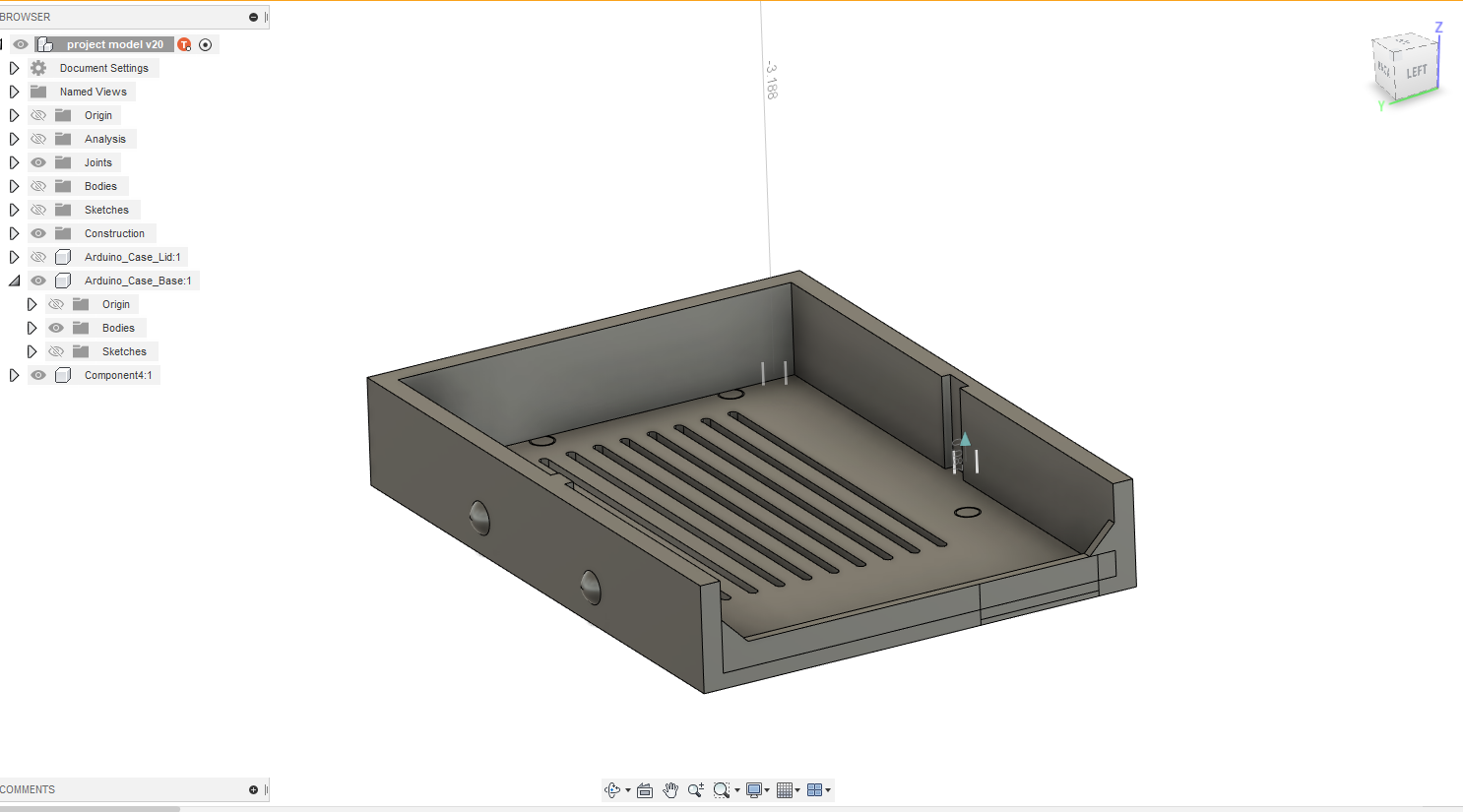
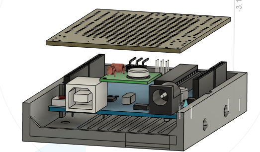
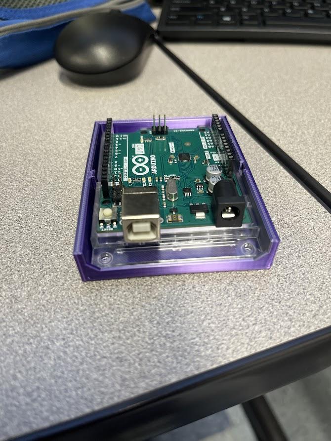
Using your CAD software of choice, design and print a functional enclosure for your remote that protects the sensitive components and allows for convenient repair and operation. I used Autodesk Fusion 360 for my build, but any modern CAD software should suffice, as long as it is compatible with your 3D printer and slicing software.
We will create a model of your case by taking measurements of the Arduino and accommodating for any additional features you want, such as a battery compartment. Moving away from out previous prototype of breadboarding, our aim is to convert the prototype remote into a compact, handheld, standalone device. I recommend importing existing CAD models of the components of your project into Fusion so that you can get a rough idea of what your case should look like. As shown in the second picture, I imported models of an Arduino, stripboard, and transmitter from the internet so that I could visualize the transmitter in a finished state.
You will need a case for the transmitter portion, and optional enclosure for the receiver. I have attached some pictures of the enclosures I made for my build, but I will not give CAD files because it varies from project to project depending on your needs and how you want to configure it.
Finish this step and step 4 before proceeding to 5 and 3D printing anything.
Designing Servo Arm Using CAD
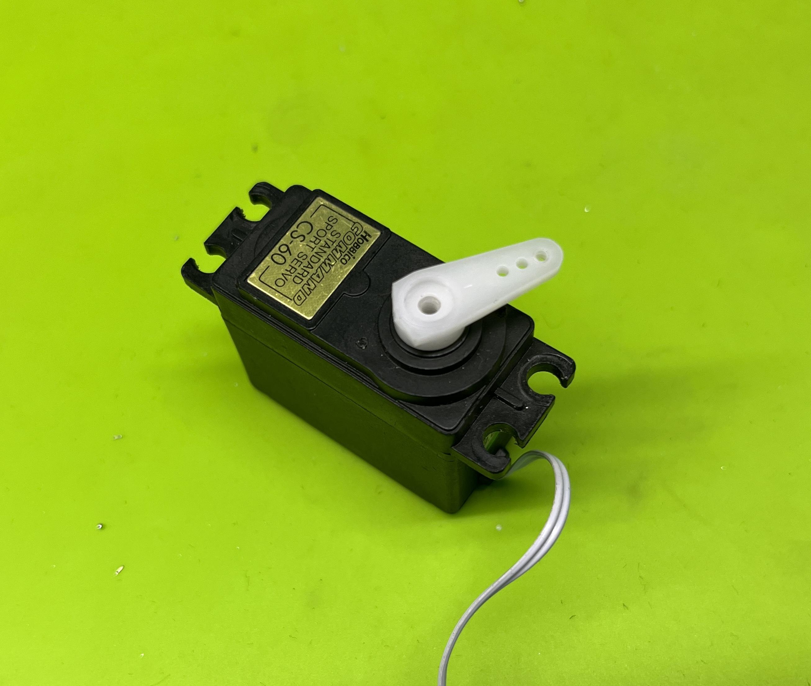
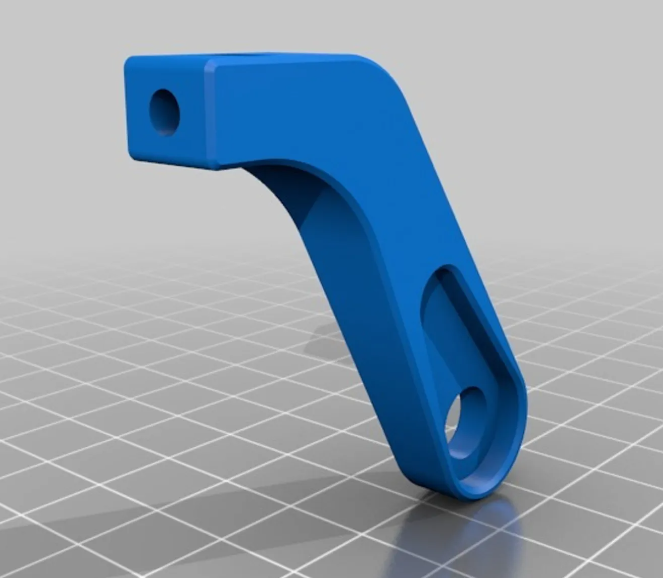
A servo motor is a motor that allows for precise control of angular position, velocity, and acceleration, so that is what we will use to press the garage door button. Although a linear actuator servo would better fit the needs of this project, I did not have one on hand, so this tutorial is specifically for rotational servos. My servo of choice was a CS-60 Hobbico standard sized servo, but any similar sized servo will work.
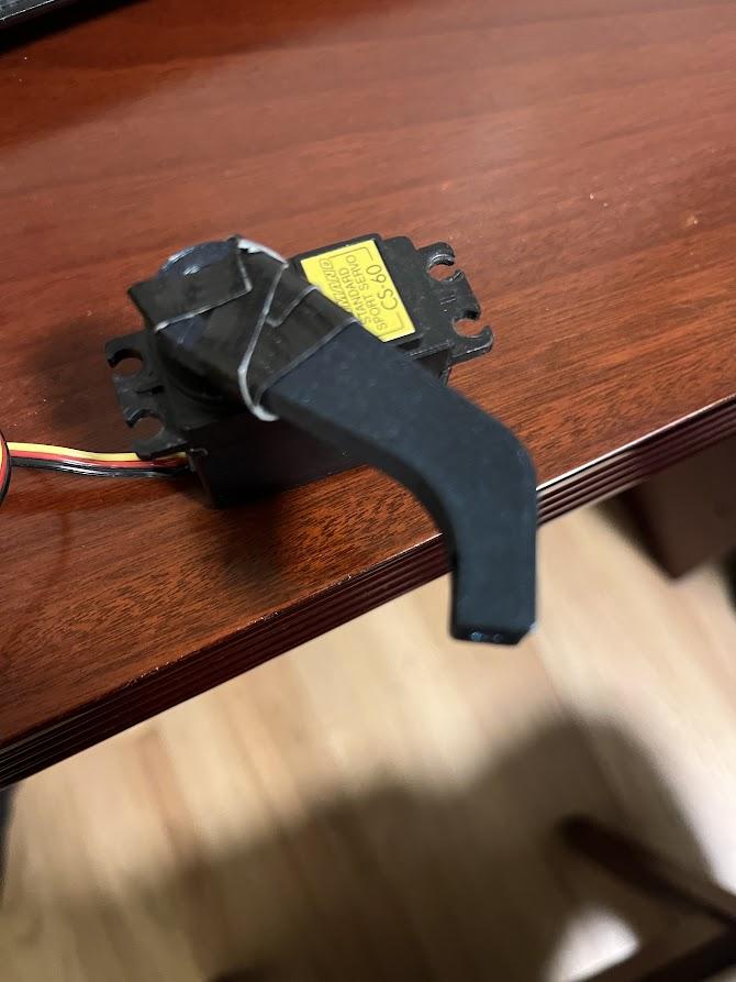
You will specifically need an arm for your servo since it is unable to press the button on its own. Taking advantage of a servo's to rotate to any angle in a 180 degree range of motion, we will create an arm that can create enough leverage to press a button of moderate stiffness. I researched existing models of servo arms on the internet for reference and then created my own, but I have attached images of mine for reference to save you some trouble. Taking the same steps as the case, take measurements of your servo horn, and then create an arm with some degree of bend and a hole to fit the servo horn.
The pictures of the servo arm show the horn hole, and I superglued/duct tape my arm onto the horn to ensure there is absolutely no movement. This was just a preventative measure because I was concerned that it wasn't a perfect fit and might wiggle or fall off.
Export the CAD Files, Slice and Print, Repeat for Testing
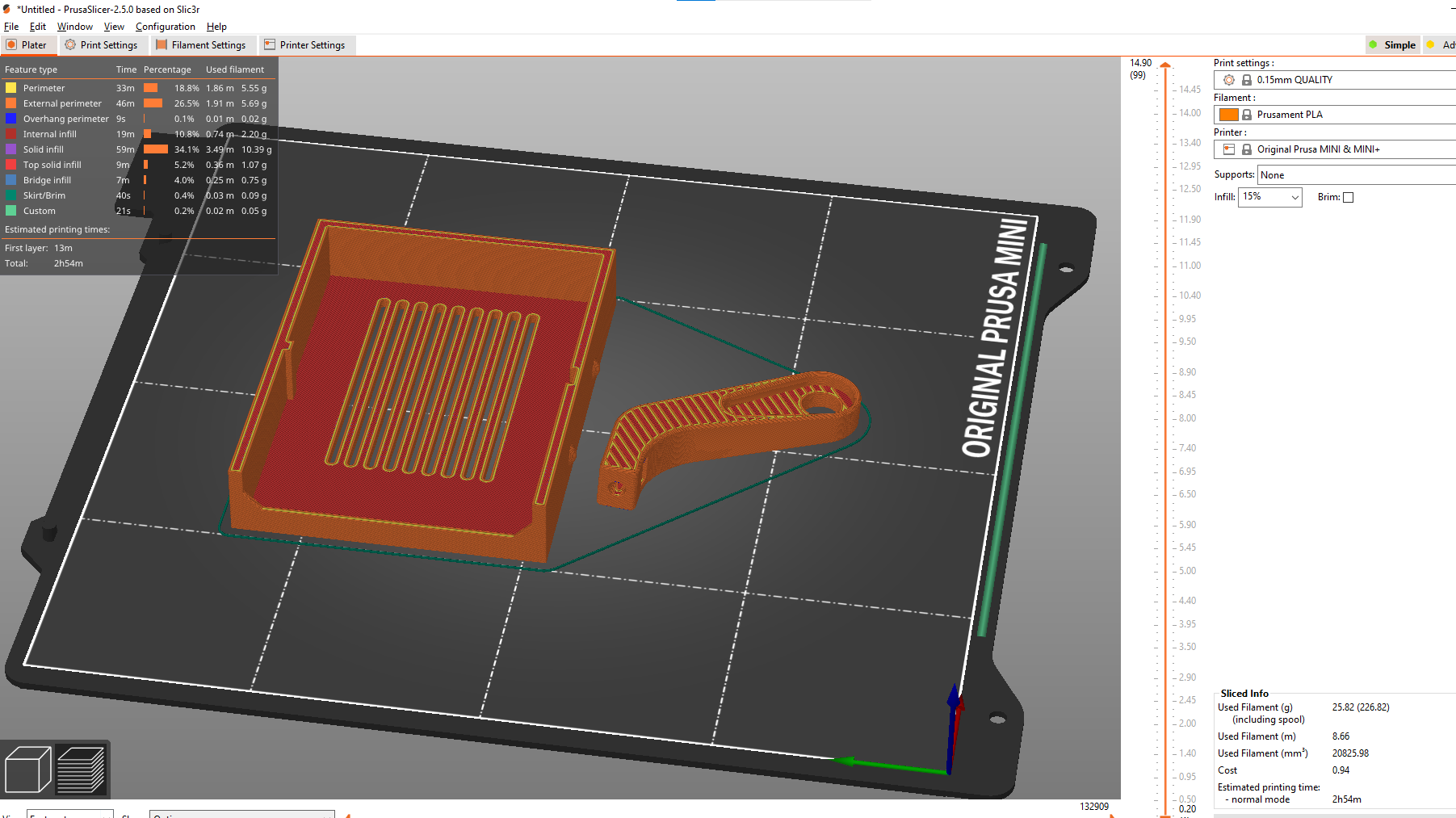
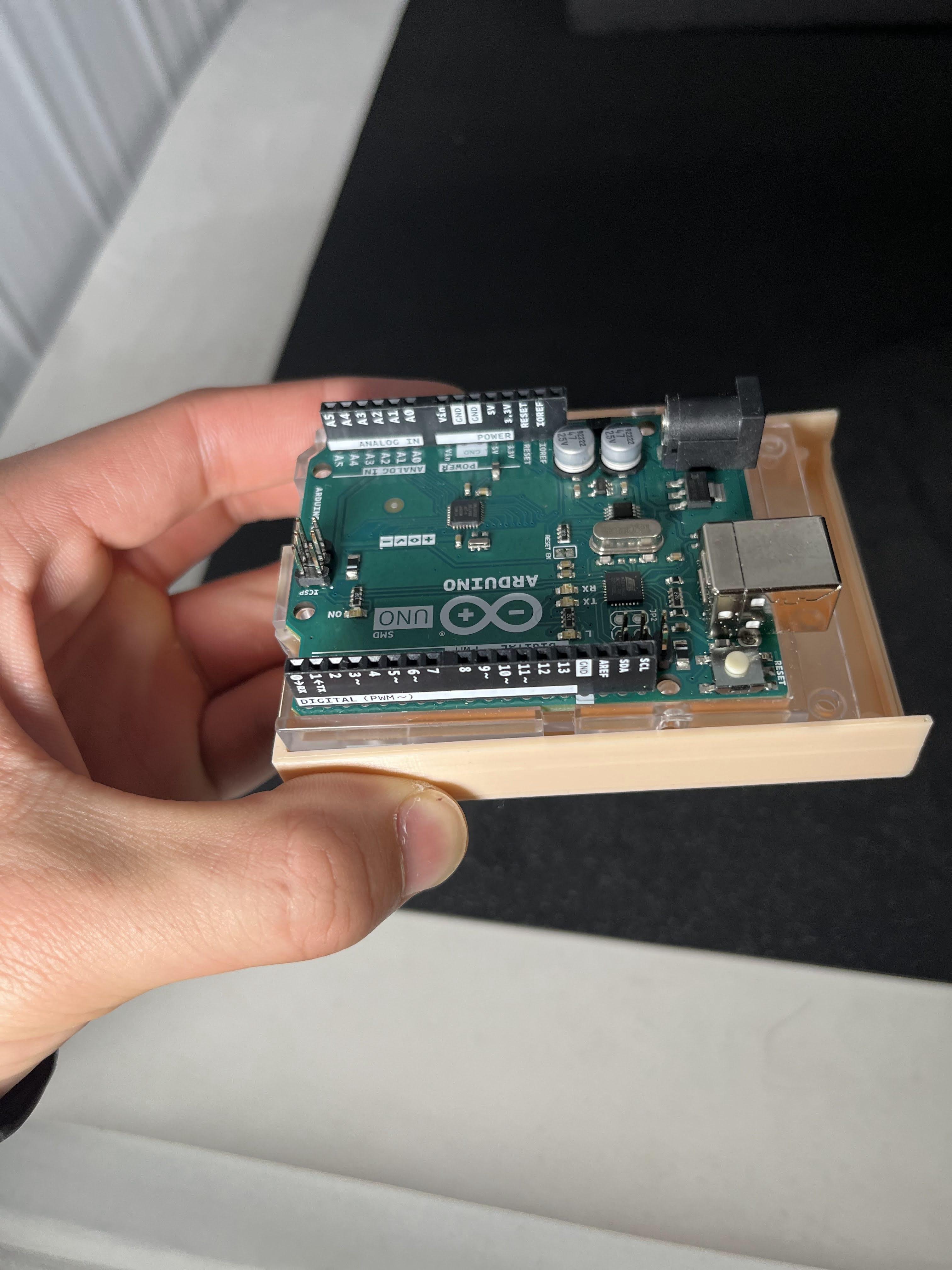
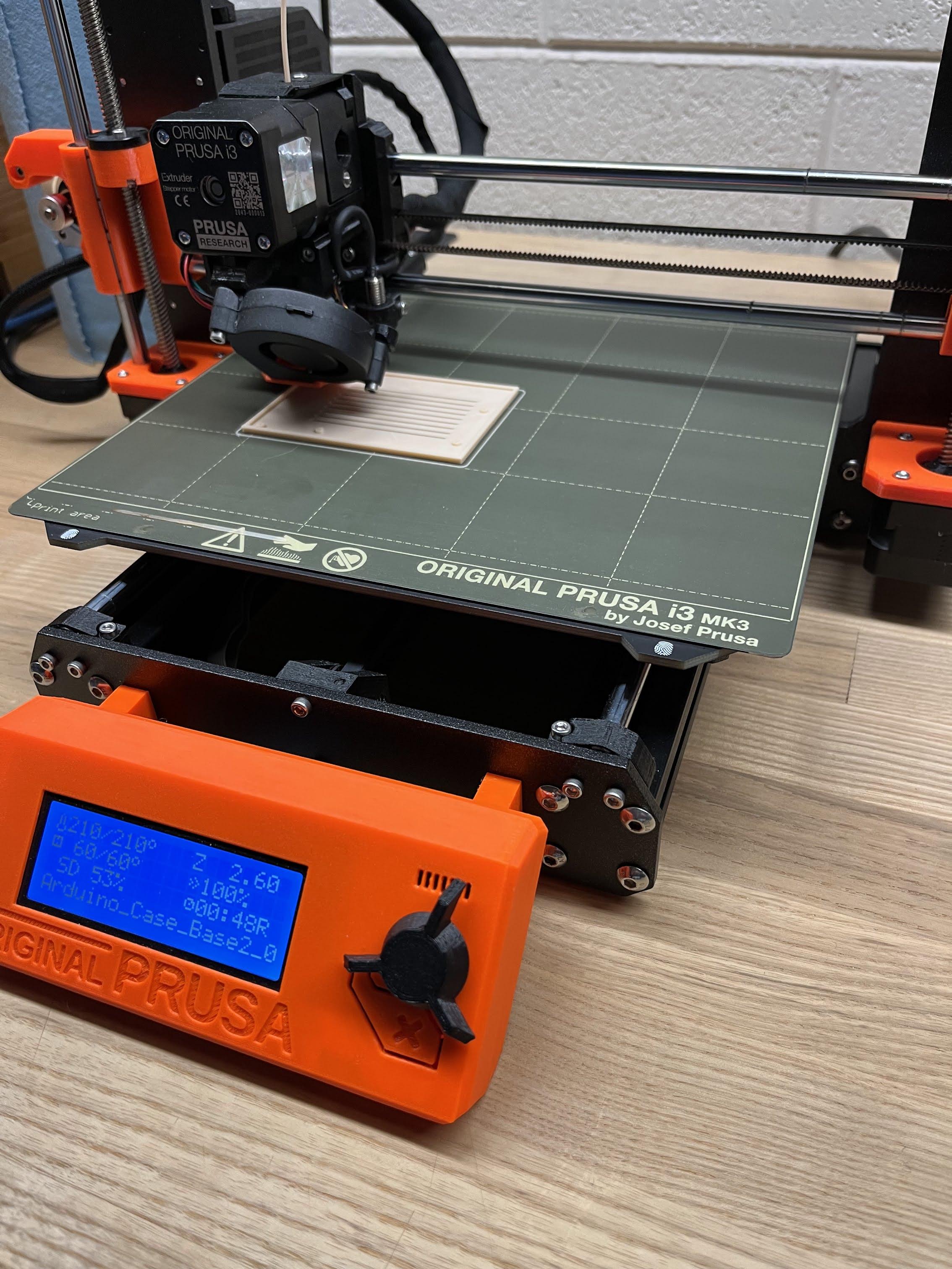
Export your STL files from the CAD software and import them to PrusaSlicer. Check that there are no floating bits that may jeopardize the print, and print the G-code on the 3d printer. This phase is a lot of trial and error—it will take many attempts before you achieve a print that is fully satisfactory for your needs. This means that you should create test prints and expect to reprint many times before settling on a final build.
Soldering the Wires to a Stripboard, Optional Steps
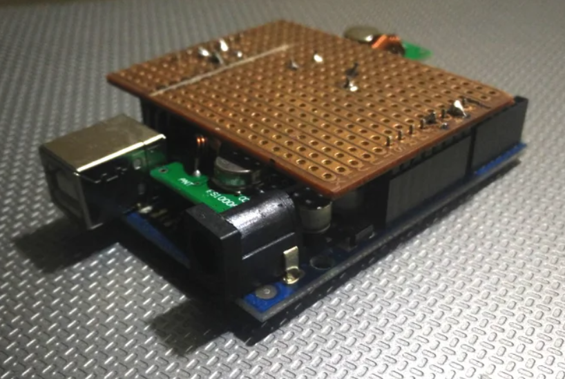
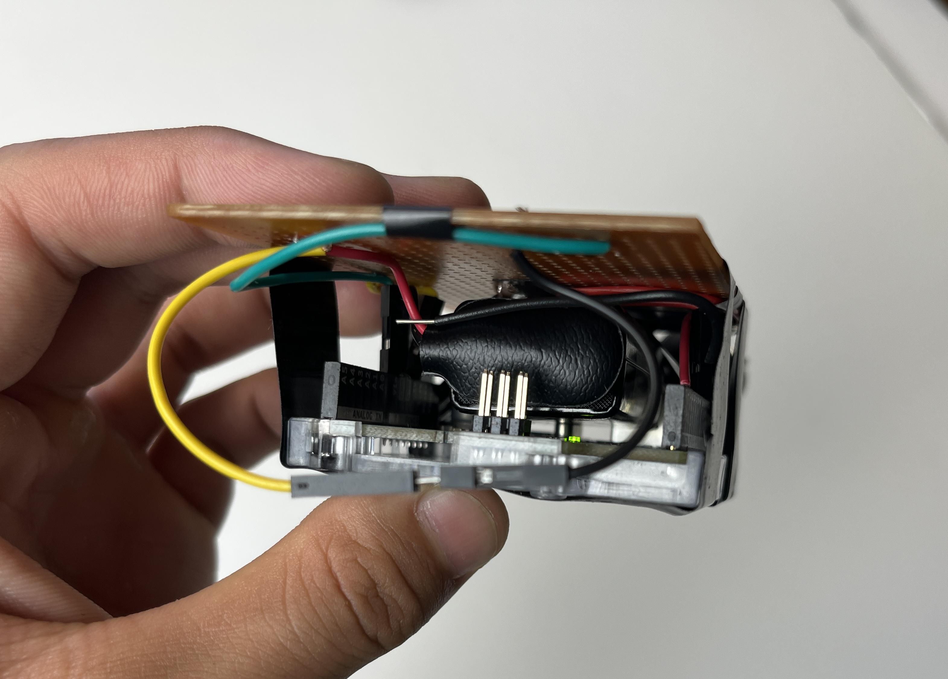
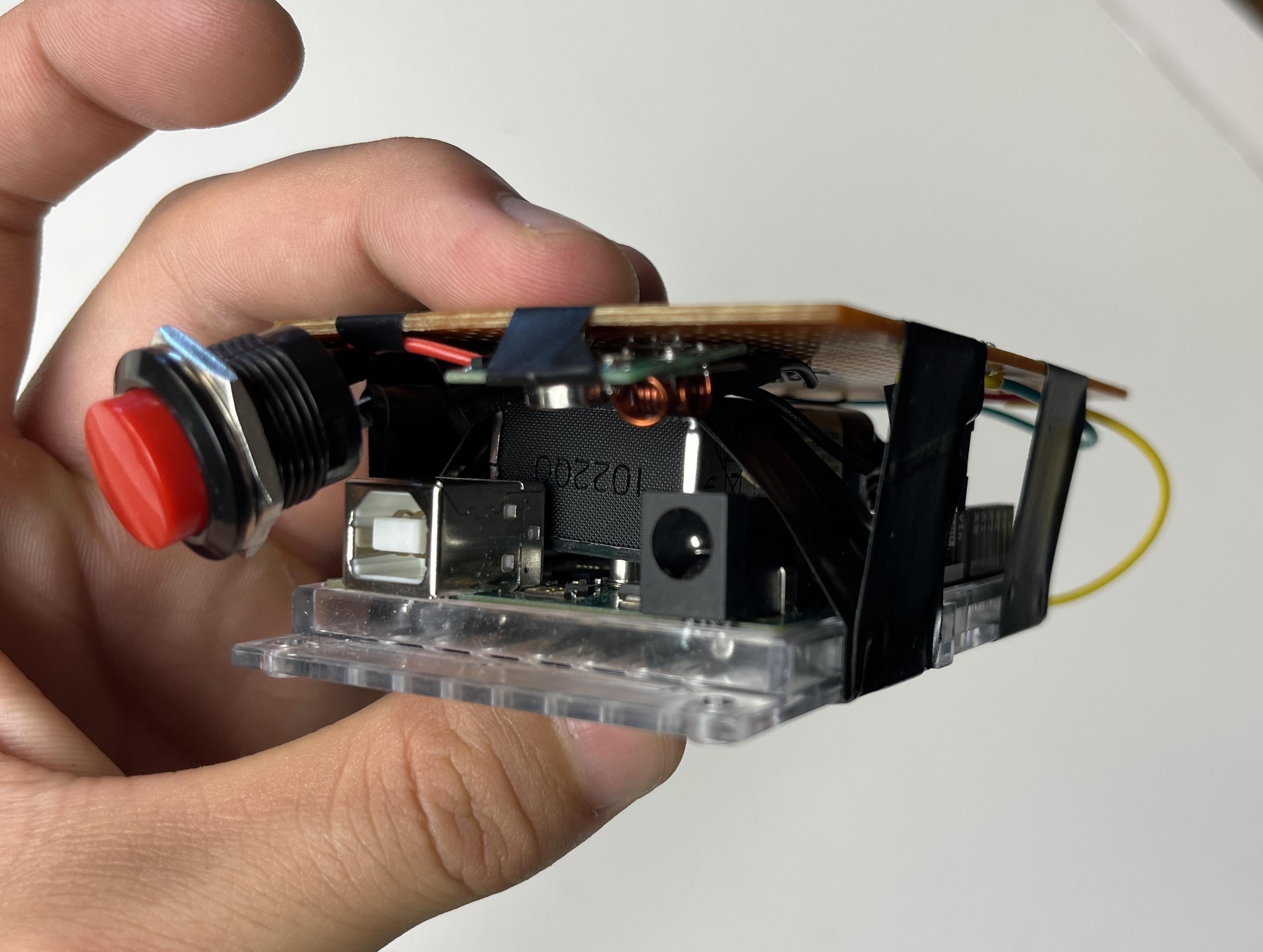
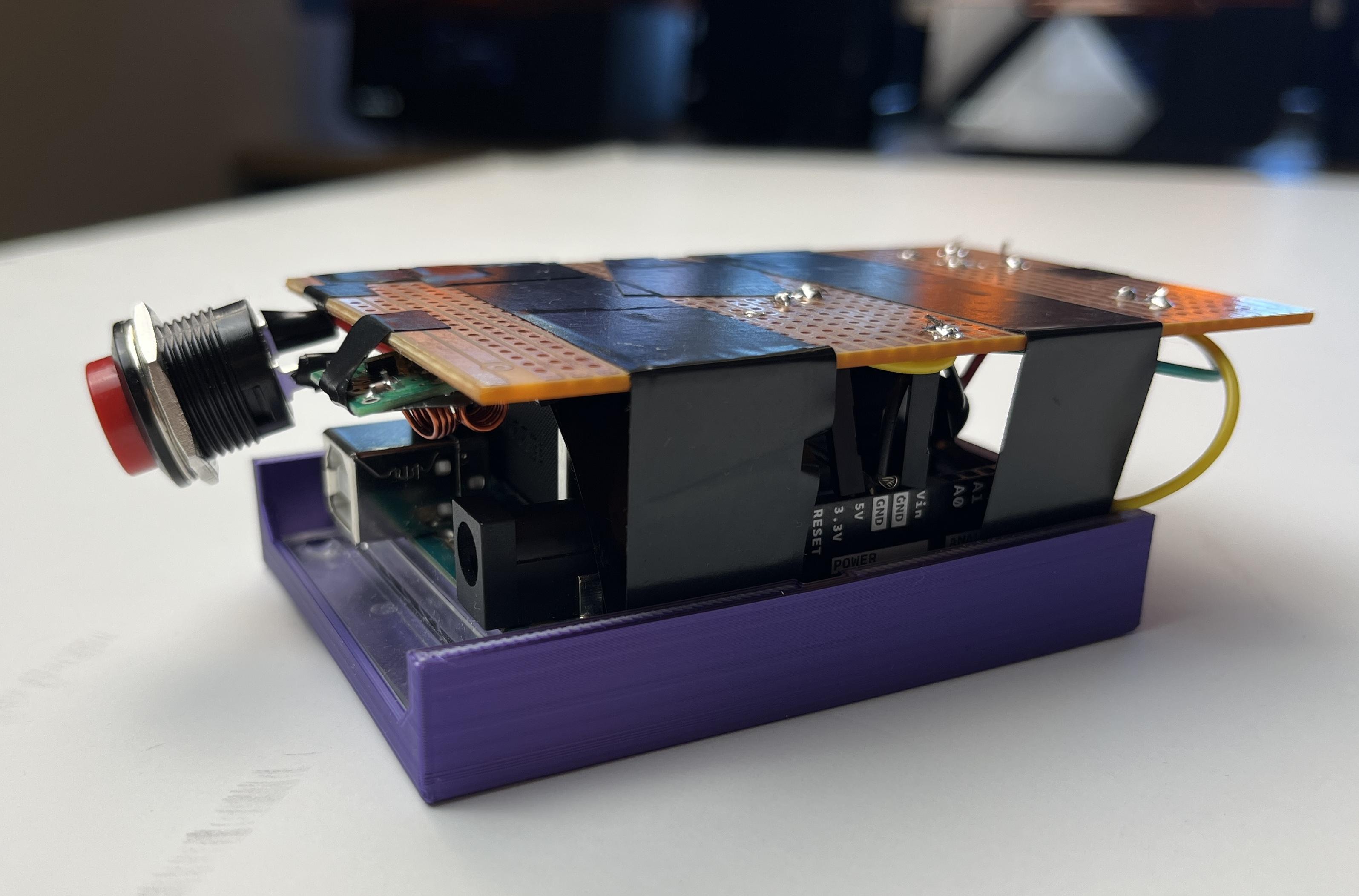
Tidy up the loose wires by cutting them short and attaching them to your stripboards with solder. Using the rows of connected copper conducting strips, insert the cut exposed wire end from the resin side (no copper) and solder on the opposing side (with copper). Referencing the first photo, you can see that we leave the copper side of the stripboard facing up away from the Arduino board, since solder is supposed to be attached on this side. Naturally, the wires then go on the resin side—our desired result. Using the stripboard is very similar to breadboarding since all of the slots in a single column are conducting and connected. With that in mind, we just move the wires from the prototype onto the stripboard and solder them on. Solder the wires to the board by cutting off the end and exposing the metal with a wire stripper, inserting the end into the desired slot on the resin side, and then soldering it on the copper side. Everything that needs to be soldered should be done first, then connect the jumper wire ends to the board all at once. This just streamlines the process.
The final configuration of your project should be what ever you decide is most conventional and easy to use, but for me, I placed the receiver and button sandwiched between the stripboard and Arduino. Reference the third picture. I solved the issue of battery placement by using electrical tape to secure it directly on top of the board—if you decide to do this, be sure to not cover pinholes you will use with tape. You can see the battery connector in the 2nd photo, in the 3rd the tail end of the battery. Another possible option is including a battery holder in your 3D printed case, but you may not like the weight distribution. The switch I included between the stripboard and Arduino.
I say that a case is optional for the receiver since you can lengthen the wire to the servo and just place the receiving Arduino in a small box safe in a corner. Furthermore, you want to keep the receiver exposed so it can receive signals from your transmitter. Keep it away from metal surfaces, since they can deflect and absorb the radio waves.
Mount your servo next to the button you wish to press, and play around with the angles of the servo until you find the optimal button press length and depth. You can mount your servo the wall with a CAD mounting clamp screwed into the wall. I chose to mount a small wooden board to the wall and fasten the servo to that, which you can see in the video.
Linked below is a video demonstration used on my light switch