Building and Using a MOSFET Shield for Arduino
by MakersBox in Circuits > Arduino
21670 Views, 101 Favorites, 0 Comments
Building and Using a MOSFET Shield for Arduino


At some point in Arduino, you are going to want to leave the calm waters of blinking an LED and control something a little more powerful. To do that, you are going to need a little help.
Transistors can be used as a switch using the Arduino's digital signal for control. A MOSFET is an ideal type of transistor for this application, and can handle several amps of current and up to 30 volts!
I've designed an Open Source Arduino shield to utilize three MOSFETs, which can be used to control motors, solenoids, or even the three channels of an RGB LED string!
Gather the Parts, Tools, and Supplies


You can build this circuit with a number of various parts, but these are the ones I've found to work:
PCB:
Digikey parts:
- 3 - MOSFET IRLB8721, IRLB8721PBF-ND
- 4 - TERMINAL BLOCK 3.5MM 2POS, ED1514-ND
- 1 - LM7809 Voltage regulator, LM7809ACT-ND
- 1 - 100 uf 35V Cap, 93-1081-ND
- 1 - 10 uf Cap, P997-ND
- 1 - 1 uf Cap 50V, 478-7667-ND
- 3 - Diode 1N4001, 641-1310-1-ND
- 3 - 10K resistor, 1/8W, CF18JT10K0CT-ND
- 1 - 1K resistor, 1/8W
- 3 - 330 resistor, 1/8W, CF18JT330RCT-ND
- 1 - 3mm LED, red, 160-1955-ND
- 3 - 3mm LED, green, 160-1710-ND
- 1 - power shunt, 2-881545-2-ND
- 1 - CONN HEADER .100" SNGL STR 40POS, S1012EC-40-ND
Optional:
- 2 - CONN TERM BLOCK 2.54MM 2POS PCB, ED10561-ND
- 1 - CONN TERM BLOCK 2.54MM 3POS PCB, ED10562-ND
-
Heat syncs, HS198-ND (with analog headers installed, will only fit on one of the MOSFETs).
Tools and Supplies:
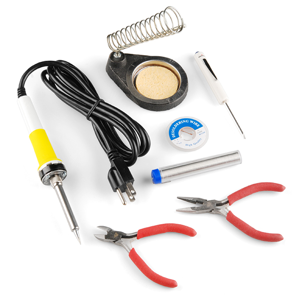
For my workshops, I use SparkFun's Beginner's ToolKit which has most of what you need:
- Soldering iron.
- Solder
- Wire nippers
- Desoldering braid (hopefully not needed, but you never know).
A kit for this project is available on Tindie.com. Purchasing the kit will save you the time and expense of ordering from several different vendors and avoid the minimum PCB order premium. You will also be helping me develop and share other projects!
Ladies and Gentlement, Start Your Irons


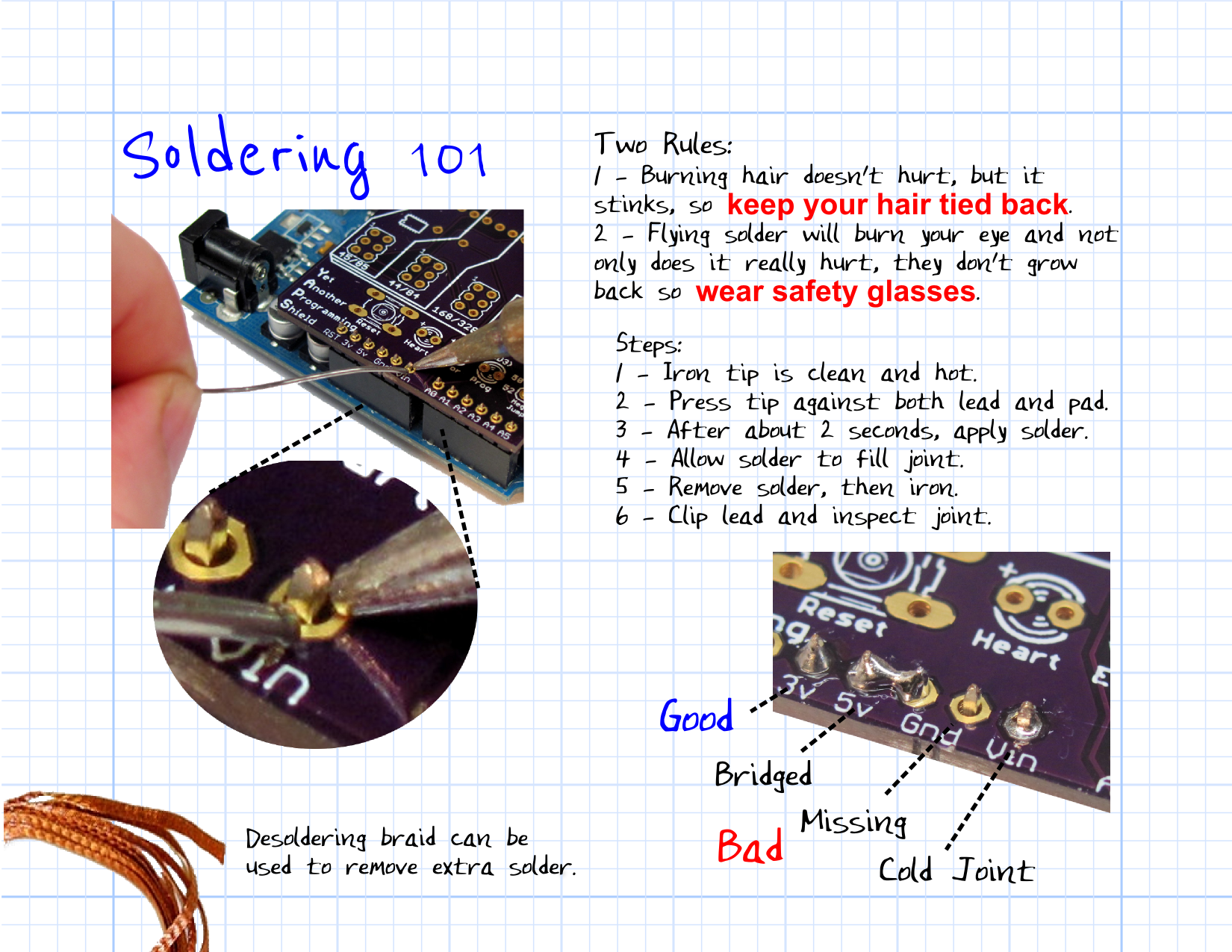
We are going to assume you have some kit-building experience. If you need some help soldering, head over to www.sparkfun.com/tutorials/213 to brush up.
The order of assembly is largely a matter of preference. If you don't have a helper or a vice, I generally go from lowest height to tallest so when the board is reversed on the table, the parts stay in place.
Resistors: Let's start with resistors since they are the most plentiful, lowest seating, and easiest to solder. They are more heat resistant and will give you a chance to brush up on your technique. They also have no polarity, so you can put them in either way.
Diodes: Now you are warmed up, time to try something with polarity. Add the diode observing the white line on the PCB and the black band on the diode. This is the "kick-back" diode and the circuit will not work if it is in backwards.
LEDs, Capacitors


LEDs:
Light emitting diodes have a polarity. Place the longer leg in the hole with the silkscreen "+" next to it. The red LED indicates the shield is powered (not just from USB), and the green LEDs indicate the MOSFET outputs are engergized.
Capacitor:
The 1uF ceramic capacitor does not have a polarity and can go in either way. The 10uF and 100uF electrolytic capacitors do have polarity. Like the LEDs, place the longer lead in the hole with the silkscreen "+" next to it. Capacitors are mainly to keep the power signal to the microcontroller steady while the loads are switching on and off.
Terminals

The two-position terminals allow us an easy way to connect power and loads to the board. They are optional if you are building a permanent installation and want to just solder the wires directly. This also applies to the optional input terminals.
The output terminals have a 3.5 mm spacing while the input terminals, which handle less current, have the 2.5 mm (0.1") spacing.
MOSFET, Voltage Regulator, and Power Jumper


The work horse of the circuit is the metal–oxide–semiconductor field-effect transistors (MOSFET). They act as a switch for the high-current source, using the Arduino's digital signal as the control. You can learn more about how they work at http://en.wikipedia.org/wiki/MOSFET.
You need to carefully identify the difference between the LM7809 voltage regulator and the three IRLB8721 MOSFETs since they come in the same TO-220 package and look fairly similar except for the markings (see photograph).
We also need to allow the choice of input power between the shield's terminal and the Arduino's barrel jack. Clip a 3-pin segment off the pin header and solder it in place adjacent to the 10uF and 100uF capacitors.
Shield Headers


I like to use an available Arduino as a jig to hold the pins in place. Cut two 6-pin segments and two 8-pin segments from the pin header. Place them in the Arduino with the short end pointing upward. Place the shield in place and solder the pins.
Inspect and Test


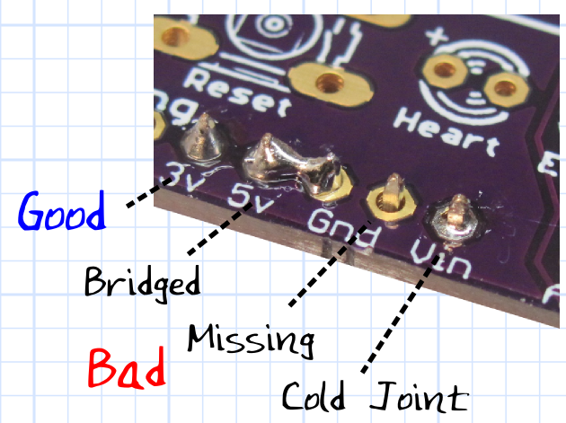
Take a few moments to carefully inspect your solder joints. Use a magnifying glass if you have one. You are looking for missing or bridged joints.
If you are a neat freak or will be showing off your handy-work to your friends, you can remove the solder flux residue using Goo Gone or flux remover.
Use


Power Source:
- You can connect up to 30V DC to the terminal. This will power the Arduino with 9V through Vin.
- With the power selector to "TERM", the input voltage is supplied to the MOSFETs.
- With the power selector to "JACK", the regulated 9V output is also supplied to the MOSFETS (1A limit).
- You can provide up to 12V DC to the Arduino via the Arduino's 2.1mm barrel jack. With the power selector to "JACK", the 12V is supplied to the MOSFETs via Vin.
The red LED will light when the circuit is powered in either manner.
Code:
MOSFETs are connected to Arduno digital PWM pins 3, 5, and 6. These must be set to output:
pinMode(3, OUTPUT);
You can then control the output of the MOSFET using either:
digitalWrite(3, HIGH); // fully on

analogWrite(3, 124);   // PWM values from  0 - 255
Happy MOSFETting . . .
If you build and use it, let me know what for and how it went!
- Ken
Downloads
Options

I've laid the board out so you can use heat shields for the voltage regulator and two of the MOSFETs if you are drawing enough load to heat them up. The traces on the PCB are 80 mils wide, so total current would be limited by those to several amps.
It is likely that the loads you want to control would be triggered by some sort of input.
- Light controlled by a photo resistor
- Fan speed controlled by a potentiometer.
- Solenoid controlled by a pressure dector.
- I've laid out three analog inputs on the side of the board with 0.1" spacing so you can add headers, terminals, or just solder leads in place.
I've also laid out two of the analog inputs and a ground such that you can attach a temperature sensor like the TMP36 or potentiometer in a power-signal-ground arrangement. Simply set pin A4 pinMode to OUTPUT and digitalWrite it HIGH to supply 5 volts. Use pin A5 to read the signal and the GND for ground.