Building and Motorising a 300mm F/5 Dobson Telescope With Equatorial Table for Astrophotography
by d_legourrierec in Workshop > Science
1520 Views, 17 Favorites, 0 Comments
Building and Motorising a 300mm F/5 Dobson Telescope With Equatorial Table for Astrophotography

This documentation describes the making of a Dobson telescope starting with a blank disk of glass all the way to taking photos of galaxies and nebulae. As a member of an astronomy association (SAR: Société d'Astronomie de Rennes, Brittany), I could benefit from the know-how and advice of my fellow astronomy amateurs, many of whom turned out to be very knowledgeable in many fields (DIY, electronics, mechanics...).
Obviously, this is a very long project (never ending I could say: there will always be something to improve). The reader of this Instructable will be taken through all the steps, many of which are not meant to be exactly reproduced but are rather presented here as a source of inspiration and ideas.
CREDITS
A big thank you to the following people for their contribution at various stage of the project:
- Michel L and all members of the mirror workshop at the astronomy association for the guidance in the process
- Didier S and all members of the astrophoto group at the astronomy association for advice and discussions
- Jérôme (brother in law) for the 3D focuser
- Xavier for the help moulding the plaster polishing tool
- Frank Grière (mirro-sphere) for the high quality of the parabolisation of the primary mirror
- mum for the sewing lesson (lycra skirt of the telescope)
- Vincent Berenz for the camera-zwo-asi Python code and the rapid response and update to the repository
DIY is like travelling:
it's not so only the destination that matters,
it's also everything you learn in the journey
STEPS and TIMELINE
- feasibility study
- mirror: grinding - febr. 2014
- mirror: smoothing
- mirror: polishing
- mirror: figuring (parabolisation)
- structure: primary box - febr. 2018
- structure: secondary box
- structure: serrurier truss
- structure: rocker
- structure: balancing
- structure: azimut disk
- structure: focuser
- structure: finishing touches
- structure: transporting
- first light: selection of eyepieces - July. 2018
- first light: collimation
- first light: visual observations
- equatorial table: construction - 2019
- motorisation: equatorial table - 2020-21
- electronics: equatorial table
- motorisation: rocker alt axis 2022 / 2023
- motorisation: rocker azimut axis
- motorisation: secondary box: focuser
- electronics: rocker alt alz, focuser, sensors
- controls: infra-red remote - 2022
- controls: python interface
- astrophotography: HD cam behind eyepiece
- astrophotography: deep-sky camera
- astrophotography: images
- roadmap
- power consumption
Supplies
- mirror grinding
- blank disk of glass 300mm diameter*: mirro-sphere.com
- abrasives: astronomy association
- ceramic tiles: local DIY shop
- epoxy glue: local DIY shop
- plywood: surplus from local companies and DIY shops
- electronics: aliexpress
- mirror polishing and parabolisation
- cerium powder: astronomy association
- pitch: astronomy association
- staturoc plaster: art and craft online reseller Rougier & Plé
- telescope structure
- aluminium tubes, mirror cell: local DIY shop
- secondary mirror (small axis 67.5 mm, coating 96%): mirro-sphere.com
- rocker, secondary & primary box, base, mirror cell: plywood surplus, local DIY shop
- glide pads: local DIY shop
- lycra fabrics: local shop
- mini-computer Odroid N2+: kubii.fr
- equatorial table
- plywood: surplus from local companies and DIY shops
- aluminium flat bar: DIY shops
- suitcase wheels (with ball bearings): amazon
- PVC (for electronic and power supply casing): DIY shops
- AC to DC 12V/12A power supply: e44.com
- motorisation
- 3 stepper motors (Nema 17): amazon
- lead screws and accessories: aliexpress
* a diameter larger than 300 mm would mean a telescope that would be too heavy and too big to transport
FEASIBILITY STUDY
SKILLS: do I have them or can I learn them ?
- DIY skills in particular working with wood
- some basic knowledge in the field of optics
- electronics and programmation (motorisation)
- patience, loads of it ...
- sewing (lycra protection): quick lesson with mum
MATERIALS: is everything readily accessible ?
- see list of supplies
TIME: deadlines / constrains
- no deadlines, no constrains
KNOW-HOW: do I have it or can I obtain it ?
- online documentation is plentiful
- Michel L who leads the mirror workshop at the astronomy association is experienced
- members of the workshop and the association are ingenious and skilled in many areas (electronics, mechanics, DIY...)
COST ESTIMATION:
- blank glass disk : 200 €
- mirror coating: 500 €
- secondary mirror: 220 €
- eye-pieces : 500 €
- small parts, plaster, bolts etc : 100 €
- SAR subscription : 40 € / year
- wood : 50 €
- odroid N2+ and accessories: 200 €
- arduino mega + arduino uno: 40€
- various electronic components, wiring: 100 €
- stepper motors, lead screws, motorisation accessories: 300 €
- 220V to 12V (12A) powersupply: 35 €
This list of costs is not exhaustive. Expenses are spread over the whole duration of the project. The largest expenses that will be closest in time will be mirror coating and eyepieces (1000 €). Total approximate cost = 2000 € over 8 years.
CONCLUSION: feasible = YES
MIRROR: Grinding
Objective: to erode the blank disk of glass until the center has the required depth, called sagitta, calculated as follows:
sagitta = D² / (Rx8)
where D is the diameter of the disk in mm, and R its curvature radius in mm (twice the desired focal length)
In this project, the desired focal/diameter ration is f/5 (best compromise for deep sky and planetary observations). For a mirror diameter of D=300 mm, this gives a focal length is 1500 mm (R=3000mm: twice the focal length).
This gives a sagitta of 3.75mm.
2.1 Tools

The grinding step requires 2 tools:
The table (or stand) must be very steady and weighed down with whatever you have at hand. Height depends on the user (70cm for me) so that you can exert a certain pressure during the process. The plastic sheet must be changed or cleaned each time you switch to a small grain abrasive. Blocks prevent the blank disk from moving.
The grinding tool is a disk made of plywood, with the same diameter as the mirror. The edge and back are carefully varnished in order to make it waterproof. Ceramic tiles are glued on it using an epoxy glue. This tool must be easy to clean in order to prevent abrasive grains to get stuck and potentially ruin the surface later in the process. Tiles should be thick enough so that they will survive the grinding process (5mm did the job). It turns out that DIY stores sell sheets of tiles 30x30cm which is perfect. Tiles are 25x25mm. Tiles on the edge are cut with pincers.
In addition, a transport and storage box was built, in such a way that the mirror rests upside down on its chamfer on wooden blocks and is held in place by 3 pads. The inside is painted white and kept clean.
2.2 Process
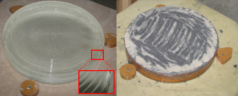
The blank disk, purchased from mirro-sphere is made of a type of glass called Suprax. It is slightly greenish in color. The surface is not flat: it bears the mark of a glass that was poured molten into a rotating mould. This techniques avoids air bubbles and reduce stress as the glass cools. The sides are not straight but were left as such and it turned out not to be a problem.
Grinding makes use of an artificial abrasive called silicon carbide. The grain used is C36 or C40 (like rough sand) and must be wet for better efficiency and to avoid glass dust. The position mirror-on-top results in eroding the center of the mirror. A generous chamfer must be maintained using a whetstone as any sharp glass edge is very fragile (movement towards edge, at 45 degrees) . The following steps are repeated until the abrasive is reduced to a smooth grey mud (one wet, ca. 3 times around the stand):
- about 6 up and down strokes
- rotation of the mirror by about 120 degrees in one direction
- move ahead one pace in the opposite direction
The random character of the movements contribute to eliminate possible repeated errors. Total time: about 30 hours.
2.3 Controls

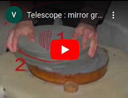
One way to measure the sagitta is to try slide coins from various countries in the center of the mirror below a ruler as illustrated above. In this project, the sagitta was reached after approximately 50 wets and 10 hours.
MIRROR: Smoothing
Objective : to obtain a spherical and smooth surface.
3.1 Tools
The same tile tool as for grinding is used and the table is raised to 108cm as there is less pressure to apply.
3.2 Process
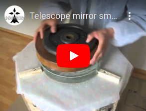
Finer and finer abrasives are used, making movements like an 8 and without applying pressure. We now alternate mirror on top and tool on top since we want to preserve the sagitta and not to "dig" anymore. Since the tool is much lighter than the mirror, a 5kg weight is placed on top of it when the tool is on top.
When switching to a lower grain abrasive, everything is very carefully brushed, washed, cleaned, rinsed and vacuumed like you're going to eat your next meal on it. You don't want a grain of a previous and rougher abrasive to stick around and ruin the surface and your time and effort.
- C60 - 60 wets - 5hrs
- C80 - 60 wets - 5hrs
- C120 - 60 wets - 5hrs
- C180 - 100 wets - 6hrs
- C230 - 50 wets - 4hrs
- C400 - 60 wets - 6hrs
- C600 - 10 wets - 1hr
- W9 - 14 wets - 1hr
Total about 30 hours, not included is the time spent cleaning up between abrasives.
3.3 Controls

The surface is checked using a magnifying lense after each series of wets (6 to 12) and we keep going with the same abrasive until no defects are found.
To test if the curve of the mirror is a sphere, a simple test is to draw a grid pattern on the glass surface with a waterproof felt pen and to do just one wet. If the lines are evenly worn out, it means the curvature of both mirror and tool match and make a spherical shape.
At the end of the smoothing process, after the finest abrasive, the mirror starts to be a mirror: it is smooth to the touch and reflects bright lights at shallow angles.
MIRROR: Polishing
Objective: a surface that is perfectly spherical, polished and reflective. We don't use abrasives as earlier, but a nanometer powder of cerium oxide which will "spread" instead of eroding glass. in other words, we "push" glass hills into glass holes.
4.1 Tools
 Stand: same table as earlier
Polishing tool: we need a new tool made of plaster instead of wood, with pitch squares instead of tiles.
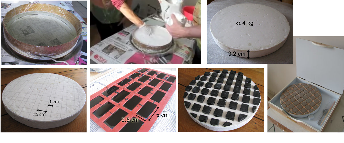
The plaster is called Staturoc (French denomination): it is dense, hard and most of all waterproof. Cooking oil is smeared on the mirror, which is then covered with 2 sheets of cling film, ensuring there are as few air bubbles as possible. A dam is wrapped around the mirror. A little parafin is smeared in the chamfer of the mirror to later ease the separation of tool and mirror and to make the dam water-tight. 940 ml of ice cold water are poured in and 4kg of plaster are sprinkled over. The first 2 kg sink in the water, then it starts accumulating on top. At this stage, mixing and breaking lumps is done by hand while the rest of the plaster is poured. This is a two-man-job: one keeps pouring the plaster, the other mixes (thanks to my cousin Xavier for the help). After 5 min, a smooth, homogeneous mixture is obtained. It is thick like yoghurt, but liquid enough to create a flat surface. The plaster sets within 15 min, and the dam can be removed after an hour or two. I waited 3 hours to separate the tool by gently sliding it across the mirror. The few dips you can see are due to air bubbles trapped between the cling film and the mirror.
Pitch is a nasty material. It comes as a bar of roughly 20x10x3cm, of which blocks are broken off and melted in a dedicated old pan (you really don't want to cook anything in there afterwards). The liquid pitch is then poured in the heat-resistant plastic mould shown in the photo (chocolate, anyone ?). Hot pitch is liquid, gives off awful, stinky, flamable vapors (better handle it outside), it becomes very sticky when it cools (watch your clothes), before becoming hard and brittle at room temperature (scattering bits and pieces all over the place). The blocks are then cut up with a hot blade. The tool is prepared to receive the pitch squares by drawning lines as illustrated on the photo and the surface is smeared with candle wax. The pitch squares are held above a candle flame just enough time to melt a little the surface, and they are then stuck on the tool.
So that the pitch squares have a surface that matches the surface of the mirror, they have to be pressed. This is done by placing the mirror on top of the tool, with a sheet of baking paper in between. The mirror can be warmed up to make it faster. I let mine at room temperature, and left it on the tool for about 4-5 hours. The squares that overhang or are too close to one another are cut a little. The tool now weights 5 kg (about the same as the mirror: perfect).
Storage box: the pitch tool must be kept clean of any particle susceptible to scratch the mirror. A dedicated box is build out of plywood. The brush used to smear the cerium oxide paste is also stored the that box.
4.2 Process
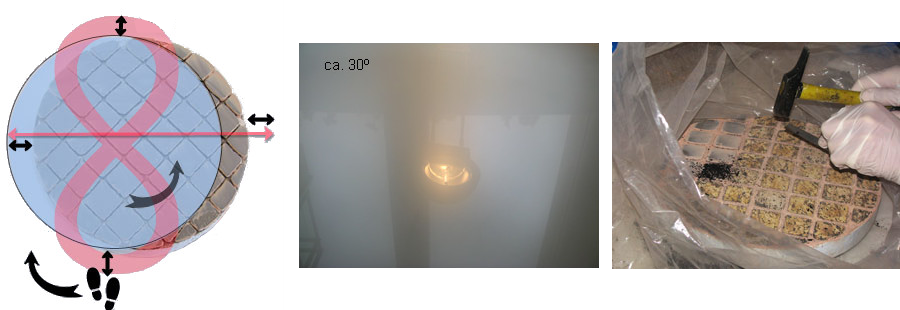
Cerium oxide powder is mixed with a little water and smeared on the pitch using a paintbrush. Polishing strokes are 8-shaped, slow, smooth, overhang 1/3 D, alternating MOT/TOT every 15 min. Adherence is quite strong, and the work takes much more effort than smoothing. Keep moving all the time otherwise mirror and tool may lock. The soft wistling sound is a welcome change from the loud SKRRR SKRRR of the rough grinding.
It is important to add cerium mix or just water from time to time, by just shifting the tool or mirror aside, no need to separate them. Over the course of the process, the pitch tiles get squeezed and spread. They MUST NOT touch each other: it is crucial to cut their edges regularly using sharp knife or a cutter blade. This is a messy job: the pitch is brittle, so make sure you protect the area against flying bits of pitch. If the pitch wears too thin, all that remains must be cleared and a new pattern must be laid.
As polishing progresses, the surface gradually becoming reflective, both at the center and near the edge according to the light-bulb test (angle 30 degrees). You can even see the reflection not only of a desk-lamp itself but also more and more of less bright objects.
Total time: about 50 hours
4.3 Controls
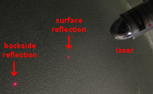
The surface state can be checked using a red laser (the toy of my neighbour's cat) : if the reflection on the surface is clearly visible (due to scattering of light), this means that the polishing is not finished.
MIRROR: Figuring (parabolisation)
Objective: a spherical mirror focuses light from a nearby object at the radius of curvature. However, only a parabolic mirror can focus light from very remote objects like stars in the sky. Therefore, the objective of this step is change the surface to a parabola, and this is a very lengthy, delicate and precise task. The surface should have a wavefront error smaller than Λ/10 (Λ is the wavelength of green light to which the eye is most sensitive: 500 nm).
5.1 Principle

The previous polishing step, if successful, gives us a perfectly reflecting polished surface, free of any defects, and also spherical. Now to transform this spherical surface to a parabolic surface, we need to deepen the center and flatten the edge ever so slightly. Specific movements (strokes) are required.
5.2 Tools

Pitch tool: no change, same as earlier
Foucault knife-edge tester: this device will let us check the surface of the mirror. The principle is explained in this wikipedia article.
- LED set in an adhesive rubber pad, stuck on the knife edge. A small piece of translucent (baking) paper is placed in front of the LED to make its light more even.
- the image forms about 3 cm above the LED.
- the mobile chariot is pressed against the focusing screw thanks to two rubber bands
- focusing screw moves the chariot forward or backward (it slides on the wooden stick visible on the mirror side image)
- this knob lifts or lowers the chariot, also moving the knife edge sideways in the process as it rotates around the horizontal axis (wooden stick visible on the mirror-side image)
- slit (used in a previous version, not necessary anymore as the LED is placed on the knife edge)
- removable plateform for the camera. The lense is placed as close as possible to the knife edge. Photos are taken using an exposure of 1.6s, F/4, manual focus, and zoomed so that the image fills the field of view
Mirror stand: this a sturdy stand that will hold the mirror in a vertical position. The mirror rests on rubber pads and is safely secured in position. It is placed at 3m (curvature radius) from the Foucault knife-edge, with no air movement in between (no heater, no window) since air turbulences will affect measurements.
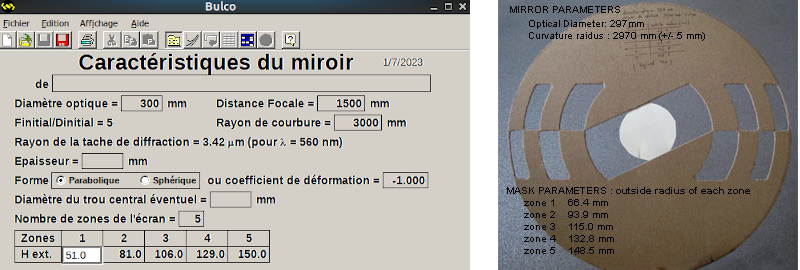
Couder mask: made out of cardboard, the mask defines 5 zones. A second mask was later built with 7 zones. Dimensions and positions of the zones were calculated using a French software called Bulco (not a recent software, but it does the job and it runs in Wine on Linux).
5.3 Process
If after reading the previous steps, you think it's taking ages up to this point, don't hold your breath for this step either... Figuring (aka parabolisation) is the longest and most delicate step, although experienced users are able to reach the ideal parabola much faster. This step took me way more time than all the previous steps combined.
The starting condition is that the mirror has a spherical shape. This can be checked using the Foucault device. The knife edge to must be exactly at the radius of curvature. Moving the knife edge sideways will cut the light over the whole mirror and it should dim evenly the whole surface (all white to all grey to all dark). Also, the surface should be free of defects such as irregularities, bumps, scratches...).
Figuring consists in making specific strokes and regularly taking measurements. This really is a process where having advice from experienced colleagues is important. There are several types of strokes, which can be performed mirror-on-top or tool-on-top. After each set of strokes, the mirror is rinsed, dried and carefully placed on the stand. Using a laser placed on the Foucault device, you have to find the reflected spot of light, and then adjust both the Foucault device and the stand so that the reflected spot of light hits the knife edge.

5.4 Controls
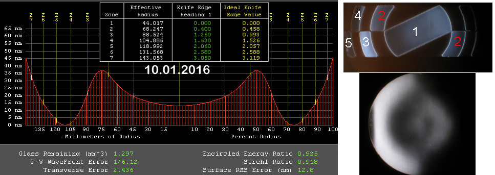
Starting either from the inside or the outside zone, move the chariot forward or backward and move the knife-edge sideways so that the zones left and right are evenly grey and record the dial gauge position. Then repeat for each zone and log the results in a software such as FigureXP (which also runs on Wine if you are a Linux user). You obtain a extrapolated representation of the surface.
It is also important to check the overall surface quality by removing the mask: the surface should be smooth, free of scratches, bumps or pits.
5.5 Result
After months of work, I managed to get quite close to the ideal parabola but I could not get it right. Eventually, I decided to send the mirror back to Mirro-Sphere for the end of the process and for the coating. The mirror came back with an excellent surface quality and with a 96% reflective coating based on Al + SiO2 + TiO2. Note the small triangular sicker placed exactly in the center by the service who did the coating. This mark will be useful when collimating.

PS: you could say "why bother with all this work ? why not simply buy the mirror ?". Well, it's like travelling: the objective is not the destination, it's the trip in itself: it's everything you learn on the way.
STRUCTURE: Primary Box
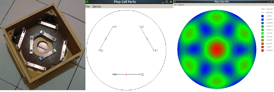
The primary box is made of plywood with a hole in the bottom to fit a fan that might help in cooling the mirror.
Dimensions: 36 x 36 x 20 cm (thickness 1.5 cm)
The mirror cell is calculated using a software called Plop (Windows only, but it runs fine with Wine on Linux). It's a brilliant piece of software: give it your mirror diameter, thickness and focal length and it works out the surface deformation for a given number of support points. In this project, 6 supports point are enough: they are arranged on 3 aluminium U shaped bar that can freely pivot on a central point.
The mirror is held in place by 4 other aluminium U shaped bars. On the end of each bar, a small aluminum square tube is attached vertically. A nylon screw is driven through those tubes and the tip touches the mirror edge. This system spreads the weight of the mirror equally when the telescope is tilted towards the horizon. Another set of nylon screws is inserted so that the tip hangs just over the chamfer of the mirror (to prevent the mirror moving if the telescope is tilted too much, but in fact, this is unlikely).
The base of the mirror cell is made of a denser and harder type of plywood. One point (middle bottom on the image) is fixed, two other points (top left and right on the image) can move up or down on a lead screw for collimation. The lead screws can be turned from the top (much easier than from below the box - see further down "FIRST LIGHT: collimation").
STRUCTURE: Secondary Box
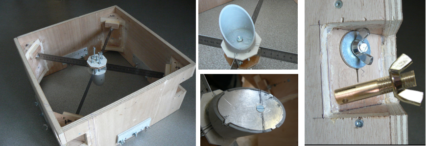
The secondary box is also made of plywood, slightly larger than the primary box so that when unmounted, it can fit on top of it. The spider vanes that hold the secondary mirror are simply made out of a 40 cm stainless steel ruler. They can be tightened thanks to butterfly bolts.
Dimensions: 38.5 x 38.5 x 20 cm, thickness 1 cm
The secondary mirror was purchased from mirro-sphere: this a eliptical flat mirror (small axis 67.5 mm).
The secondary mirror holder is made from a truncated PCV tube (50mm diameter). The truncated side is covered with an aluminium ellipse, which is bolted in place. The secondary mirror is stuck on the aluminium with aquarium silicon glue, with a 1mm space. The mirror can be titled by adjusting 4 screws that push on the base of the PVC tube.
A 50 mm hole is drilled where the focuser will later be positioned. On each side are prepared attachment points for the square aluminium tubes of the serrurier truss.
STRUCTURE: Serrurier Truss
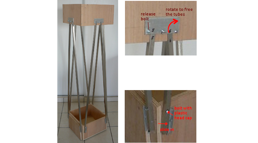
The structure holding the primary and secondary boxes together is called a Serrurier single truss. It provides rigidity and keeps optical elements aligned, no matter the tilt of the telescope. For larger, heaving telescopes, a double truss is preferable but it is not necessary here.
Dimensions: square tubes are 1.5 x1.5 x 125 cm. The space between primary and secondary box is 106.5 cm.
A hole are drilled near bottom of the tubes so that they slide onto a bolt protuding from an aluminim U-shaped guide. A bolt with a plastic head cap is used to secure the tube in position. Likewise, a hole is also drilles neat the top of the tubes, which also fit onto a bolt. The tube is then held in place by an aluminium flat bar which rotates into position.
The system at the top is perfect: it's quick to setup but securing the bottom of the tube takes a little too long.
STRUCTURE: Rocker
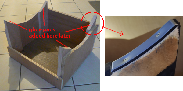
The rocker is build as a box made of plywood. Two sides will support the primary box semi-circle bearings (see later) on glid pads (not shown). The back side on the image will later be modified: a opening will be made so that the whole thing is a little lighter and also to allow access to the inside where the electronic will later be installed. The front side on the image is lower as the primary box will need space to move when the telescope points down towards the horizon.
Dimensions: 47 x 42 x 25 cm, thickness 1.8 cm (supports are 2 cm thick and the top is 7cm above the top of the box)
STRUCTURE: Balancing
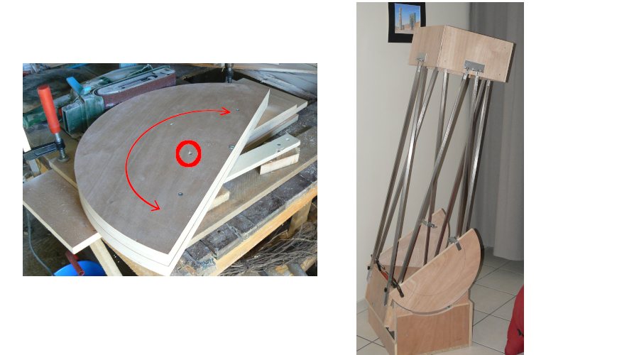
Side bearings are cut out of plywood with a jig-saw and shaped to perfect identical semi-circle by running them against a belt sander as illustrated above. This is a loud and dusty job !
Dimensions: diameter 54cm, thickness 2cm
With the mirror installed (and protected !) in the primary box, the semi-circle bearings are clamped to the aluminium square tubes at the correct height so that the whole setup is balanced even when tilted down. The objective is that rotating axis of the bearings is at the center of gravity of the primary + secondary box. However, the glide pads add friction and this is not very accurate. For more precision, the same experiment can be conducted by driving a tube through the center of the bearings and balancing the telescope between two chairs (no image, sorry). Ideally, bearings should be positioned slightly higher since extra equipment will later add weight to the secondary box (eyepieces, focuser, laser....).
STRUCTURE: Azimut Disk
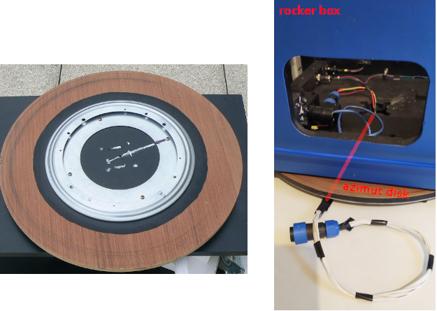
The rocker rests on a rotating disk (amazon "lazy susan on ball bearings"). 4 bolts protruding from the rocker fit in the holes on the rotating disk. Glide pads were later added on the rocker underside, on each corner, for better stability. The "lazy susan" is attached to the azimut disk, cut out of plywood. The edge is made perfectly circular using the same technique as explained earlier with a belt sander for the bearings and a GT2 belt (like for 3D printer) is glued on its edge. The surface is smeared with mineral oil rather than painted, so that the pads attached at the bottom of the rocker can glide around it as the telescope will go around its azimut axis.
A split ring was later fitted in the center of the azimut disk, so that 12V power and sensor signal can be delivered to the electronics located in the rocker box. This means that the rocker box and azimut disk are always kept together.
Dimensions: 50 cm diameter, 1.5 cm thickness
Results: movement is really smooth, however later tests revealed that when it's cold outside, it tends to grip (the metal contracts ?). Also, in the long run, dirt might accumulate in the bearings. Ideas for a better solution using PTFE are in the pipeline.
STRUCTURE: Focuser
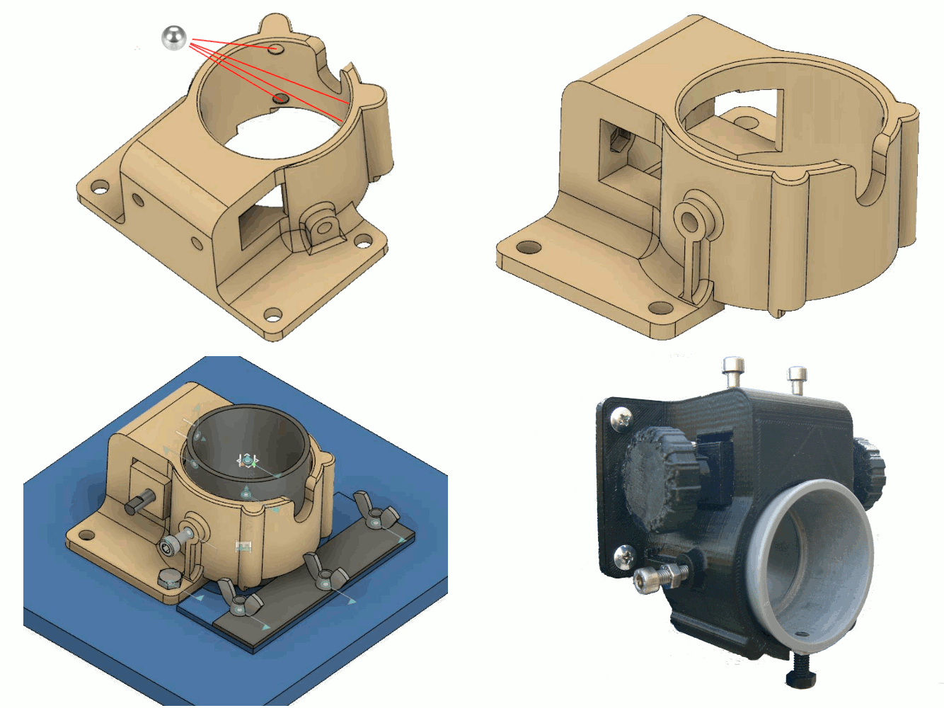
The Crayford focuser was 3D printed (credits to Jérôme, brother-in-law) after modifying a design found on the web (<file on github - link to be added>. Unfortunately, I cannot give credits as the web page seems to have been removed). The tube that will hold the eyepieces is simply a 50mm PVC junction that required a little sanding on the inside (eyepieces are 2 inches, which is 0.8 mm more). A small strip of bicycle inner tube was glued on the top of the PVC tube for better grip by the focusing rod (unpolished aluminium), to which 2 knobs are attached. The bolts on top push the focusing rod against the PCV tube. The bolts below and to the left meant to secure respectively the eyepiece and the PVC tube in position turned out to be un-necessary.
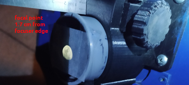
Results: the focuser works great. The 2 bolts on top, which press the rod against the rubber strip on the PVC tube, should not be tightened too much so that the PCV tube moves smoothly. The 4 bolts that attach the focuser to the secondary box allow for a degree of movement in order to manage the tilt. Also, the focal point is well positionned at 1.7cm outside the focuser which leaves not a lot but sufficient back-focus to fit a camera.
STRUCTURE: Finishing Touches
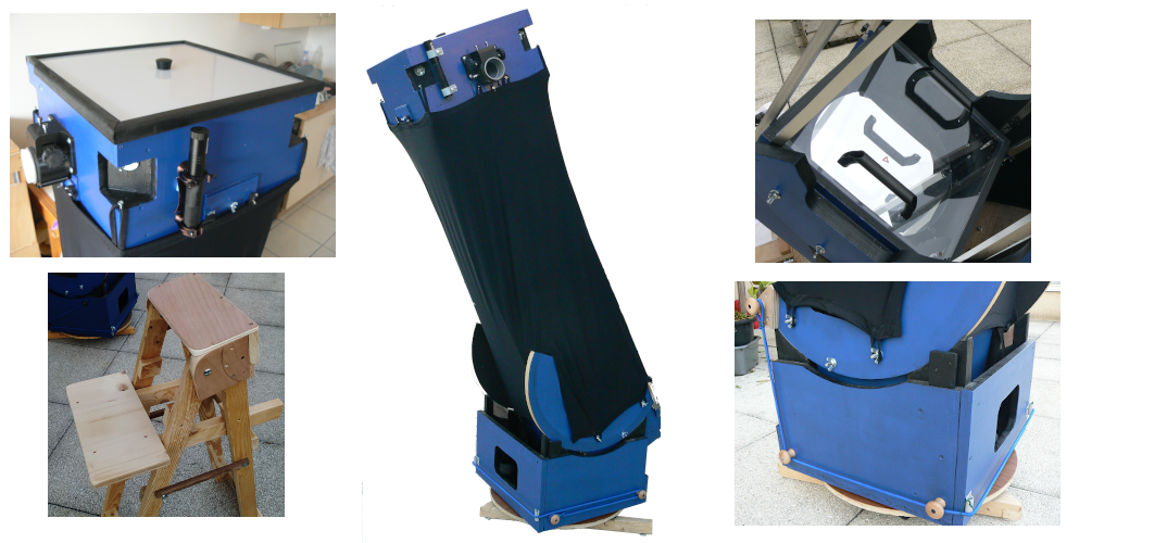
- paint: All external wooden surfaces are painted blue except the edge of the bearings and the azimut disk which are smeared with mineral oil. All internal surfaces, including the aluminium square tubes of the serrurier truss are painted black.
- lid on primary box: A transparent plexiglass lid is cut to the size of the primary box in order to protect the precious primary mirror from dust.
- straps with carabiners: 2 straps are installed under the primary box with loops at the ends. Another pair of straps with carabiners can be attached to the loops. This system allow to lift the telescope (primary box + truss + secondary box) in and out of the rocker and to carry the whole thing on a short distance (between apartment and outside).
- lid on secondary box: A lid is fitted on the secondary box: it is cut out of translucent plexiglass in anticipation of the flat images used in astrophotography processing (flats are images taken with an evenly distributed source of light, and are essential to correct uneven sensor illumination, vignetting, dust specks etc... in the optical field)
- lycra skirt: who would have guessed that sewing skills can be useful when building a Dobson telescope... A "skirt" made of black lycra (a fabric that can stretch) will help protect from unwanted light and dust. Small loops made of shoelaces are sewn at the top and bottom: they attach to screws and bolts to hold the skirt in place. Velcro bands were added wherever there were gaps between the lycra and the primary box.
- bungee cord: it turned out that the telescope is not well balanced and has a tendency to tilt downwards: instead of adding weight at the bottom of the primary box (the whole thing is heavy enough), a bungee cord is attached to the end of the bearings. As the tilt increases, the tension increases and perfectly compensates the lack of balance.
- laser: a 50 mW green laser is mounted on the secondary box and aligned with the telescope. This makes it so much easier to aim the telescope at any object in the sky. The top of laser can be adjusted with 3 screws in a PVC pipe holders.
- observation seat: finally, an adjustable seat is build out of palet wood and plywood. This makes visual observation so much more comfortable.
STRUCTURE: Transporting
1- Pack it and move it
The telescope can be packed for transportation. The skirt is pulled down. The latches are rotated up, then each aluminium tubes is released and shifted sideways, so that the secondary box just rests on them. It can then be easily lifted up and moved aside. Latches must be closed. Once the aluminium tube are removed, the secondary box fits on top of the primary box. The aluminium tubes are rolled one by one in the skirt so they don't rattle and the black paint is preserved.
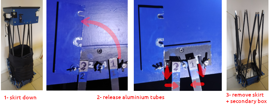

Result:
It's heavy: we're not talking about a super-light Dobson that fit in a suitcase. The process takes about 15 minutes. The primary + secondary box together weight 17 kg and fit in the boot of the car along with the rocker (13 kg) and the equatorial table (see later, 11 kg). With a total of over 40 kg in several pieces, it's a bit of an expedition when I drive to the local observatory, away from light pollution.
2- Just take it outside
The telescope is usually stored in the appartment, ready to observe. To take it outside, straps are fitted and the whole telescope can be lifted and carried with much care passing steps and doors.
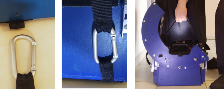
Result:
The straps are convenient and the hands being just above the center of mass, it's reasonably balanced (no tendency to tilt). It's heavy to lift and delicate to go through doors (the top of the telescope is centimeters below the door frame). Once outside, it is fairly easy to slide the telescope down into the rocker box.
FIRST LIGHT: Selection of Eyepieces
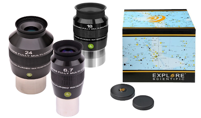
A selection of eyepieces was purchased at the only store in Brittany: astronome.fr in Lorient. All eyepieces have a 82º field of view (when observing, you don't see the edge of the eyepiece since the human eye has only a 70º field of view).
- 24mm: 62x magnification / wide field of view (almost 1º) and is great for deep sky objects.
- 18mm: 83x magnification, great for globular clusters and deep sky (I think 14mm would have been better as it is too close to the 24mm)
- 6.7mm: 220x magnification, great for Moon and planets
Buying the range of eyepieces from the same manufacturer is important as it guarantees only small differences in eyepieces focus positions.
FIRST LIGHT: Collimation

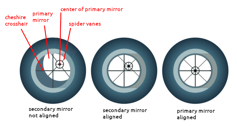
A Cheshire is a simple device made of a tube with a peephole at one end, a crosshair at the other and in between, a shiny face set at 45° to the barrel and exposed through a hole in the side. The Cheshire is inserted in the focuser and helps in collimating the optics. This device can be purchased but it is also simple enough to make at home using a PVC tube.
Dimensions: 50mm diameter, 18 cm length.
- start with the secondary mirror: adjust position and tilt so that it appear circular (not eliptical) and centered
- adjust the collimation screws of the primary mirror so that the center of the mirror marked with the sticker, the crosshair and the spider vanes are all perfectly aligned
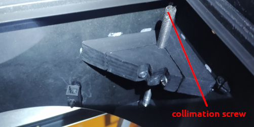
Finally, the collimation should be fine-tuned by pointing to a star with a high magnification eyepiece, slightly out of focus. This should be done in good seeing conditions with as little turbulences as possible. You expect to see rings which should be perfectly concentric and circular when the telescope is well collimated.

In my case, the collimation with the Cheshire was spot-on (not bad for my first time collimating a telescope).
FIRST LIGHT: Visual Observations
The telescope saw its first stars in early July 2018: just randomly navigating through the Milky Way or around the craters of the Moon is amazing. The optics are excellent: the image is sharp and the handling of the telescope is pretty good. However, the altitude bearings have too much friction: they need some resistance but in this case, I have to push a little hard to get it moving, then it suddenly moves too far. This makes observations at high magnification a little difficult and will require a fixdobson later. Balancing is acceptable (with the bungee cord in place).
Messier objects are clearly visible thanks to the 300mm diameter. I could see really well the comet Neowise in July 2020 (although the field of view was too small for such an object, even with the 24mm eyepiece).
The focus position of the 3 eyepieces differs by only 7mm and is well within the range of the focuser. I made markings on the PVC tube so that I can quickly focus close to the correct position.
Very satisfied, it was worth the time and effort.
EQUATORIAL TABLE: Construction
Principle: Since a Dobson telescope is based on an ALT-AZ design, it lacks a polar axis and therefore is not capable of following an object in the sky as the Earth rotates. The objective of an equatorial table is precisely to offer this feature, although it will only have a limited angular (and time), which is about one hours / 15 degrees.

Design: The difficult part in the design of an equatorial table is the balance: the center of gravity of the telescope should be on the polar axis of the equatorial table. If it is too far above or below, the motor may struggle to drive the platform effectively.
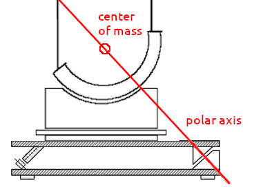
Another criteria is the need for sufficient space between bottom and top boards for the power supply and the arduino that will drive the motor. The two rails on the top match the width of a square piece of plywood underneath the azimut disk: this ensures I always place the whole thing well centered on the equatorial table.
The semi-circle segments are made with a sand belt. They are installed with an angle that matches the location latitude. A flat aluminium bar was screwed on the main segment edge to make it more resilient to the weight of the telescope. The wheels were later replaced for better ones with ball-bearings. When not in use, I do not leave the telescope on the equatorial table as the weight might dent the wheels over time.
Dimensions: 63 x 40 cm. Space between top and bottom 15 cm. Segment diameter 47.4cm
Result: The equatorial table allows about one hour of tracking. However, it is not perfectly balanced: at certain positions of the telescope, when I move it by hand, I have to push more in the direction the motor will go than in the opposite direction. The center of mass is indeed slightly above the polar axis.
MOTORISATION: Equatorial Table
The first attempt by friction turned out to be unreliable: at certain positions of the telescope, the weight to push was too much and the axle pressing the wheel would just slip. Also, the stepper was held in a wooden casing which left too little air around it, and it tended to get quite hot. This system was first replaced by a trapezoidal lead screw directly driven by the stepper, which proved much more reliable, and later by a ball screw for less friction.
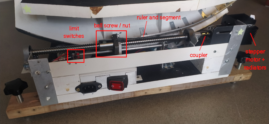
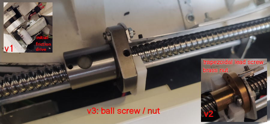
The ball screw and ball nut (and other accessories were purchased on AliExpress). The lead screw SFU1204 has a lead 4 mm, length 350 mm. Limit switches stop the motor when it reaches the end position. It is easy then to "rewind" the equatorial table.
The stepper motor was purchased on robotshop.com: it has a step angle of 0.18deg, it is sold with a 100:1 reductor. To improve cooling, atwo 4x4cm radiators are attached on it. The stepper rotor is carefully aligned and connected to the lead screw with a rigid connector. A PTFE piece slides on an aluminium guide to prevent rotation of the ball nut.
The 220V power connector is located in a small PVC housing below the lead screw. The cable runs underneath the bottom board and reaches the 220V -> 12V power supply (144 W).
Result: tracking works well for visual and for up to 20s at best for astrophotography. The lock bolt is a little small but it does the job.
ELECTRONICS: Equatorial Table
Air flow and humidity protection: A "3-floor" kind of box (16x10x10 cm) was built out of PVC with a plexiglass cover to keep all electronics out of harm from humidity. A heating element (polyimide 12x39mm 12V 4.5W from AliExpress) was stuck on a small aluminium flat bar and positioned above the air intake (right-side of the box). In case of high humidity, this raises the temperature of the air above the dew point before it reaches the electronics, avoiding the risk of condensation. The air moves below the power supply to a fan that pushes it down into the compartment housing the Arduino, the DHT22 air and humidity detector and the bigeasydriver board. The air then exits at the back, goes through the power supply and is pushed out by the fan installed on the cover.
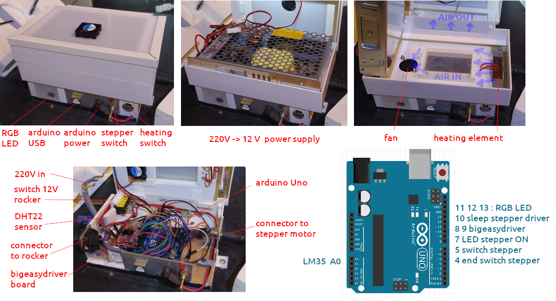
The front of the box is readily accessible: a RGB LED changes from blue (cold) to green (warm) to red (hot) according to the temperature of the bigeasydriver chip (which tends to get hot even with a radiator on it). The sensor is a LM35. An up/down switch controls the motor and a push switch controls the heating element.
The left side of the box has a connector with 5 wires going to the rocker split-ring: 2 for power (12V and GND), and 3 for the DHT22 sensor. A switch controls the power supply to the rocker.
The right side of the box has a 8-pin connector: the cable goes to the stepper motor and to the end switches.
The code of the Arduino is published on GitHub.
Result: for visual observations, this setup works great. At high magnification, the Moon, Jupiter, Saturn etc... stay perfectly in the field of view. This is a major improvement and makes all observations much more enjoyable. The heating element plays its role perfectly. Even though the equatorial table is not perfect, the stepper nevertheless manages all right (well, with the lead screw system, it has no choice anyway...).
MOTORISATION: Rocker: Alt Axis
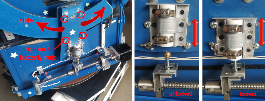
The ALT axis motorisation is achieved thanks to a second semi-circle bearing, onto which a contraption with two half-bolts at the bottom can slide and be tightened as desired. The ball screw (4mm lead) is fixed and a brass ball inserts into a PTFE tube to lock the ALT axis of the telescope. The stepper is a Nema17 with a step angle of 1.8º. The ball nut is kept steady thanks to a fixed rail. 3 end switchs cut power supply if the ball nut nears the end of the screw and if the scope comes at maximum vertical position.
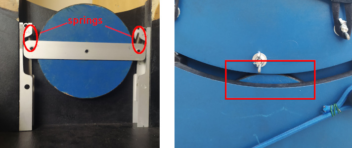
Also, in order to reduce friction on the glide pads, the bearings rest on two disks, which are "suspended" thanks to strong springs. The spring take some of the weight of the telescope and make the ALT movement significantly smoother. When the telescope is in place, the disks sag from 2 cm down to less than 1 cm.
Result: this setup works pretty well. Movement is smooth, yet there is just enough friction so that it does not move all by itself. The motorisation lock and unlock system is not pretty but does the job. The segment can be easily moved up and down its dedicated semi-circle bearing and tightened in position. The combination of direct drive with no reducer and the two half-bolts result in quite little backlash.
MOTORISATION: Rocker: Azimut Axis
After several earlier attempts that proved unsatisfactory (lack of grip, backlash), I settled for the similar principle as for the alt axis: a ball screw (4 mm lead) inserts between two PFTE blocks with a direct drive (stepper Nema 17, step angle 0.9º). The assembly stepper + lead screw can be flipped over: this gives access to the white piece of wood which is held tight on the azimut disk thanks to 2 butterfly nuts.
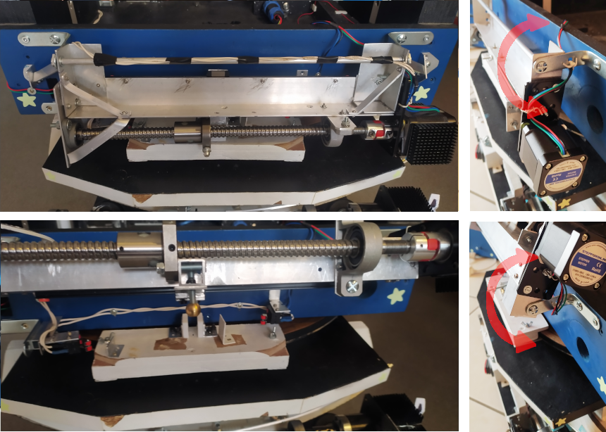
This setup gives sufficient movement in azimut. End-switches cut power to the stepper coils before the rocker rotates into the PTFE blocks. The structure is reinforced to make it sturdy.
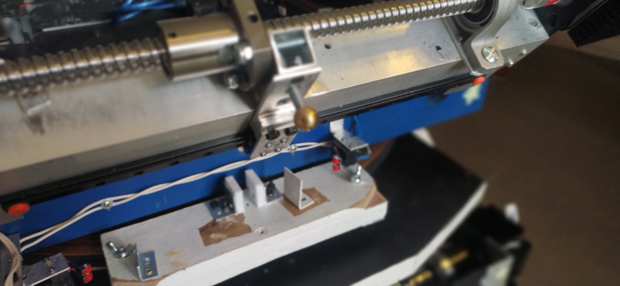
The image below shows the underside of the white piece of wood (hmm... the aesthetics have been neglected...). The black irregular bits are rubber pads cut out of an old bicycle inner tube and ensure a good grip on the azimut disk. A section of a 3D-printer belt is glued on the inner edge which has the same curvature as the azimut disk (which also has the same type of belt glued all around).

Result: reasonably quick to setup. I like how the stepper + lead screw assembly flips over. Satisfied.
MOTORISATION: Secondary Box: Focuser
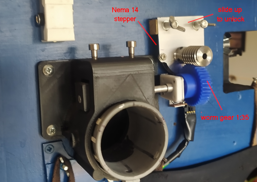
An initial motorisation was built using a stepper motor type BYJ48 but it proved unreliable when cold. A very light (30g) Nema 14 stepper motor (omc-stepper-online.com) was later installed, connected to the focuser shaft thanks to a 1:35 worm gear (ali express). For coarse focusing, un-tighten the two butterfly bolts and slide the stepper assembly up. With the assembly down, fine focusing can be done both manually and with the stepper. A cable connected to the Arduino pins and running along one of the truss aluminium tubes sends control signals to the stepper.
Result: This system is very satisfactory and fine focus is very very precise.
ELECTRONICS: Rocker Alt Az Focus Sensors
Housings: The Arduino Mega, Odroid N2+ and connectors are encased in PVC boxes (11 x 11 x 3 cm) which are stacked in a corner of the rocker box. Here you can see one good reason besides the specs why I choose the Odroid N2+ : all its ports (Ethernet, HDMI, USB, power IN) are at the front and can be easily accessed.
Split-ring (aliexpress): The cables from the split ring bring the 12V power and the signal from the DHT22 temperature and humidity sensor from the equatorial table PVC box housing the electronics. The split-ring cables are connected to a sidebox thanks to the big blue/black connector. From this point, the 12 V is distributed to the Odroid, the Arduino, the fans and the stepper drivers.
Connectors: the box above the Odroid is equipped with two 12V output jack connectors and one 8 pin connector for the focuser. Those connectors are easily accessible through the rocker opening as illustrated below.
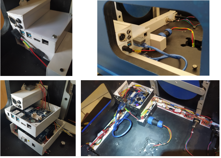
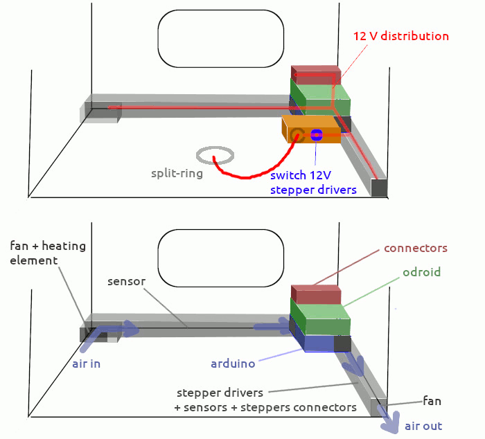
Air flow: a fan pulls the air in, over a heating element (controlled with a manual switch just on the top of its box), into the conduit, passing over a DHT22 sensor. The air continues into the Arduino housing (cooling the Odroid as its radiator is attached to its underside). The air then exits, pushed out by another fan after passing the stepper drivers and 2 sensors (DHT22 and LM35 stuck on radiator on one of the stepper driver chip).
Electronics: all sensors and motor control cables are connected to the Arduino pins. A USB cable connects the Arduino to the Odroid. Both are powered from a 12 V jack cable. The stepper drivers (ULN2003 for the focus and bigeasydriver for the AZ and ALT) are powered on 12V. Everything has a common GND.
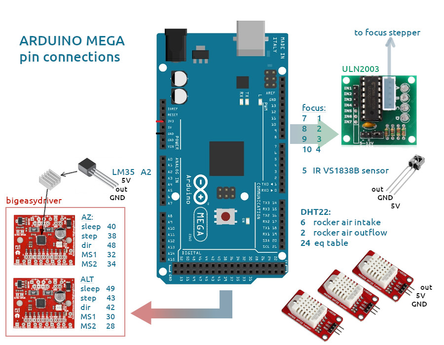
Code: the Arduino and Python codes and the Odroid N2+ configuration are detailed on GitHub. Basically, the Arduino does what Python or the IR remote tells it. Python provides a graphical interface to control the motors and to take images. See "controls" further down.
Result: this layout is about as practical as it was intended to be. The 2 fans provide sufficient air-flow so that there's no overheating. When there's a risk of humidity, the heating element does a great job to raise the temperature by 5-10 degrees, bringing down the relative humidity from over 90% down to 50%. Connectors are reasonable easy to reach through the rocker opening. Everything is modular and can be easily taken apart for maintenance. All the surfaces were later painted black to minimize stray light coming from various LEDs in the rocker box towards the optics just above. When the telescope is tilted, the rocker box passes just one cm above the PVC housings: tight but just right!
CONTROLS: Infra-red Remote
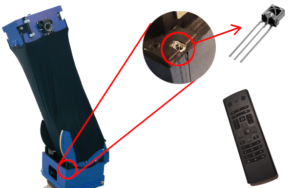
An InfraRed sensor type VS1838B (aliexpress) was installed in a corner of the rocker on the same side as the user would be when doing visual observations and connected to the Arduino Mega.
Writing the code requires that you first obtain the hex numbers generated from an IR buttons, see projects such as this one for further details on this simple process.
The code I have written provides the following features:
- control ALT and AZ stepper motors in both directions with the arrow keys
- control speed by pressing 1 (slow), 2 (normal) or 3 (fast), then an arrow key
- control focus using P+ or - for slow and V+ or - for fast
The code I have written is available on Github.
Result: I have not seen another telescope controlled with an IR remote. Note that the IR works by sending one pulse at a time, and does not provide a continuous movement. It is not meant for long displacements but rather for small adjustments. It is particularly well suited to viewing the Moon: move a little, enjoy the view then move a little more. Also, it's great to have no cable dangling from the telescope.
CONTROLS: Python Interface
Two Python3 scripts have been developped in order to control the telescope from the Odroid N2+:
- "dobson control" => ALT, AZ and focus stepper motors + display sensor values
- "solve and goto" => find image and target coordinates, calibrate the telescope and move to target
The Odroid is joined to the WiFi network (thanks to a dual-band WiFi dongle: no built-in WiFi card) and can be accessed over SSH or VNC.
Why Odroid ? There are many mini-computers on the market (most famous is Raspberry Pi). The Odroid N2+ by Hardkernel was selected for the following reasons:
- all ports on one side
- good specs
- positive experience with an earlier model
- affordable
- well documented + active community
- 4 USB-3 ports
Why Ubuntu ?
- Hardkernel provides ready-made images that include all Odroid drivers
- most of the software I will be using are available for Ubuntu
- it's a well documented, very popular and trustworthy distribution
Why Python ? why note C or Java ? ... well:
- easier to learn in my opinion than C or Java
- many libraries including: ZWO camera, serial communication, graphical interface
- very well documented
- I also need it to complement the Bash and PowerShell modules that I currently teach to sysadmin students
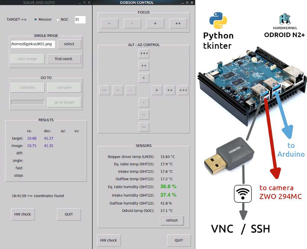
DOBSON CONTROL
- focus (2 speeds)
- move ALT and AZ motors (3 speeds) by a number of steps defined in the Arduino code
- request and display sensor values (humidity turns orange then red above 80 and 90% respectively)
- detect if Arduino is connected: if not, display message and disable all buttons
SOLVE AND GOTO
- get user input of a target (select catalogue and reference number)
- take or/and a single image (thanks to camera-asi-zwo)
- get the sky coordinates of this image (thanks to astap)
- calibrate the telescope (the user must first manually move and point the telescope as near as possible to the target, then the script moves the motors several times, taking and solving images each time and works out how many ALT and AZ motor steps correspond to how many degrees in sky coordinates)
- compare telescope position and target coordinates
- automatically move to the target by a number of steps calculated in Python and send to Arduino
- detect if the camera and the Arduino are connected, if not disable buttons and display a message
The code is available on GitHub.
Results: very satisfactory. The interface proves very handy. I have made several updates it over time (buttons are disabled when hardware is not detected, control buttons change while motors are moving, ....) and there will probably be more improvements in the future. I noticed that the display when X11-forwarding the GUI over SSH lags a little at times compared to VNC (perhaps due to the SSH encryption overhead). Also, it is crucial to have a dual-band WiFi connection (I changed my box and it made a very appreciable difference).
Side-notes about Odroid Ubuntu configuration:
- I configured the Odroid so that it can be started and shutdown by pressing a small button connected to a GPIO. See this Odroid Wiki for details. In the Ubuntu Mate GUI, I configured "press button" = 'shutdown' instead of 'ask'.
- auto-login is configured: /usr/share/lightdm/lightdm.conf.d/60-lightdm-gtk-greeter.conf => [SeatDefaults] => greeter-session=lightdm-gtk-greeter, autologin-user=<username>
- a static IP is configured on the Odroid ethernet interface for easy access in case it does not connect to the WiFi
ASTROPHOTOGRAPHY: HD Cam Behind Eyepiece
For fun and for testing purposes rather than actual high-quality astrophotography, I bought from amazon a small HD camera module on PCB:
- resolution: 1920x1080 px
- speed: 30 fps
- field of view: 77 degrees
I mounted it in a PVC tube that can fit on my 6.7mm eyepiece with the intention of having a an alternative to using my smartphone (which gives pretty good pictures of the Moon but it's very difficult aim and keep steady while the autofocus and auto-exposure do their job, then shoot).
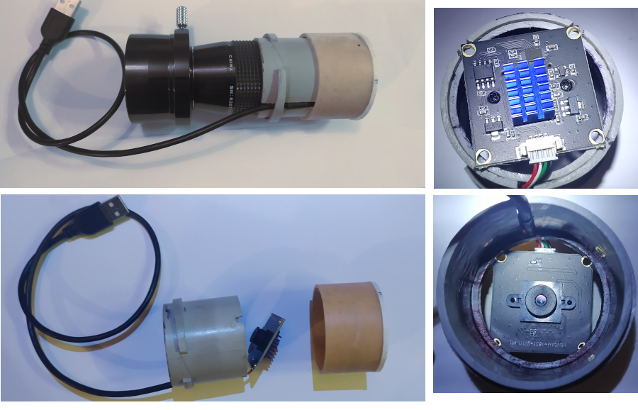
Since the PVC tube was slightly too small in diameter, I cut it on its side, which is in fact very helpful as it stretches open and holds firmly onto the eyepiece. This also allows space for the cable, which is held in place by a ring of PVC.
Results: The camera is recognised by GUVCview running on Ubuntu on the Odroid. I could take shots and videos of the Moon and of Jupiter. It is no substitute for a planetary webcam but it's a cheap and quickly made device.

ASTROPHOTOGRAPHY: Deep-sky Camera
Camera
After discussions with the astrophotographers at the astronomy association, after reading through some feedback from users in various forums, I settled for the ASI ZWO 294MC pro:
- it's a colour camera and great to begin with astrophotography
- it's cooled, which will help in long exposures
- photos taken by users are absolutely stunning
- ZWO is a well-known manufacturer with a reputation for quality
- it is compatible with the acquisition software (kstars / EKOS) I intend to use on Linux Ubuntu
- there are python libraries that allow imaging with this ZWO cameras
- only 0.5 cm back-focus (how deep is the sensor in the camera)
It is sold with a black flat USB cable type-B 3.0-male to Type A-male. The white cable is the 12V power supply (standard jack connector). Both run along one of the truss aluminium tubes, well hidden under the lycra skirt (no dangling cables I told you..) down to rocker box to the 12V output and to the Odroid USB-3 port respectively.
Baffle
Stray light may hit the sensor from the opposite side of the secondary box and spoil long exposure images. To limit this problem, I have built a baffle out of a light, thin, black foam sheet. It is held by two PVC 1x1cm angle bars which clip on the outside and inside of the secondary box. The baffle is 23cm high and only weighs 56g.

Software
There are many solutions for image acquisition. I settled for kstars / EKOS for the following reasons:
- it installs on Ubuntu
- very rich in features (even if I won't be using many of them)
- compatible with the camera (well, most software would be, since ZWO is well known)
- it's based on Indi which is a client-server driver: this means I can launch the server on the Odroid, and connect using the client on my laptop. It can then save images either on the laptop for processing or on Odroid. This is an interesting alternative to imaging via VNC.
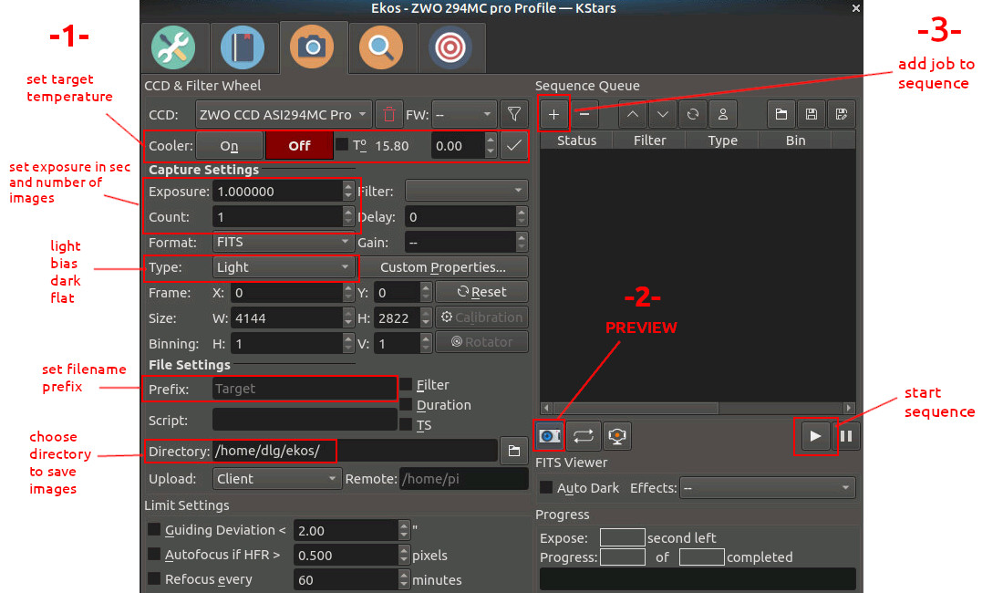
ASTROPHOTOGRAPHY: Images
Acquisition
Deep sky photography consists in taking long exposures in order to collect more light from faint objects such as nebulae and galaxies. Taking multiple exposures will help improve the signal to noise ratio as all images will be stacked during the processing phase.
The actual images of deep sky objects (called "lights") must be calibrated by acquiring:
- bias images: base level of read-out noise (cap on, shortest possible exposure, 50 – 100 frames, same temp as lights)
- flat images: correction factor for each pixel to take into account vignetting, dust etc.. (evenly illuminated light source, same gain, temp as lights, about 20-30 frames, histogram about 1/3 to 1/2 of full value)
- dark images: thermal noise of the sensor (cap on, same gain, temp and exposure as lights, as many as flats)
For flat frames, I put the translucent lid on the secondary box and point the telescope to the ceiling or to a cloudy sky.
Processing
I use the software SIRIL to process my photos. There are alternatives but they are not all open-source and not available on Linux. All images should be saved in a folder with the following subfolders.
- biases
- darks
- flats
- lights
I follow the process described in the following tutorial: https://siril.org/tutorials/tuto-scripts/
Limitations
With the current setup, I found that exposures longer than 30 seconds are not useable: the tracking is not good enough (stars are trails, not dots). Also, the telescope is quite sensitive to the wind, so I'll need very still nights for astrophotography. Another point of attention is the focus as it's currently not optimised. Finally, light pollution is a problem where I live, so I will most probably purchase a filter in the near future.
Publishing
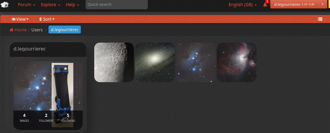
Images can be published online on any photography website but the one most specialised, most popular and selected by many of my colleagues at the association is astrobin.com. This is where I publish my results:
https://www.astrobin.com/users/d.legourrierec/
ROADMAP
So .. what's next ?
This might be the end of the instructable page but it's not the end of the project. Here are the plans in the short term:
- configure automatic focusing (more Python coding...)
- make the most of its capabilities with the most accessible deep sky objects (brightest Messier and NGC nebulae, galaxies, clusters...)
In the longer term, I plan to install a guiding scope and write some code for auto-tracking (I cannot use the PHD2 feature of EKOS as my Dobson is not a commercial scope, and I'm not good enough in software development to write drivers)
POWER CONSUMPTION
With the equatorial table stepper motor driving the telescope, the camera connected and temperature cooler ON, the power usage is around 38 Watts*.
If either the ALT or AZ motor is moving, power usage peaks at 55 Watts*.
Both heaters ON add another 15 Watts: the maximum consumption is 70 Watts.
(the power supply is rated at 144 Watts)
*these measurements were taken using a wattmeter plugged on the 220V power socket.
