Building an ISS Pointer Tracker Using Adafruit HUZZAH ESP8266
by rgrokett in Circuits > Arduino
17863 Views, 165 Favorites, 0 Comments
Building an ISS Pointer Tracker Using Adafruit HUZZAH ESP8266
Overview – Part 1 Alt/Az Pointer
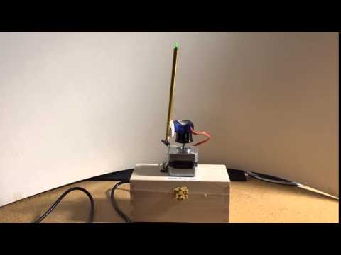
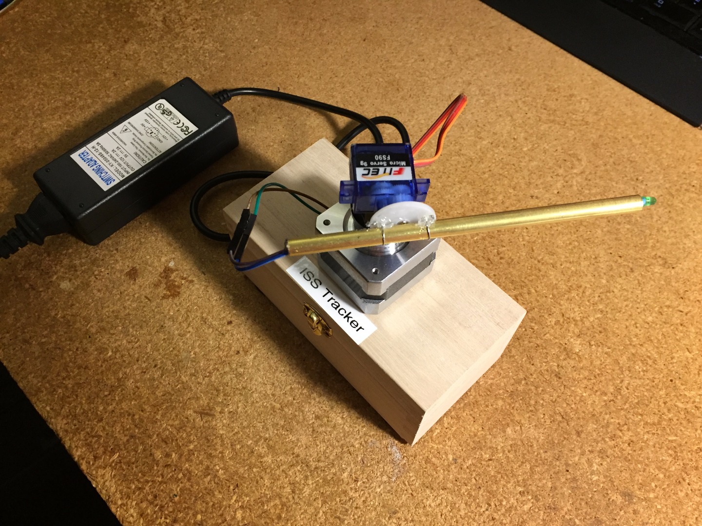
Expanding on my Stepper Motor controller using Adafruit Huzzah ESP8266 WiFi module by adding a small Servo, I created a mechanical device that can move in Azimuth (using a Stepper) and Altitude (using a Servo). This makes for a compact and low-cost remotely controlled celestial pointer. In this case, it can be used to point at the International Space Station (ISS) as it flies overhead.
Because the ESP8266 is a bit short on memory to handle the celestial calculations, I have split this project into two parts. The first part builds a generic Azimuth and Altitude control with an LED at the end of a pointer. It is controlled by sending HTTP commands to move the Stepper and Servo and light the LED.
A separate project will add a Linux server, such as a Raspberry Pi, to do the ISS calculations and send the HTTP commands to this ESP8299 pointer. Note that you could use this to point at any object using its horizontal and vertical positioning commands, not just the ISS.
Requirements
I used the following Adafruit components as they support the 12V and 3.3V requirements of the Stepper Motor and ESP8266 right out of the box. Otherwise, you would need to add regulators and related components to make the voltages compatible.
Hardware
- · Adafruit HUZZAH ESP8266 Breakout https://www.adafruit.com/products/2471
- · Adafruit TB6612 1.2A DC/Stepper Motor Driver Board https://www.adafruit.com/products/2448
- · Stepper motor NEMA-17 size 200 step, 12V 350mA https://www.adafruit.com/products/324 or equiv
- · Micro Servo, such as F92R or similar https://www.adafruit.com/products/169 or equiv
- · 12 VDC 1000mA power supply or better https://www.adafruit.com/products/798
- · 5 VDC 500mA power supply or better https://www.adafruit.com/products/501
- · FTDI or USB console cable https://www.adafruit.com/products/954 or equiv
- · A small LED and 220ohm resistor
- · 6 inch piece of brass or plastic tubing large enough diameter to fit the LED.
- · Knob or mounting gear to attach the servo to the stepper motor shaft.
- · Small (approx. 2.5” x 5” x 2.5”) box to put the electronics in and mount the Stepper on.
Michaels or Hobby Lobby have small inexpensive “keepsake” wooden boxes - · Breadboard, wire, etc.
Software
- · Arduino IDE with ESP8266 extension package installed (see Initial Setup below)
- · Download the ESP8266_ISSPointer web server app from GitHub
- · https://github.com/rgrokett/ESP8266_ISSPointer
Important Initial Setup of ESP8266
Before beginning the project, you should become familiar with the Adafruit HUZZAH board and programming it using the Arduino IDE. The best way is to use the excellent Adafruit tutorial:
https://learn.adafruit.com/adafruit-huzzah-esp8266-breakout/overview
You must be able to program your ESP8266 and connect wirelessly to it via browser.
Once completed, THEN continue below.
Software
First you should program and test the ESP8266 before adding its hardware wiring.
- STOP! Be sure you have already completed the initial software setup of the Arduino IDE and tested the ESP8266 with your WiFi network as described in the Initial Setup above!
- Ok, download the ESP8266_ISSPointer software from GitHub (https://github.com/rgrokett/ESP8266_ISSPointer/)
- Copy the AltAzPointer.ino program to your Arduino library area.
- Using Arduino IDE, edit the AltAzPointer.ino and insert your WiFi SSID and PASSWORD into the appropriate places.
- Compile and Upload the program using the FTDI or USB console cable just like shown in the Adafruit tutorial.
- When the program finishes loading, open a Serial Monitor, set to 115,200 baud, and press the ESP8266 RESET button to restart the program running.
- It should display the IP address once connected to your Wifi.
Also, the onboard Red LED should blink 4 times signifying it’s successfully connected.
- I used the built-in Arduino Stepper Library https://www.arduino.cc/en/Reference/Stepper to control the stepper motor and the Servo Library https://www.arduino.cc/en/Reference/Stepper for the Servo. These work fine with the ESP8266.
- Use a browser to go to http://{your_ip_addr}/stepper/start
This should respond back with “OK: MOTORS ON” in browser and the onboard LED blink once
Go to http://{your_ip_addr}/stepper/rpm?1 and see “OK: RPM = 1”
Go to http://{your_ip_addr}/stepper/steps?10 and see “OK: STEPS = 10”
Go to http://{your_ip_addr}/stepper/off and see “OK: MOTORS OFF”
NOTE: NO motors or servos need be attached for this to work!
- Unplug your ESP8266 and remove the FTDI/USB cable. It’s now programmed.
Wiring
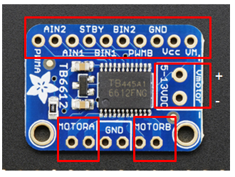
1. Connect up the Stepper Motor to the TB6612 Driver board:
- Hook one stepper motor coil to Motor A (red and yellow)
- Hook the second coil to Motor B (green and gray/brown).
TB6612 Driver
Device
MOTOR A
Stepper (red & yellow)
MOTOR B
Stepper (green & gray/brown)
VMotor V+
12V + power supply
VMotor GND
12V - Ground
Wiring
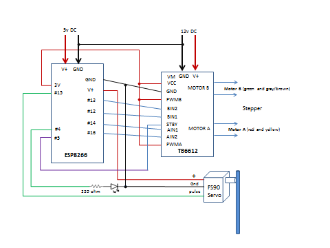
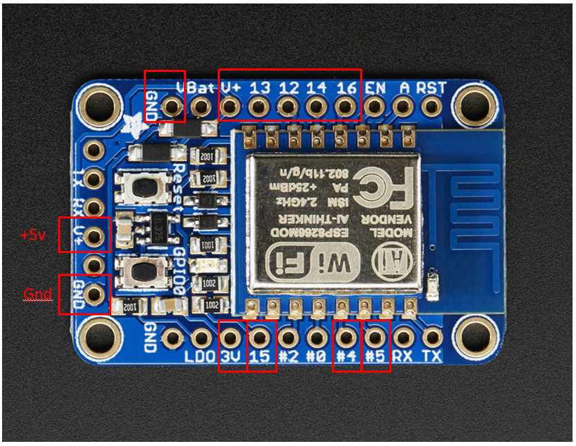
2. Next, wire up the Huzzah ESP8266 board to the TB6612 Driver board:
TB6612 Driver
HUZZAH ESP8266
Vcc
3V pin
GND
GND
AIN2
GPIO 16
AIN1
GPIO 14
BIN1
GPIO 12
BIN2
GPIO 13
PWMA and PWMB
Vcc
STBY
GPIO 5
3. Hook up the Micro Servo and LED. The Micro Servo runs on 3v pulses with low current, so should be fine to run directly off the ESP8266 lines. The LED must have a 220ohm or similar resistor soldered in series. It too, can run off the ESP8266 lines without extra support. (Assuming small LED!)
HUZZAH ESP8266
Device
GPIO 15
Servo (pulse)
GND
Servo (GND)
V+
Servo (V+)
GPIO 4
Resistor/LED combo + pin
GND
LED negative pin
Power
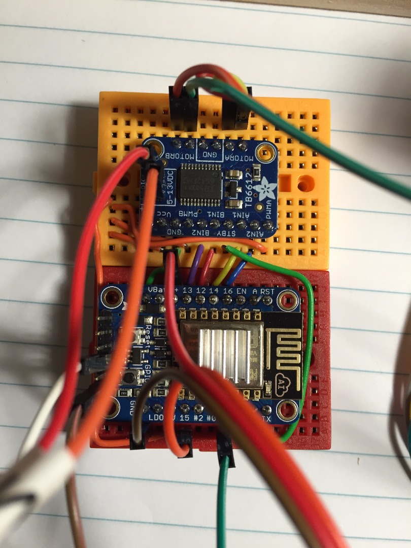
4. Connect the 12v DC power supply to V- (GND) and V+ pins on the side of the TB6612 Vmotor board. Connect the 5v DC power supply to the GND and V+ on the Huzzah ESP8266 board (the same connector that the FTDI/USB connector would go.)
You should power up the 5V first, or at the same time, as the 12v supply. I used an old laptop power supply that happened to provide both 5v and 12v. Otherwise, just plug them into a power strip and use its On/Off switch.
5. Double check your wiring, particularly power and grounds. Applying 5v or 12v to any pins on the ESP8266 other than V+ and GND will cause instant failure!
NOTE ON POWER:If your power supply in insufficient, you could cause the ESP8266 to reboot repeatedly or not be able to drive the Stepper Motor.
Even though the Huzzah ESP8266 can support a 12v supply, its regulator will get rather hot as it steps down the voltage for the ESP8266 module, thus I decided to use a separate 5v supply to the HUZZAH ESP8266 and a 12v power supply directly on the TB6612 Vmotor power leads. Be sure to leave the GNDs and 3v leads all in place.
Also, Steppers can get really hot w/o current limiting. Thus, be sure to send a “STOP” command (see below) to switch the TB6612 to standby which removes power from the Stepper. Use “START” command to reapply power.
You can tell the power has been removed from the Stepper, if you can easily turn the shaft (and the stepper is cool to touch.)
Initial Testing
Note that testing requires a Linux computer such as a
Raspberry Pi connected to your local network. This computer will be used for Part 2 of ISS Pointer at a later date.
Before completing the hardware construction, test the stepper, servo and LED using the test script “script/testmotors.sh”:
Turn on the power supply(s) and watch for the 4 blinks of the ESP8266 to show connected to your WiFi. If you don’t see them, verify power and wiring. If you need to debug, you can disconnect the 12v and 5v supplies and reconnect the FTDI/USB and plug in to PC and as shown in Software section above.
$ ping –c2 192.168.X.X
(your ESP’s IP)
You should see successful connection with 0% packet loss.
On the Linux computer, edit the testmotors.sh script with your ESP IP:
$ nano testmotors.sh <br># >> CHANGE FOR YOUR IP ADDRESS<br>ESP_IP="192.168.X.X"
Then try running it:
$ bash ./testmotors.sh
The LED should light and the stepper and servo should move. Again verify your connections to the motors and LED polarity if you have problems.
UNPLUG the power for the next part of the construction.
Building the Pointer
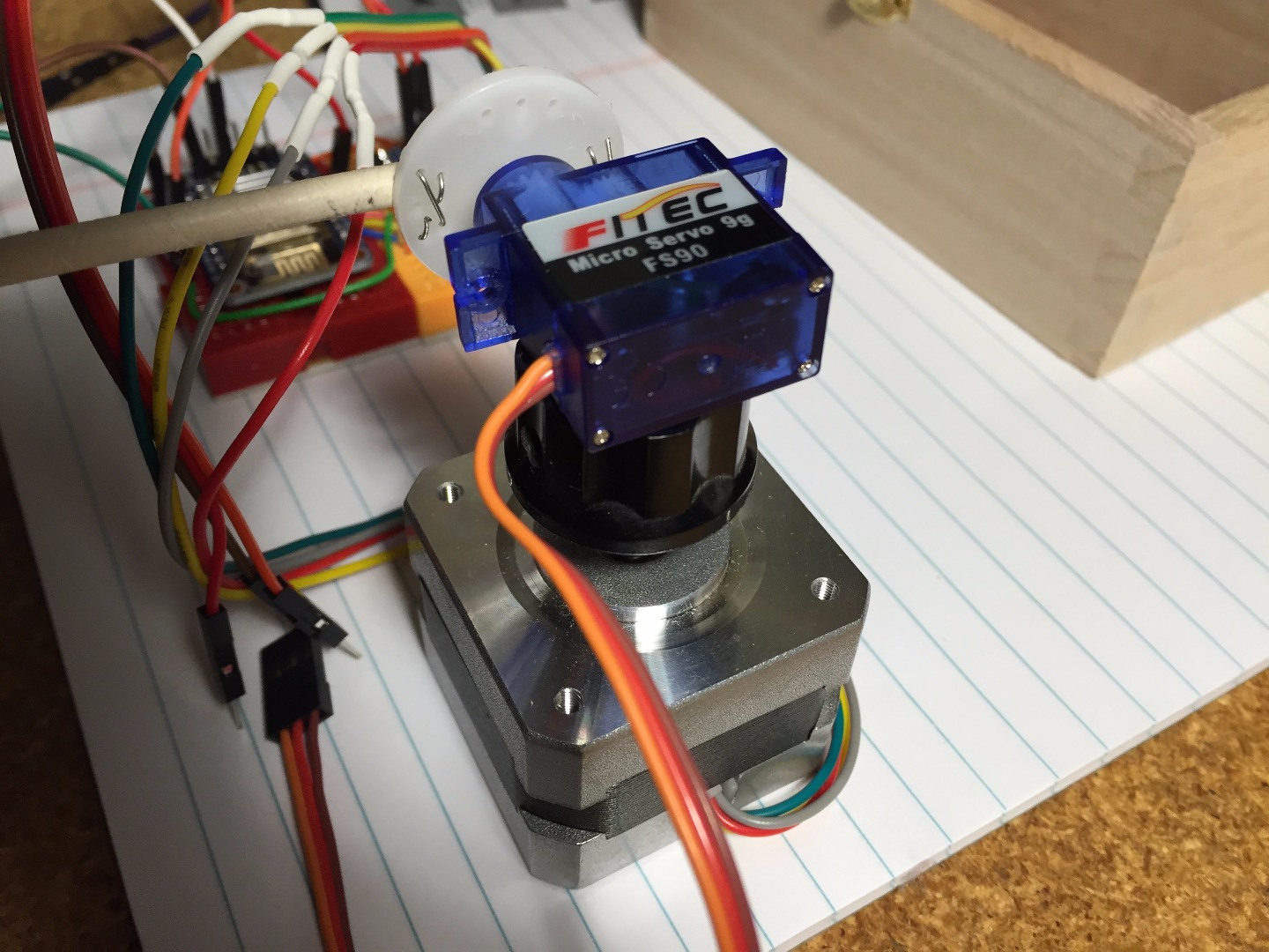
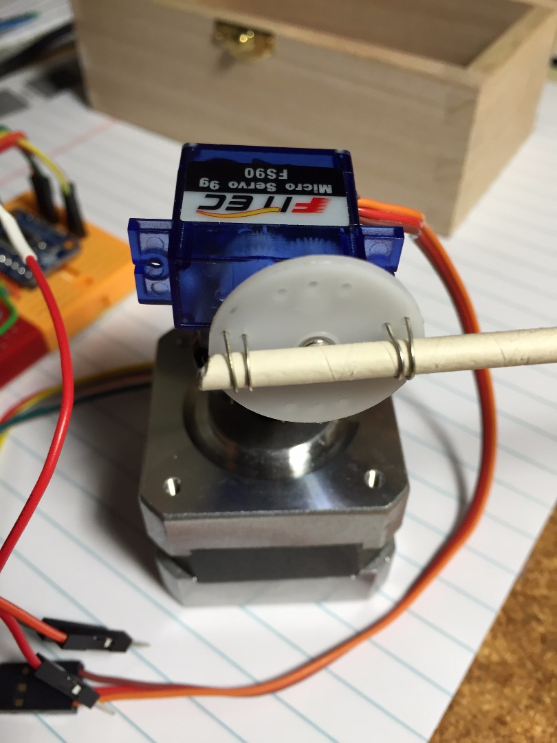
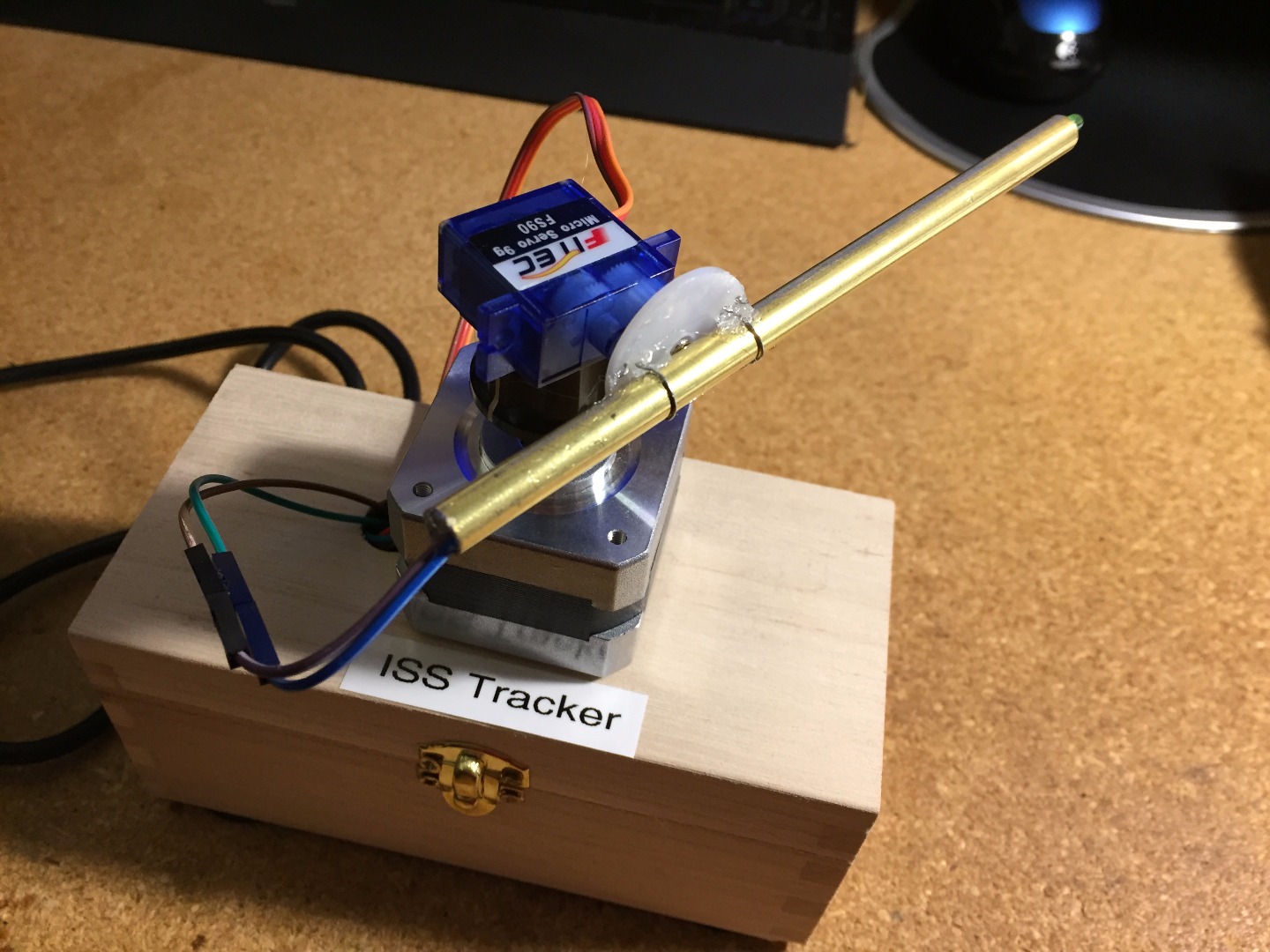
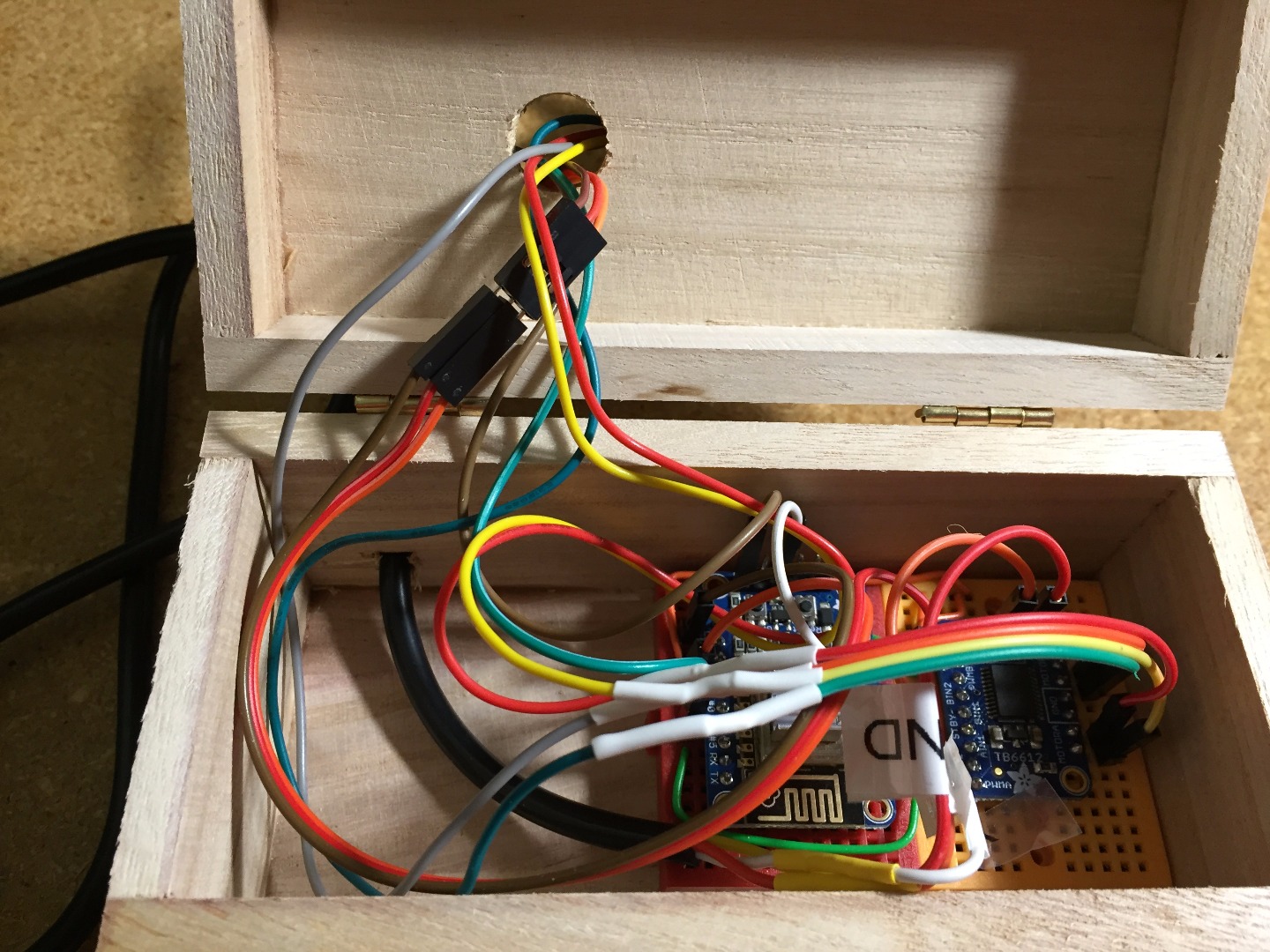
Next step will be to mount the Servo onto the Stepper motor shaft.
You need enough slack in the wires to the Servo and LED so that the Stepper can turn 0-359 degrees. Also, the Servo needs to be able to point from horizontal (0) to straight overhead (90) so that the pointer can point in any direction above the horizon.
Note that there are no limiter switches or zero positioning, so the ISS software in the second part of this project will have to make sure it never goes beyond 1 revolution of the Stepper or send anything other than 0 to 90 degrees on the Servo. The ISS software will also need to keep track of the 0 position of the Stepper so that it can return to its resting position.
- Using a gear or flat knob with set screw that will fit the Stepper motor shaft, mount the Servo on top. I just used hot melt glue to glue it on. Be sure that the direction of motion of the Servo is horizontal up to vertical overhead and not downwards!
- Mount the pointer (brass or plastic tube) onto the Servo. Be sure it defaults to Horizontal. But make sure it can point upwards. Again, I just used some wire and hot melt glue. This could be done prettier than what I did!
- Feed the LED thru the pointer tube to the front of the tube.
(Move the tube farther forward than shown in this photo, as the back could hit the Stepper when ISS is overhead!) ALTERNATELY, just mount the LED on top of the Servo, like a beacon! - I placed the electronics inside a small box with a hole drilled in to feed the wires out. I used double stick foam tape to mount the Stepper/Servo pointer to the top of the box.
- IMPORTANT: Using a compass, you need to turn the pointer to point North for your location. It doesn’t have to be perfect, just close. You should be able to easily turn the pointer. If not, the stepper motor may still be engaged.
The pointer should also be approximately horizontal. If the Servo is engaged, you may need to unplug the power and carefully adjust.
Final Testing
Note that testing requires a Linux computer such as a
Raspberry Pi connected to your local network. This computer will be used for Part 2 of ISS Pointer at a later date.
Again turn on the power supply(s) and watch for the 4 blinks of the ESP8266 to show connected to your WiFi. If you don’t see them, verify power and wiring. If you need to debug, you can disconnect the 12v and 5v supplies and reconnect the FTDI/USB and plug in to PC and as shown in Software section above.
$ ping –c2 192.168.X.X
(your ESP’s IP)
You should see successful connection with 0% packet loss.
On the Linux computer, edit the testpointer.py python script with your ESP IP:
$ nano testpointer.py
### USER EDIT<br>STEPIP = "http://192.168.X.X/" # REPLACE with your IP of ESP8266<br>STEPS  = 200   # REPLACE with your stepper number of steps per revolution<br>### END USER EDIT
Then try running it:
$ python testpointer.py
The LED should light and the stepper and servo should move, doing a speeded up example of a flyover. Again verify your connections to the motors and LED polarity if you have problems.
Once completed testing, feel free to experiment by creating scripts to send cURL commands to the ESP8266. Below is a list of HTTP commands available and a couple examples:
<p>$ curl http://192.168.X.X/led/on		# Turn on LED<br>$ curl http://192.168.X.X/stepper/start	# Move Stepper ½ turn and back
$ curl http://192.168.X.X/stepper/rpm?10
$ curl http://192.168.X.X/stepper/steps?100
$ curl http://192.168.X.X/stepper/steps?-100
$ curl http://192.168.X.X/stepper/stop
$ curl http://192.168.X.X/servo/value?45	# Move Servo to 45deg and back
$ curl http://192.168.X.X/servo/value?0
$ curl http://192.168.X.X/led/off		# Turn off LED</p>
Part 2 – ISSPointer Linux Controller
Overview
In Part 1, you created the Alt/Az Stepper/Servo pointer driven by an ESP8266. In Part 2, you add the Linux software needed to control the pointer based on the position of the International Space Station (ISS) as it flies overhead.
Requirements
- · Small Linux server, such as a Raspberry Pi, laptop running Linux, etc.
- · Network connection (wired or wireless) for the Linux server
- · Python version 2.7.x language
- · Python PyEphem (http://rhodesmill.org/pyephem/index.html)
- · Python program isspointer.py from GITHUB https://github.com/rgrokett/ESP8266_ISSPointer
- · Assumes basic knowledge of Linux command line shell commands
Linux Setup
This instruction is for Raspberry Pi, but feel free to set up your Linux server with any desired version of Linux OS as the Python program is available on all types of Linux.
This assumes you already have your Linux set up on your network and running.
1. Install Python 2.7 requirements, if needed:
$ sudo apt-get install python-pip python-dev
2. Install the excellent PyEphem software, which provides the astronomical calculations.
$ sudo pip install pyephem
3. Verify your Linux server can talk to your ESP8266: (replace with your ESP’s IP address)
<p>$ curl <a href="http://192.168.X.X/"> http://192.168.X.X/</a></p><p>Stepper usage:<br>http://{ip_address}/stepper/stop
http://{ip_address}/stepper/start
http://{ip_address}/stepper/rpm?[1 to 60]
http://{ip_address}/stepper/steps?[-200 to 200]</p><p>Servo usage:
http://{ip_address}/servo/value?[0 to 90]</p><p>LED usage:
http://{ip_address}/led/on
http://{ip_address}/led/off</p>
4. Get the isspointer.py program from GitHub and place in your home directory
https://github.com/rgrokett/ESP8266_ISSPointer
5. Edit the isspointer.py and update it with your Latitude, Longitude, approx. Elevation above sea level, and the IP Address of your ESP8266 Stepper Pointer (from Part 1).
$ nano isspointer.py

<p># YOUR LOCATION<br>LAT = 30.1      # Your Latitude (+N) degrees
LON = -81.8     # Your Longitude (+E) degrees
ELV = 11.0      # Elevation at your location (meters)</p><p># FOR ALT/AZ POINTER
STEPIP = "http://192.168.1.82/" # IP Address of YOUR ESP8266 AltAZ Pointer
STEPS  = 200    # Replace with your stepper (steps per one revolution)</p>
If your Stepper is different from the one listed in Part 1, then you may need to change the STEPS to match how many steps makes one revolution. Most are 200 steps per revolution.
6. Run the isspointer.py program to verify that all dependencies are good. You should get a display similar to below:
$ python isspointer.py
ISS PASS INFO
Seconds since last TLE check: 3600
['ISS (ZARYA)', '1 25544U 98067A   15365.91850903  .00005451  00000-0  86180-4 0  9997', '2 25544  51.6435 177.2551 0008253 348.0493 122.9026 15.55188097978806']
Current UTC time  : 2016/1/2 19:39:09
Current Local time: 2016-01-02 14:39:08.000005
Next Pass (Localtime): 2016-01-02 15:21:51.000005
UTC Rise Time   : 2016/1/2 20:21:51
UTC Max Alt Time: 2016/1/2 20:27:06
UTC Set Time    : 2016/1/2 20:32:19
Rise Azimuth: 308:01:05.1
Set Azimuth : 151:25:57.8
Max Altitude: 39:34:30.8
Duration    : 627

CURRENT LOCATION:
Latitude : -32:05:33.5
Longitude: 101:19:03.4
Azimuth  : 235
Altitude : -88
ISS below horizon ISS below horizon
7. If you get a Python error message, you may be missing dependencies or have a typo in your edits. You can search Google with the error message for more help.
8. Note that Raspberry Pi needs to be using NTP time in order to set its clock after reboots. Normally, this is part of Linux, but if your time does not match Current Local Time, then your Timezone may be incorrect.
Example:
$ date
Sat Jan  2 13:47:23 EST 2016
9. Note that PyEphem uses Universal Time (UTC), while the ISS Pointer needs your Local Time.
10. If you get good results, such as above, note several items:
Below shows when the next ISS pass will be.
Next Pass (Localtime): 2016-01-02 13:45:51
Rise Azimuth is the compass direction of the start of the next pass in Deg:Min:Sec. Max Altitude is the maximum angle above the horizon in Deg:Min:Sec. Duration is the number of seconds it takes the ISS to pass across your sky.
Rise Azimuth:333:59:02.6
Max Altitude:14:41:01.3
Duration    : 564
11. It also shows the current location of ISS and whether it is below the horizon or not.
12. Be sure your ESP8266 ISS Pointer is set to point North and Horizontal, as shown in Part 1. This is its resting position between passes. If not, it will not be able to point in the correct direction during a pass.
13. NOTE that the ISS Pointer is set to ONLY point on passes that rise more than 10 degrees above your horizon. That way only “true” overhead passes are pointed out, while the isspointer.py program shows EVERY pass that comes by you. So don’t be surprised if some passes do not move the pointer.
14. If you leave the isspointer.py program running, when a pass does come by above your 10 degree horizon, then you should see the ISS Pointer LED light and pointer move to point in its direction.
You can verify this by checking one of the ISS tracking web sites, such as http://iss.astroviewer.net/
15. After the pass is complete, the ISS Pointer should turn off the LED and return back to its resting position of North and Horizontal.
16. Once satisfied it is working properly, you can turn off the DEBUG and/or INFO messages as desired by editing the isspointer.py program
############ USER VARIABLES
DEBUG = 1       # 0 off 1 on
INFO  = 1       # Display ephemeris info
17. Last, you can make your isspointer.py run automatically after reboots by adding a small shell script and editing /etc/rc.local:
$ nano run.sh

#!/bin/bash
cd /home/pi
sudo rm nohup.out
sudo nohup python -u ./isspointer.py &
Append run.sh to bottom of /etc/rc.local:
$ sudo nano /etc/rc.local

/home/pi/run.sh
18. You can then look in nohup.out for the logging from the isspointer.py
$ sudo tail –f nohup.out
Feeling really industrious?
Next time, I will show adding SOUNDS to your passes and an LCD Display to your Raspberry.
Have Fun!
Part 3 – Adding Sound and LCD Display to ISSPointer
Overview
Here is an OPTIONAL feature that you can enhance your ISS Pointer with, if you are using a Raspberry Pi to control your ESP8266 AltAz Pointer stepper/servo. This is not required, but does make for a more interesting display.
In part 1 and part 2, Building an ISS Pointer Tracker you built the basic system.
https://www.instructables.com/id/Building-an-ISS-Pointer-Tracker-Using-Adafruit-HUZ/
In this part, you can add an LCD Display and audio alert sounds to your ISSPointer.
NOTE:
This assumes you are using a Raspberry Pi for the Linux Server, described in Part 2 above.
It also assumes you have it running the isspointer.py currently.Also this assumes the Raspberry Pi is being used “headless”, with no HDMI video GUI or keyboard/mouse. Instead, using SSH to access. Google headless raspberry pi or try this tutorial:
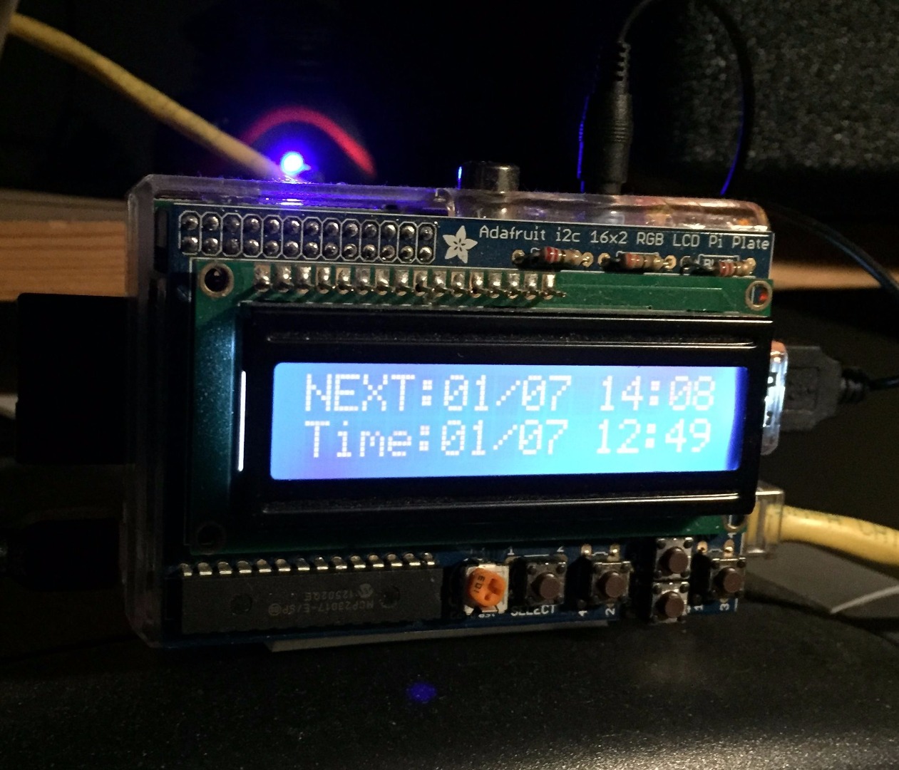
Once completed, your Raspi will display the next pass date/time, as well as alert you when a pass is occurring with audio sound effects.
Requirements
Besides the Raspberry Pi from Part 2 of this project, you will need:
- Adafruit LCD 16x2 Display for Raspberry Pi https://www.adafruit.com/product/1115
- External Audio amplifier/speaker (even a tiny laptop type speaker with USB power and Audio mini plug will work) Example: http://www.amazon.com/dp/B007OYAVLI/ref=psdc_6896...
- ISSPointer software with sounds "script/isspointer2.py" from Github: https://github.com/rgrokett/ESP8266_ISSPointer
Installation
You must build and install the Adafruit 16x2 LCD display onto your Raspberry Pi.
See the excellent instructions at Adafruit’s Learning site:
https://learn.adafruit.com/adafruit-16x2-character-lcd-plus-keypad-for-raspberry-pi
Once you have the display working, next is to add sound.
1. Plug in your mini speaker to the USB and audio jacks of the Raspberry Pi. Note that there isn’t a lot of power available from the USB, so powering other devices, such as mice and keyboards at the same time may not be possible.
2. Log into your Raspi using SSH and test the speaker using:
$ speaker-test -t sine -f 600 > /dev/null
3. You should hear sound. Press ctrl-C to stop it! If you don’t hear anything, test the speaker on an ipod, iphone, laptop, or any other device. If the speaker is ok, then may need to set the Raspi to send the audio out the audio jack instead of the HDMI:
$ sudo raspi-config
Choose Advanced Settings -> A6 Audio, then
select Force 3.5mm (headphone) jack and save/exit raspi-config.
In some instances, you may need to enable audio support:
$ sudo modprobe snd_bcm2835
And try the test again.
4. Download the ISSPointer software from GitHub https://github.com/rgrokett/ESP8266_ISSPointer
5. The Sound files should be placed in a /home/pi/sounds directory:
$ cd {dir_where_ISSPointer_files_are)
$ cp ./sounds /home/pi/
6. Test the sounds:
$ cd /home/pi/sounds
$ ls
$ aplay 2001function.wav
7. You should hear HAL 9000 talk to you.
8. Now the easy part (ha!), replace the original isspointer.py program with the new isspointer2.py:
$ cd {dir_where_ISSPointer_files_are)
$ cd ./script
$ mv isspointer2.py /home/pi/isspointer.py
9. Edit the isspointer.py and update it with your Latitude, Longitude, approx. Elevation above sea level, and the IP Address of your ESP8266 Stepper Pointer (from Part 1).
$ nano /home/pi/isspointer.py
# YOUR LOCATION
LAT = 30.1      # Your Latitude (+N) degrees
LON = -81.8     # Your Longitude (+E) degrees
ELV = 11.0      # Elevation at your location (meters)
STEPIP = "http://192.168.X.X/" # IP Address of YOUR ESP8266 AltAZ Pointer
STEPS  = 200    # Replace with your stepper (steps per one revolution)
10. You can control the Audio (turn it off/on) via the “AUDIO = 0 or 1” switch.
11. Also you can turn off the sound and display at night using the control:
QUIET = [ 00, 07 ] # Don't play audio between midnight & 7:59AM
12. If you originally set up your ISSPointer isspointer.py to auto-start on reboot by adding it to /etc/rc.local, then just reboot your Raspi. When it comes up, you should hear the HAL sound again as well as see the display flash a message.
$ sudo reboot
13. If something goes wrong, look in the nohup.out file for error messages. Most likely, a missing dependency!
$ sudo cat /home/pi/nohup.out
Possibly, the Adafruit LCD libraries are not in your path. You may need to copy them from the Adafruit_Python_CharLCD subdirectory as shown in their tutorial listed above. These are:
Adafruit_CharLCDPlate.pyc
Adafruit_I2C.pyc
Just place in your /home/pi directory with the isspointer.py program.
14. You can place the Raspi in any convenient location to see the LCD display. Since the ESP8266 AltAz Pointer is wireless, it can be placed separate from the Raspi, or they can be close together.
Remember, your Pointer will not work unless Raspi is running the isspointer.py program. But, you can use the Raspi for other things, if desired. Just remember to leave it running to track ISS.
With attention to details and a little bit of luck, you should now have an elaborate self-contained ISS Tracking/Pointing system.
Have Fun!