Building Habitats and Infrastructure in Canada's Arctic
by boysenberry in Design > Digital Graphics
425 Views, 3 Favorites, 0 Comments
Building Habitats and Infrastructure in Canada's Arctic
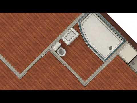
Hi everyone, my name is Daniel and I'm a grade 12 student. In this Instructable, I'll be going through my design process for creating a habitat and infrastructure intended for Iqaluit, the capital city of Nunavut Territory, located in Canada's Arctic. All design and animation was done entirely in Fusion360, and all the other tools/resources are free to use. I'll be highlighting some of the less known features of Fusion360, like scripting, motion studies, t-spline modelling, and appearances. If you have any questions or comments, feel free to leave them below. The video introduces my project and some of the cool parts of my design. Hope you enjoy!
Supplies
You'll need Fusion360 for this project. If you don't already have an free student account, go to the Autodesk education website and click get started under Fusion360. It's a great software that combines design, simulation, rendering, and animation into one app. You can also run it in your browser if your computer isn't very good. Many of Fusion360's basic features are intuitive to learn and there are many tutorials available online, so I'll be highlighting some of the features that are less known.
Other tools/resources I used:
Recording: OBS Studio
Video Editing & SFX: Microsoft ClipChamp
Music: Kevin MacLeod, Vexento
Graphing/Mathematical Diagrams: Desmos, GeoGebra
Mathematical Equations: Overleaf
Image in Motion Study by Adam Chang: https://unsplash.com/photos/snow-field-and-green-pine-trees-during-daytime-IWenq-4JHqo
Image in Motion Study by Gabriel Alenius: https://unsplash.com/photos/aerial-photo-of-snow-covered-tree-lot-USXfF_ONUGo
Inspiration for BBQ Grill: https://www.ikea.com/ca/en/p/grillskaer-gas-barbecue-w-side-table-stainless-steel-outdoor-s79504620/
Inspiration for Excavator: https://www.topmarkfunding.com/what-is-an-excavator/
Permafrost/Snow Texture: https://polyhaven.com/a/snow_02 by Rob Tuytel
HDRI: https://polyhaven.com/a/birchwood by Sergej Majboroda
I've done my best to include all the tools/resources I used, but if you're not sure what tool/resource I used for something, feel free to ask!
The Arctic Zone
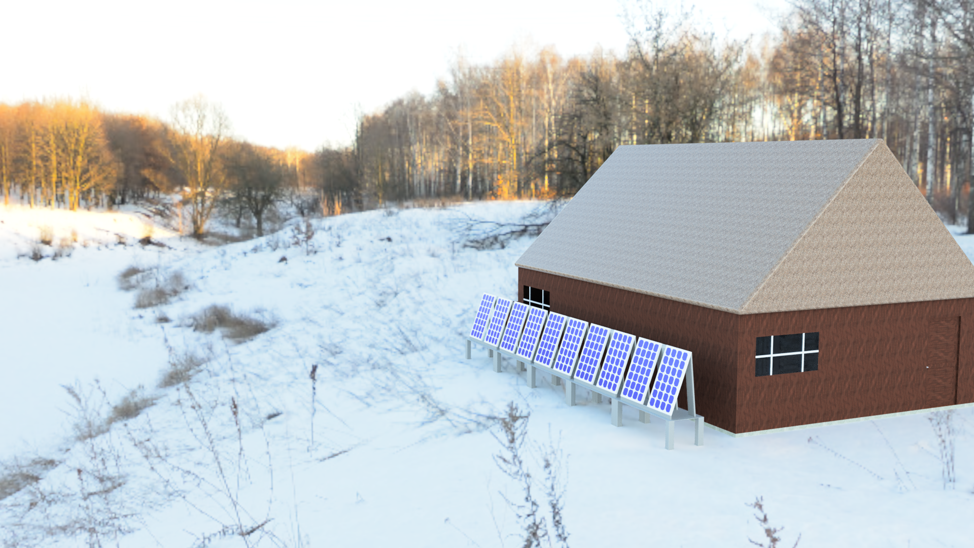
I became interested in the Canadian Arctic after reading a Toronto Star article about the effects of disappearing permafrost in Canada's north. Here's an excerpt that really stood out to me:
"In Nunavut, water and sewer pipes in the capital Iqaluit are cracking during the winter as the ground shifts – costing the city hundreds of thousands of dollars in repairs. In Nunavik, the northern third of Quebec, ponds and lakes are 'browning' as thawing permafrost deposits organic matter into the water. In the west, cracks large enough to swallow a man have opened on the Alaska Highway in the Yukon (Wallace, 2019)."
Besides causing damage to public infrastructure, the melting permafrost also puts the homes of residents at risk. In Iqaluit, many residents have homes built on steel pipes that run deep into the permafrost, but the pipes are now being shifted by the melting permafrost (Wallace, 2019).
Based on these reports of infrastructure damage, I've brainstormed and designed a home intended for the harsh weather conditions of Iqaluit, Canada.
Source: https://projects.thestar.com/climate-change-canada/nunavut/
The Foundation of the Habitat
To start off, the biggest problem to address is the lack of a stable foundation for the house. The method of running steel pipes deep into permafrost described in Step 1 simply isn't viable as permafrost melts.
There are 4 ways the Alaska Department of Transportation and Public Facilities builds infrastructure on permafrost:
"Here at Alaska DOT&PF, we have four main strategies to manage the effects of permafrost thaw on our infrastructure:
- Avoid it. If we can, we try to avoid building on permafrost, although that’s not always possible.
- Remove it. If possible, we will dig out the frozen material under the ground and replace it with stable material.
- Keep it frozen. We have a variety of techniques to keep the ground frozen, and are always experimenting to find new and better methods.
- Accept it. The challenges with the other three options leave us with our last strategy: build over permafrost using traditional construction methods and accept the consequences."
Option 2, removing the permafrost, isn't practical for large areas of land like a highway. This method is expensive and is a major logistical challenge (Alaska, DOT, n.d.). However, a house occupies a much smaller piece of land and it could be a feasible option here. When the permafrost is removed, it is replaced with gravel (Alaska DOT, n.d.).
A June 2010 report from the Transportation Association of Canada states that heavy equipment for excavation should only be used when the ground is frozen to prevent damage to the ground (TAC, 2010). Therefore, the excavation should occur during the winter, after which the concrete foundation of the house can be poured and built upon.
Sources:
https://dot.alaska.gov/traveltopics/building-in-permafrost.shtml
https://tac-atc.ca/sites/tac-atc.ca/files/site/doc/resources/primer-permafrost2010.pdf
Home Design
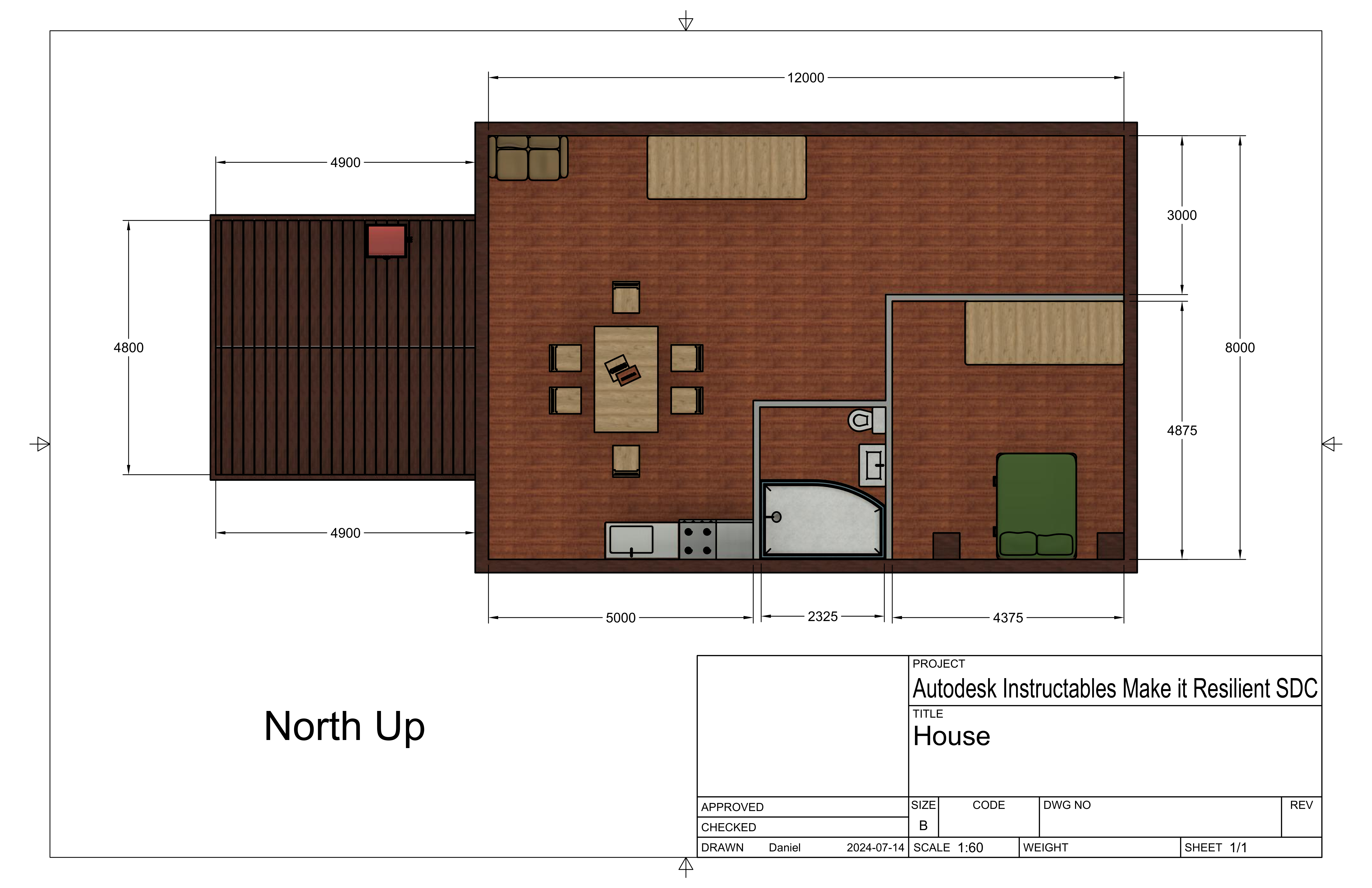
The home I designed can be described as a starter home, with one bedroom, one washroom, and 96 square metres of interior floor space. Darker shades of wood can be seen on the exterior, while the lighter shades of wood on the inside are complemented with brown and dark green accents. The bedroom door is placed far within the home to prioritize privacy, and next to the washroom door for convenience. Besides those two rooms, there are no other interior walls, as I've tried to created an open, spacious, environment.
One window on the south side and two on the north side let in sunlight during the day, and the six chairs around the dining room offer the inhabitants a variety of places to work or eat depending on their preferences. The bedroom windows on the east side of the house let sunlight in each morning, making waking up a more pleasant experience. I designed the deck to face west to catch the setting sun each evening. It has a usable space of 4.8 m by 4.9 m, enough to entertain guests and host a BBQ grill.
Conserving Energy - the Curtains
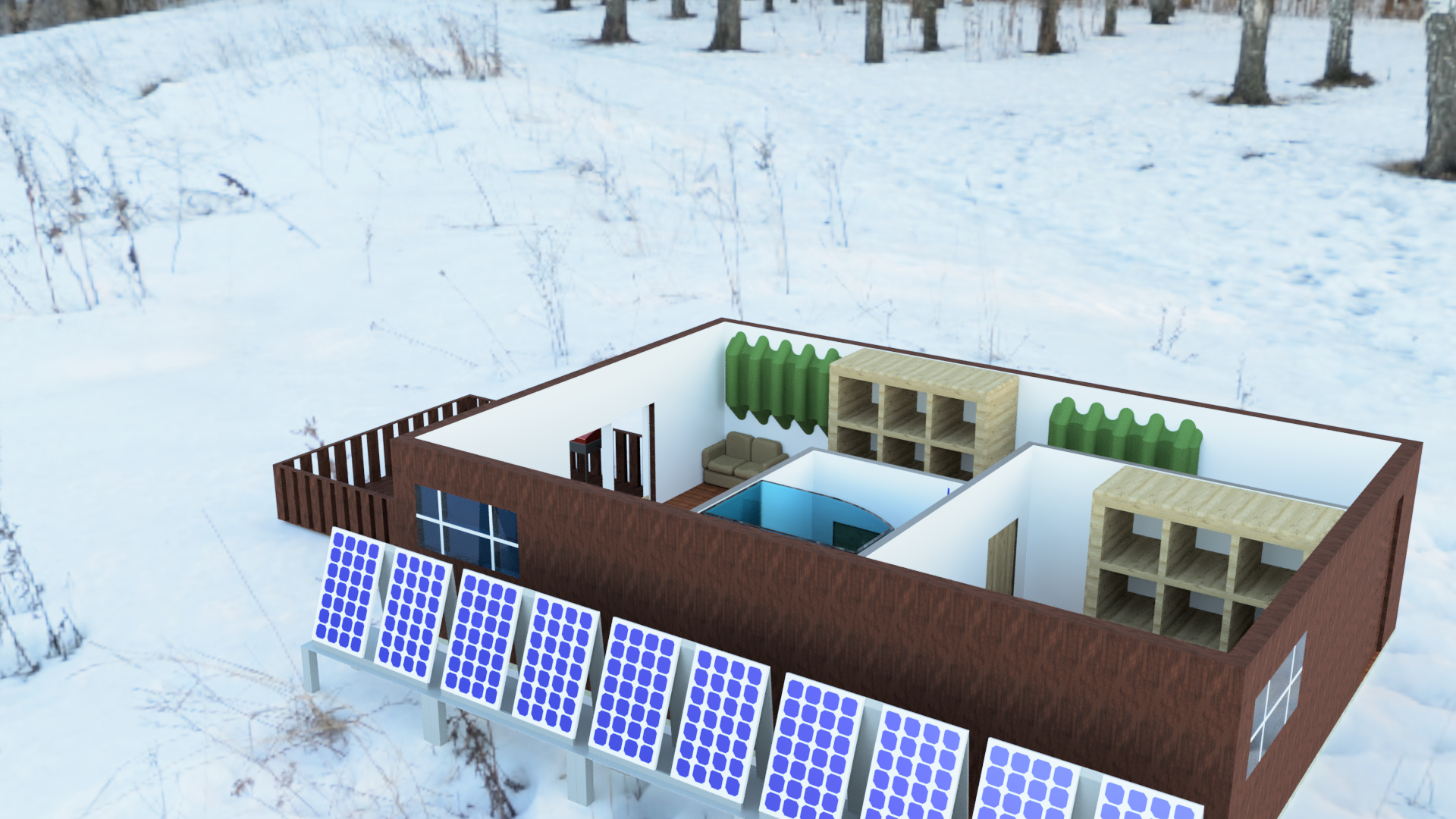
As you might've noticed in the introduction video, I designed special curtains that cover the windows entirely. According to the US Department of Energy, somewhere in the range of 30% of heating energy is lost through windows (DoE, n.d.). Closing ordinary curtains reduces the amount of heat lost by 10% (DoE, n.d.), and I've designed these curtains to wrap around the windows entirely to reduce the heat loss even further. Just like the windows, the curtains are modular, and can be used on windows that aren't receiving sunlight to conserve as much heat as possible.
Source:
https://www.energy.gov/energysaver/energy-efficient-window-coverings
Energy Self-Sufficiency
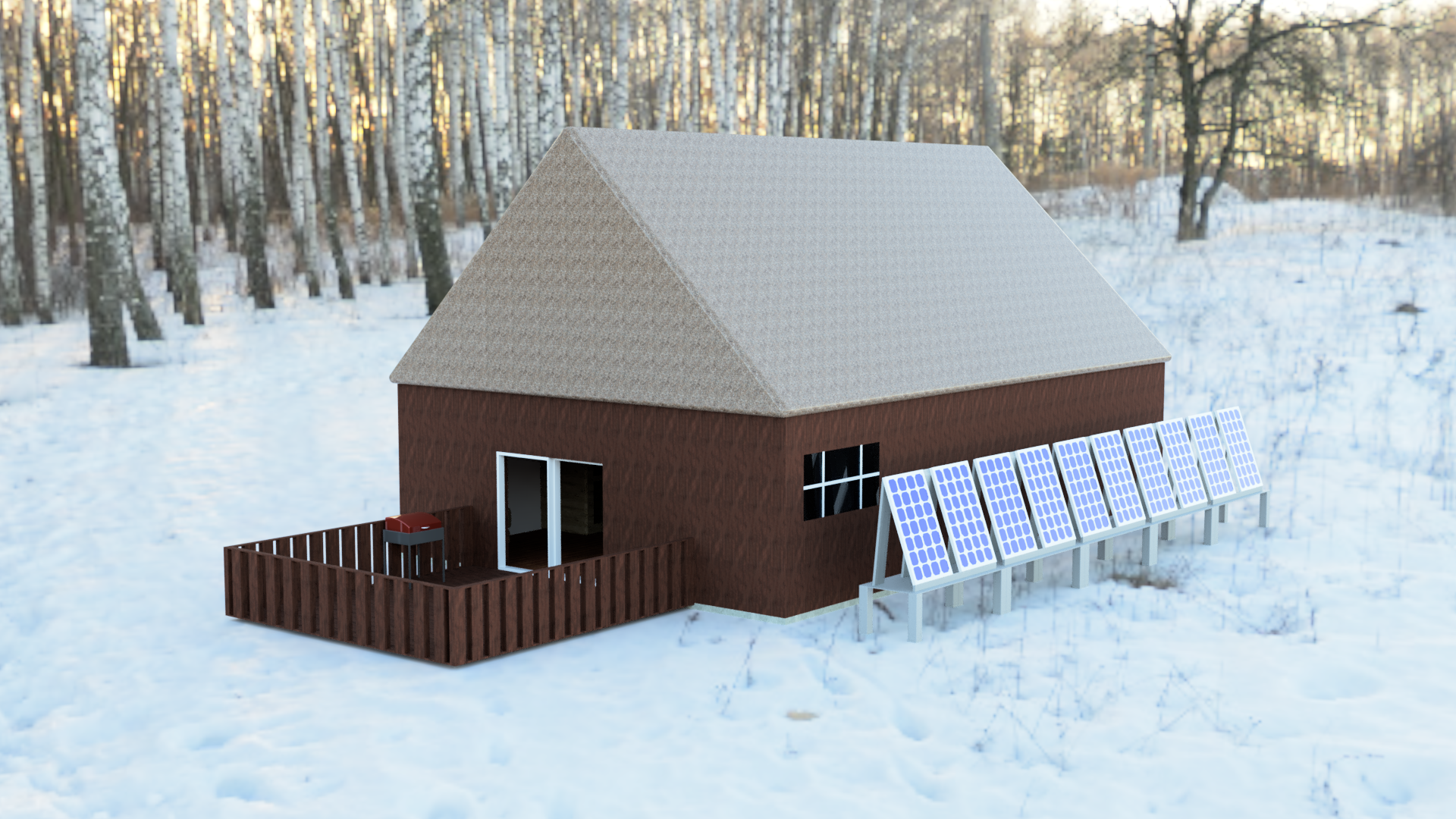
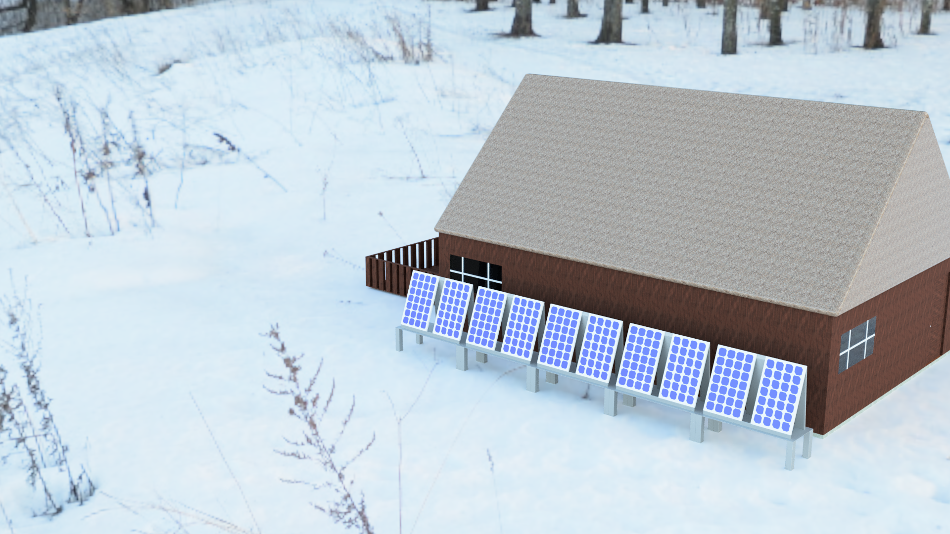
In northern Canada, utilities can't always be relied upon. The Toronto Star article discussed in Step 1 details an instance where residents were left without running water for days until a pipe could be repaired (Wallace, 2019). A similar situation might occur with power lines, and so it's a good idea to try to incorporate some energy self-sufficiency into a home design. Some residents of Iqaluit have already installed solar panels, and there's also grant provided by the Nunavut Housing Corporation to defray costs (McKay, 2022). I briefly considered a gas or diesel generator, but reliance on gas or diesel isn't ideal in a remote setting. Besides, the city of Iqaluit already burns somewhere in the range of 16 million litres of diesel per year (McKay, 2022).
To figure out the optimal angle for the solar panels, I referred to a Stanford research paper by Jacobson and Jadhav. They give the optimal angle as a function of ϕ, latitude.
Optimal Angle = 1.3793+ ϕ(1.2011+ ϕ(-0.014404+ϕ0.000080509))
The latitude of Iqaluit according to Google Maps is 63.746881974526396 degrees. Substituting the latitude in, the optimal angle is approximately 19.942 degrees from the vertical. This is why the panels in the article seem to be mounted vertically. The couple interviewed in the article on solar panels in Iqaluit installed 10 solar panels to completely meet their energy needs (McKay, 2022), and this seemed like a good place to start. I've opted for panels placed on racks on the ground, for ease of maintenance. Brushing the snow off the panels in the winter is also easier if they're on the ground, and the custom racks I designed allow the panels to sit at an optimal 19.942 degrees from the vertical to capture the maximum amount of energy possible.
Sources:
https://projects.thestar.com/climate-change-canada/nunavut/
https://www.cbc.ca/news/canada/north/solar-panels-homes-nunavut-1.6592317
https://web.stanford.edu/group/efmh/jacobson/Articles/I/TiltAngles.pdf
https://www.forbes.com/home-improvement/home/how-many-watts-run-house/
https://www.homedepot.com/c/ab/light-bulb-brightness/9ba683603be9fa5395fab9014959566a
Rainwater/snow Collection
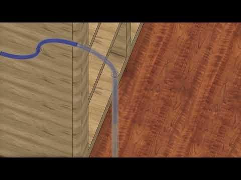
Besides energy self-sufficiency, it's also a good idea to ensure water self-sufficiency due to Iqaluit's remote location. The rainwater/snow collection system is currently connected to the toilet, but in an emergency, water can be collected from the storage container and filtered for drinking and cooking. It can also be shared with neighbours and friends who don't have access to running water.
Animating the water moving was a really cool process - I had to get a bit more creative since Fusion360 isn't really designed for this kind of animation. Let me know what you think!
Animating the Car With Motion Studies
I animated the car moving along the road in the beginning by using a motion study. Start by coming up with a path for your car to follow. I decided to define the path of the car by the function f(x) = ln(x+1) {0 ≤ x ≤ 5}. Here's a link to the graph if you'd like to take a closer look: https://www.desmos.com/calculator/c3rnlyb2ow.
The reason I'm defining the path with a known function is so I can change the angle of the car accurately as it moves along the path. If you use a random path, you'll have to guess the angle the car later on.
Highway Construction Considerations
In such an extreme environment, building a road is no easy task. Remember the 4 ways Alaska DOT&PF build over permafrost? Here, removing the permafrost isn't feasible since a road would cover vast swaths of land. However, insulation foam can be placed under the road surface to keep permafrost frozen (Alaska DOT, n.d.). This has been tried and tested, and would be a good option to minimize the effect of melting permafrost as the climate changes for the worse. Here's a video showing what the process might look like.
The Code/creating the Road
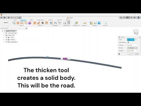
Importing the graph into Fusion360's sketch environment is a bit of a challenge. Fusion360 doesn't natively have the ability to sketch curves from functions, but it can be done with a script. If you don't already have Microsoft's Visual Studio Code, go ahead and download it.
Navigate over to the Utilities tab at the top of the Fusion360 toolbar, and click Scripts and Add-Ins (Shift+S). Create a new script in Python, and you'll be redirected to VSCode.
I adapted this code from https://capolight.wordpress.com/2018/07/02/how-to-sketch-equation-curves-in-fusion-360/. The author has a great example that helped me understand how this works. The important parts are startRange, endRange, xCoord, and yCoord. startRange and endRange define the x-values where your function starts and ends. The script creates sketch points at equally spaced x-values t, so for most cases the xCoord is simply t. The yCoord is where you define your function in terms of t. This could be anything from a cubic function to a square root function, or any combination of functions.
# This code was adapted from https://capolight.wordpress.com/2018/07/02/how-to-sketch-equation-curves-in-fusion-360/.
import adsk.core, adsk.fusion, adsk.cam, traceback, math


def run(context):
  ui = None
  try:
    app = adsk.core.Application.get()
    ui = app.userInterface
    design = app.activeProduct
    # Get the root component of the active design.
    rootComp = design.rootComponent
    # Create a new sketch on the xy plane.
    sketches = rootComp.sketches
    xyPlane = rootComp.xYConstructionPlane
    sketch = sketches.add(xyPlane)
    points = adsk.core.ObjectCollection.create() # Create an object collection for the points.


    # Enter variables here.
    startRange = 0 # Start of range to be evaluated.
    endRange = 5 # End of range to be evaluated.
    splinePoints = 50 # Number of points that splines are generated. Using more than a few hundred points may cause your system to lag.
    i = 0


    while i <= splinePoints:
      t = startRange + ((endRange - startRange)/splinePoints)*i
      xCoord = (t)
      yCoord = (math.log(t+1)) # This is where you can change the function. For example, you could try putting t*t for a quadratic function.


      points.add(adsk.core.Point3D.create(xCoord,yCoord))
      i = i + 1


    #Generates the spline curve
    sketch.sketchCurves.sketchFittedSplines.add(points)


  # Error handling
  except:
    if ui:
      ui.messageBox('Failed:\n{}'.format(traceback.format_exc()))
As you can see the function is f(x) = ln(x+1), and its domain is {0 ≤ x ≤ 5}. Dimensions are specified in the code in centimeters, so the domain is {0 ≤ x ≤ 50} in mm.
Time to run the script! Head back over to the Utilities tab, click Scripts and Add-Ins (Shift+S), and double click the script you'd like to run. I've also shown how I created the road.
Creating the Car
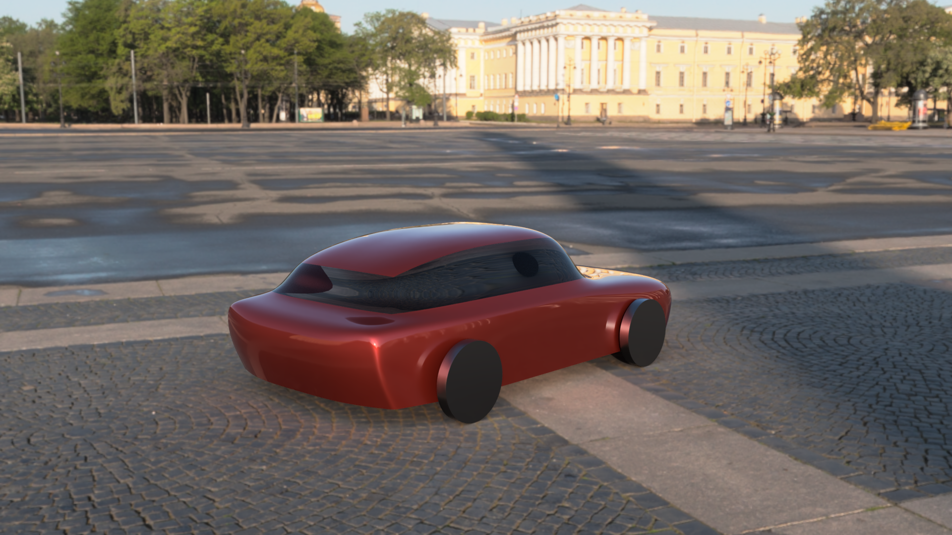
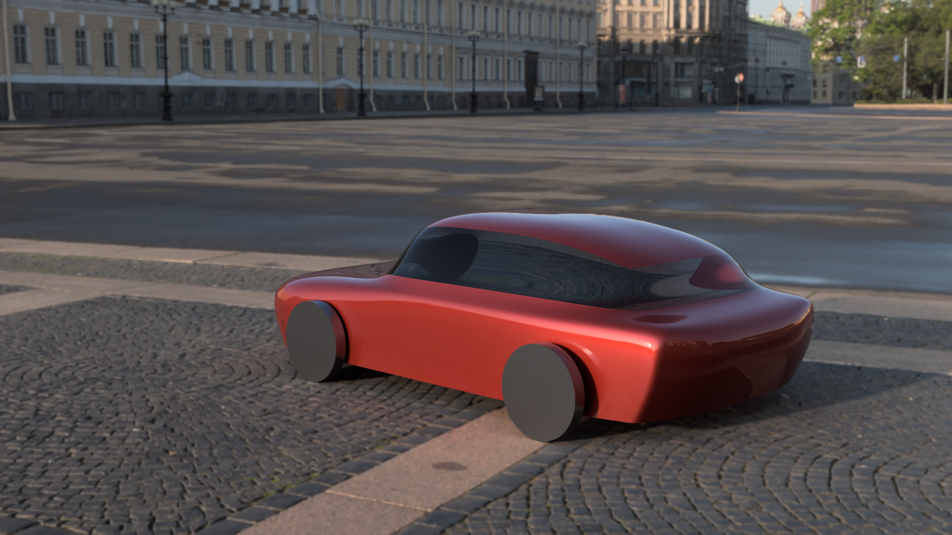
I followed this tutorial from Max 3D Design: https://www.youtube.com/watch?v=wyqQtLjt_WM. I went for a less sporty car shape, but as you can see, there is a lot of flexibility in the design process. You could try modelling a truck, for example, based on the same workflow.
Angle Calculations for the Car
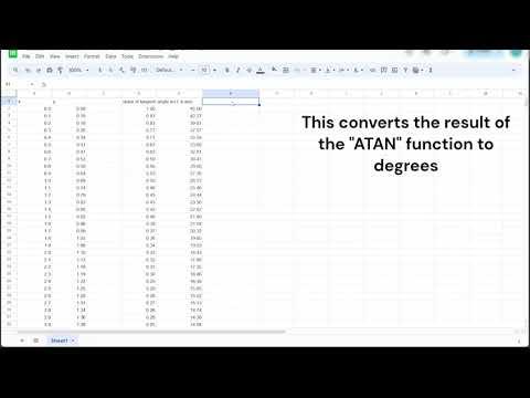
For the motion study, we need to tell Fusion where the car is at several points in time - that's why the script created 50 points. The more points there are, the smoother the animation will look. Here's an overview of the Google Sheet I created to calculate the car's angle at each of the 50 points. It's a really cool application of calculus.
Motion Study
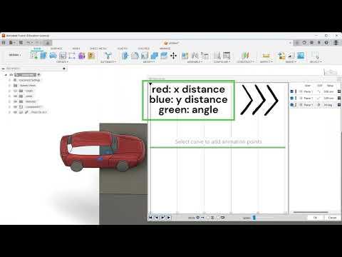
In this video, I demonstrate how to create the planar joint between the car and the road, and the motion study.
The background image was inserted into Fusion360 with the Canvas command and is used under the Unsplash license.
Image by Gabriel Alenius: https://unsplash.com/photos/aerial-photo-of-snow-covered-tree-lot-USXfF_ONUGo
Creating the Hand in the Touchpad Intro
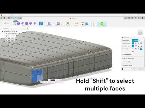
Remember the touchpad animation at the beginning of the video? I designed the hand using the Create Form modelling environment in Fusion360. Here's a quick video demonstrating how I did it. I've also attached the Fusion360 file if you'd like to take a look.
Modifying the Hand's Appearance
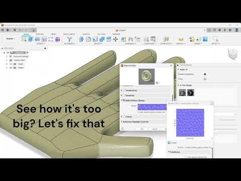
To make the hand more realistic, I added an appearance to it and adjusted the scale, and colour. Here's a video demonstrating how to do it.
Thanks for Reading!
I hope you've learned something from my Instructable! My favourite part of this design was learning how to use the motion study, but I've enjoyed the combination of engineering, CAD, and interior design that this project has woven together. Perhaps a home in Arctic Canada doesn't have to look so different from what we're used to, but with a few tweaks it can be much better suited to such an extreme environment.
Here's a few more tips/things I learned during this project:
- When importing an HDRI, you may need to uncheck the Flatten Ground option in the render settings. Before I unchecked it, my renderings came out distorted.
- Try to fully restrict all sketches. This makes changing things later so much simpler. If you're creating abstract or more artistic geometry, this might not be always possible.
- Place sketch points to quickly move objects into position in an assembly. I demonstrate this at the beginning of the video in Step 12.
- Use selection filters to quickly select lots of edges/faces/vertices. This becomes useful if you need to fillet or chamfer a bunch of edges or faces.
- Set up keyboard shortcuts. When I had to split a lot of bodies, I assigned the D on my keyboard as a shortcut to the Split Body command, and it saved me a lot of time.