Build an Automatic Watering Reservoir With WiFi Alerts for Cultivation Setups
by fedwester in Circuits > Gadgets
1053 Views, 5 Favorites, 0 Comments
Build an Automatic Watering Reservoir With WiFi Alerts for Cultivation Setups
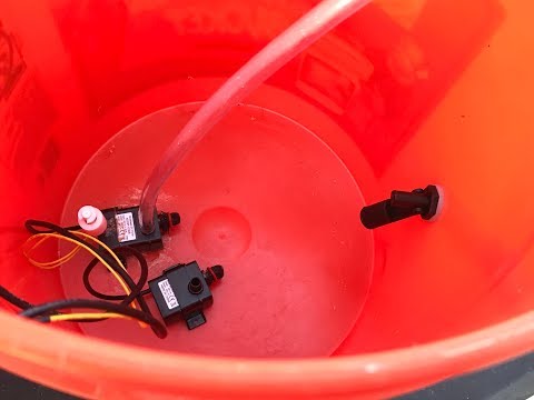
In this DIY tutorial project we will show you how to build an automatic watering reservoir with WiFi alerts for a cultivation setup or for an automatic watering system for your animals such as dogs, cats, chickens, etc.
Supplies
- five gallon bucket
- 3M 90 adhesive glue spray
- 1/4" inner diameter tubing (clear or dark tubing)
- sandpaper
Adosia's Automatic Plant Feeder Reservoir Subassembly Kit:
- 1× Adosia IoT device
- 1× 12V water pump / level switch assembly (detect empty water / protect pumps)
- 1× extra 12V submersible water pump for dual pump operation
- 1× ruggedized analog soil moisture sensor
- 1× horizontal water level switch (detect low water level)
- 1× DC power supply (12V/1A)
Prepping the Five Gallon Bucket
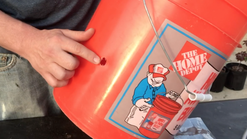
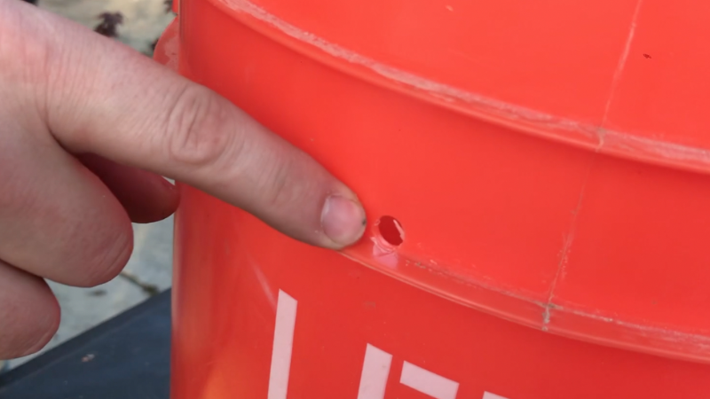
The first thing you want to do is drill three holes in the bucket.
One hole should be 1/2" in diameter and located at least 6" from the bottom of the reservoir. This hole will be used to mount the horizontal water level sensor switch, and should be placed above where the bottom vertical water level sensor switch resting on the pump is poisoned. The horizontal level switch will be used to warn us when the water level is getting low. The vertical water level switch residing on the pump protects the pump by preventing any further pumping when triggered, effectively representing the system being out of water entirely.
The second hole will be 3/8" in diameter placed near the top of the reservoir. This is for the 3/8" outer diameter tubing (connected to the pump outtake) to exit the reservoir when a bucket lid is present.
The third and final hole should be 1/4" to 3/8", and will be used to transport the pump and vertical level switch electrical wires to the outside of the reservoir.
BEFORE YOU DRILL: Figure out where on your bucket you will mount your WiFi board. Lay out your components and make sure each of the 3 wire snap connectors for the pump/level switches can reach the connecters on the board based on where everything is positioned.
Connecting the Water Level Sensor Switch and Pump
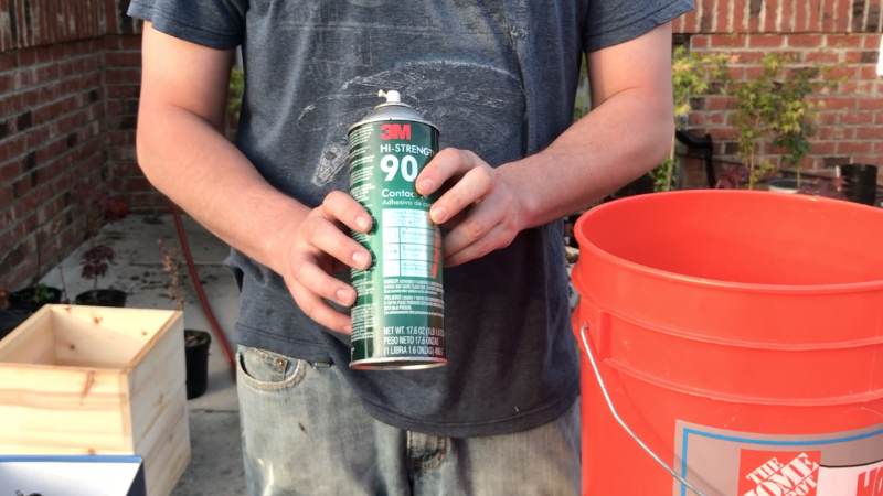
To connect the vertical water level sensor switch/pump assembly to the bottom of the bucket you will need an adhesive glue spray. We like to use this 3M 90 high strength contact adhesive spray. It works the best and was the only thing we could find recommended for bonding polypropylene plastics together.
Scuffing the Bucket and the Water Level Sensor Switch
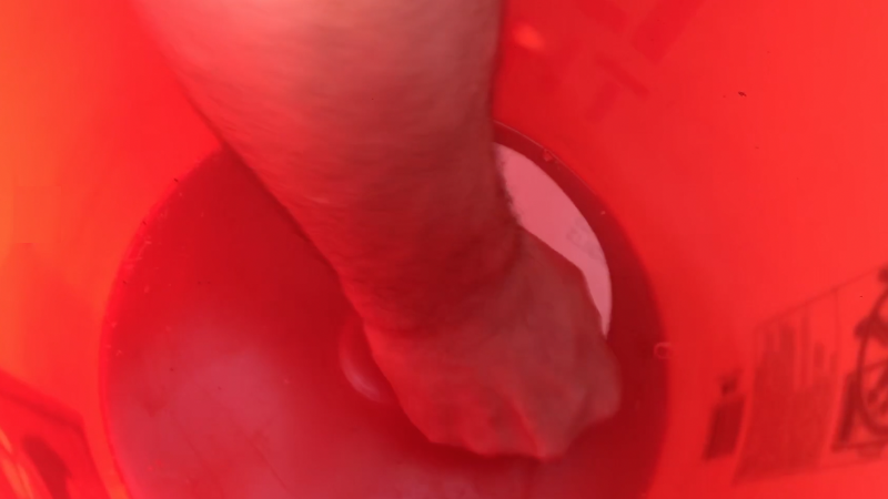
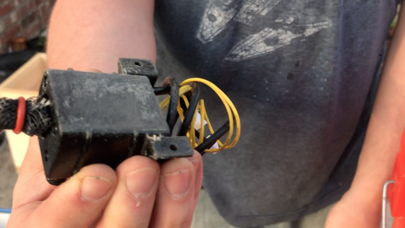
Before spraying the adhesive glue you should scuff the bottom of the five gallon bucket and the bottom of the pump assembly with sandpaper. This will help bond the bucket and sensor switch a lot better.
Using the 3M 90 Glue Spray
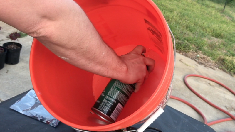
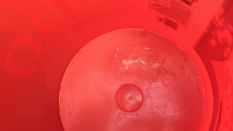
After scuffing the bottom of the bucket, spray the area with the 3M 90 spray and wait about 45 seconds. The area will start to bubble once sprayed, which is normal, it means the glue is working.
Spraying the Water Level Sensor Switch
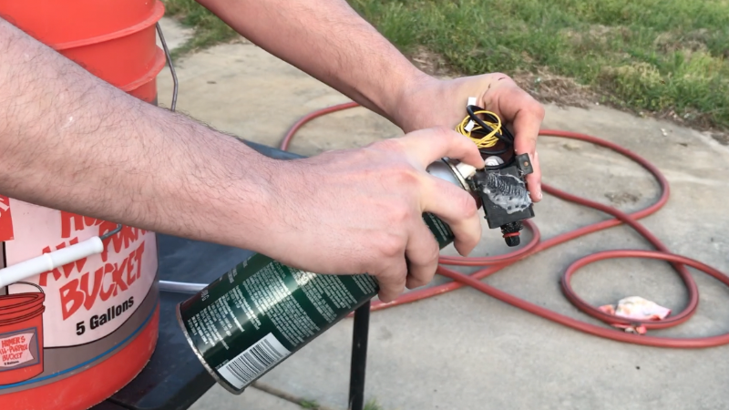
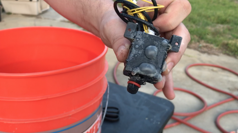
While waiting for the glue in the bucket, spray the water level switch / pump assembly with the 3M 90 glue contact adhesive as well.
Attaching the Hose to the Pump/sensor Switch
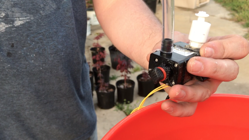
Before attaching the water level sensor switch to the bottom of the bucket, we first attach the 3/8" outer diameter tubing to the pump outtake. We attach this tube before bonding the pump down as it helps avoid dislodging the pump when attaching it later after the pump has already been glued down to the reservoir basin.
Attaching the Pump/sensor Switch to the Bucket
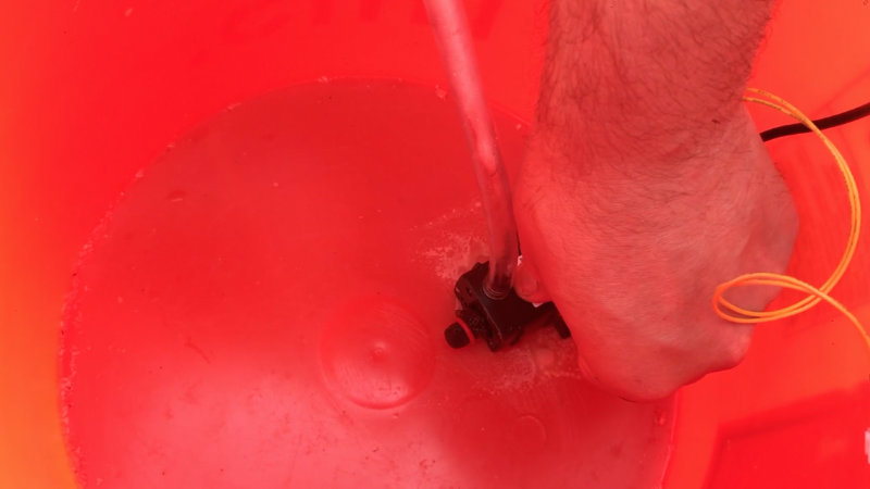
To attach the water level sensor switch to the bucket, just press the bottom of it down on the area you sprayed the glue on and hold it there for a minute or two.
Let the Glue Dry
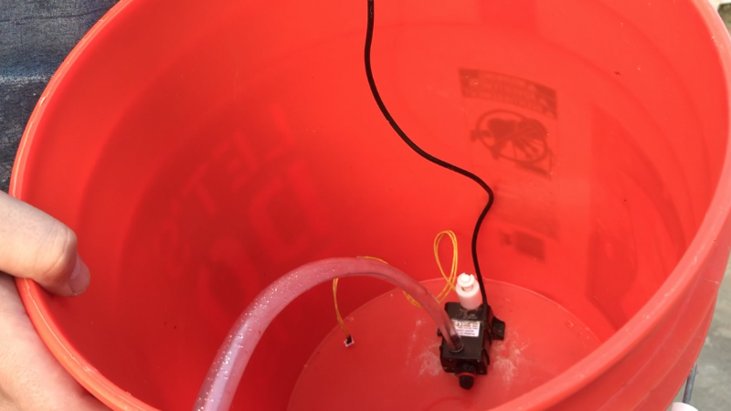
Now we need to let the glue dry for about a half an hour (follow as instructed on the label of the 3M adhesive you are using).
You have the option to glue another pump here as well if you want double the pumping force. One pump will automatically feed a 2-4 plant setup, whereas 2 pumps are recommended for automatically watering a 4-8 plant cultivation setup.
Attaching the Horizontal Water Level Sensor Switch
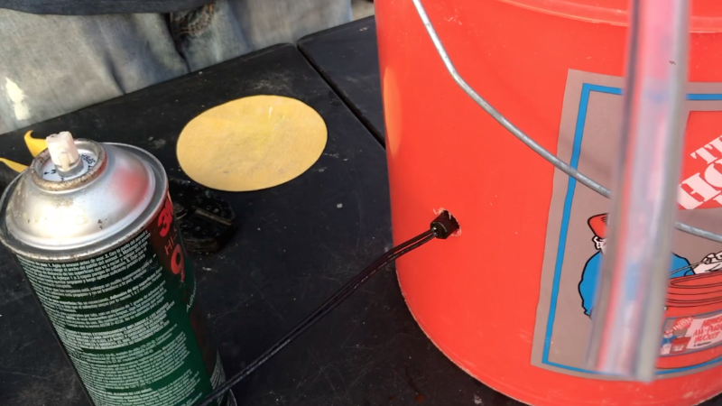
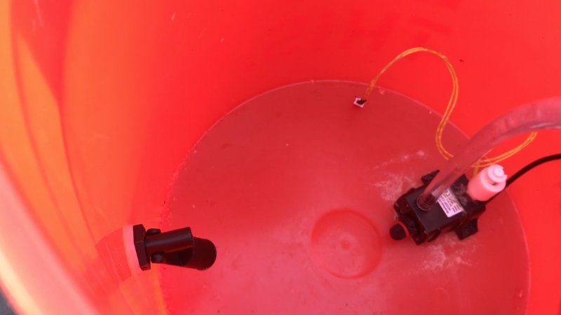
Now we remove the nut and guide the horizontal water level sensor switch through the 1/2" hole we drilled earlier with the washer on the inside. Orient the level switch so it falls near perpendicular without water and it holds straight with water present. Be sure to place the rubber washer between the inside of the bucker and the level switch from the inside. Apply the nut on the back of the water level switch outside the bucket and tighten so you can see some pressure indention on the rubber washer - and avoid over tightening the nut.
Pulling the Wires Through to the Outside
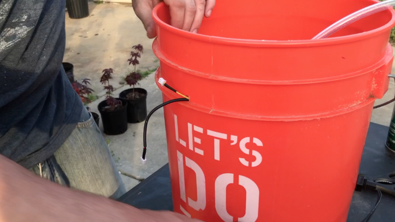
Feed the snap connectors and wiring from the water pump and vertical water level sensor switch assembly through the 1/4" hole towards the top of the reservoir. Pull the connector for a second water pump as well if you decided to add two pumps instead of just one.
Attaching the Wires to the Base Board
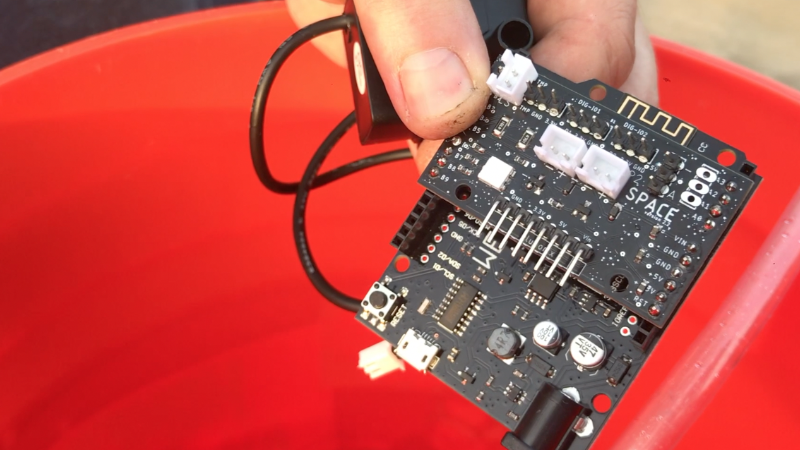
All we need to do is plug in 3 connectors.
Plug the horizontal water level sensor switch (yellow wires) into the top left connector of the board (Digital Pullup Channel #1).
Plug the vertical water level sensor switch (black wires) into the top left two pins of Digital Pullup Channel #2 on the board.
Plug the submersible water pump into the center left connector (Motor / Switch Channel 1) on the board.
If using a second submersible water pump, plug that into the center right connector (Motor / Switch Channel 2) on the board.
Now login to your Adosia account to setup and configure your device programming.