Build a Simple UV Photography Box
by NotLikeALeafOnTheWind in Design > Photography
13856 Views, 82 Favorites, 0 Comments
Build a Simple UV Photography Box
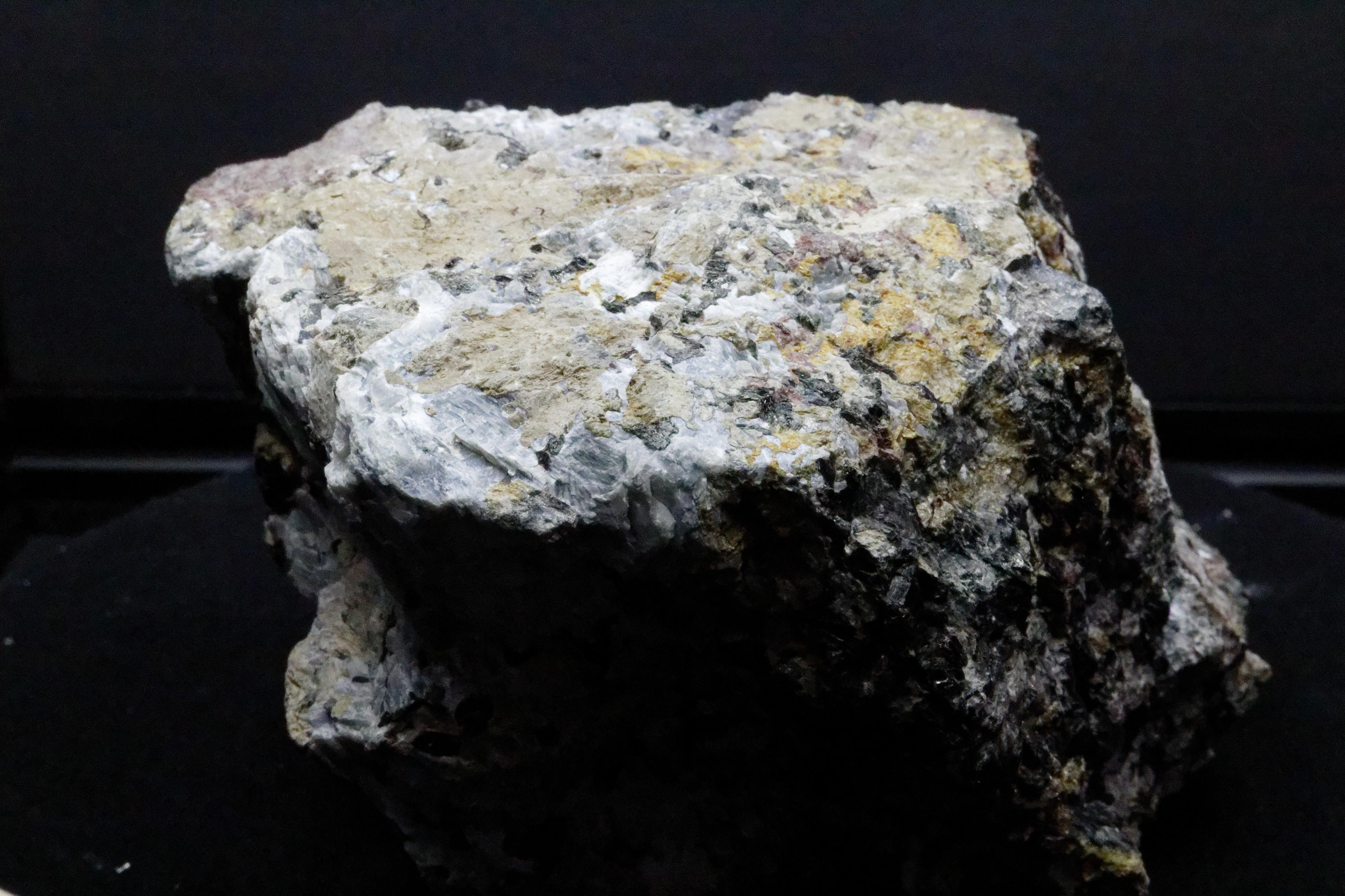
I was too young to remember which museum I was in, but I remember the button. The magic button that turned on the special lights made the brown and dull rocks glow. Glow with colors I had never seen before. I was mesmerized. More than fifty years later, when some marketing types asked, "How do we show the between UVA and UVC," I had the answer. Rocks.
This instructable is the great grand-stepchild of that discussion. I added the element of photography to the mix. The question can be rephrased as "How do we safely photograph the amazing colors fluorescent minerals can produce." This is where we are starting our journey.
This instructable used sub-assemblies from two of our other instructables, A Simple Rotating Stage for Photography or Display and Let's Make a Simple Extruded Aluminum Display Cube.
They will instruct you on building the rotating base and assembling the extruded aluminum framework for the dark box. This project should take about two weekends to complete. It requires only basic woodworking skills and electronic skills.
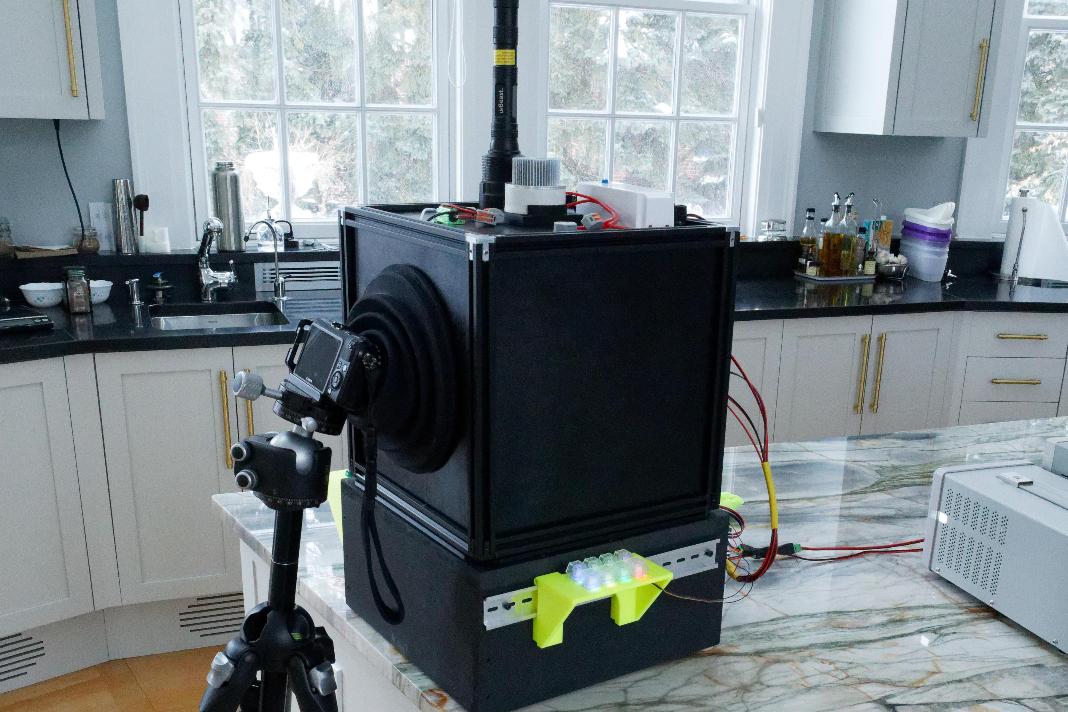
A macro lens and a tripod are a must, as well as a sturdy table to place the dark box. We are going to use long exposures at high f-stops.
First, the obligatory safety warning.
UVC light is dangerous. It causes burns, blindness, and cancer. Because of the pandemic, many devices based on UVC have emerged on the market. For some background reading from the FDA. Article 1 and Article 2. Some other readings can be found in these articles: 1, 2, 3, 4, and 5. Unfortunately, there is a lot of incomplete or disinformation available today, so please carefully check the source of information. This project is undertaken at your own risk and responsibility.
The design philosophy is that we use NO direct exposure to a UV source.
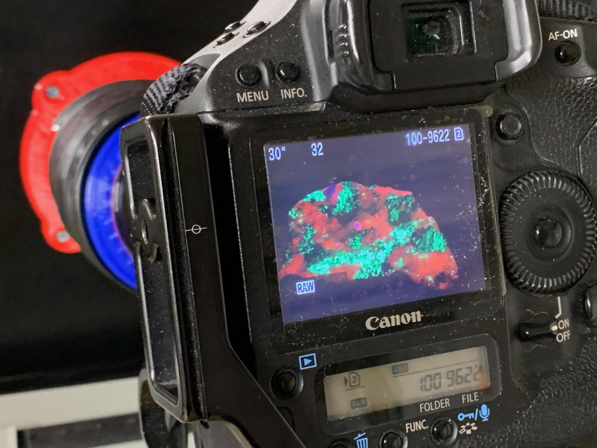
We would strongly recommend against using a direct-view camera for this work. Some of the frequencies of light we are dealing with can be passed through a lens to an eyepiece. Even "safe" UV concentrated through a camera eyepiece is not good for you. If you are using a DLSR, only use it with the mirror locked up and focus on the display. If the mirror has a lockup time-out feature, put a piece of gaffer tape over the eyepiece.
Never look directly into a UV source. Ever.
Yes, we know that black lights are "safe" (UVA). You have seen them in dorm rooms and amusement parks. In those cases, the distance between the source and you can be measured in feet (meters for the enlightened.) Here we are dealing in inches (mm) and have a device that can concentrate and focus the light. Please do not do it.
UVC is not safe. It causes eye damage, burns, and skin cancer. There are about over 100 years of research on this. Ask a welder about "arc eye."
There is evidence that 222nm UVC is safe, but we are aware that there is limited research published and no long-term studies. We hope this pans out, but the research is still under review.
Lastly, some uvc bulbs and lamps produce ozone as a byproduct. Use in a well-ventilated area.
So, let's design for no exposure and leave it at that. You only have two eyes; let's keep them healthy.
Supplies
Supple links can be found in individual sections.
How This Works
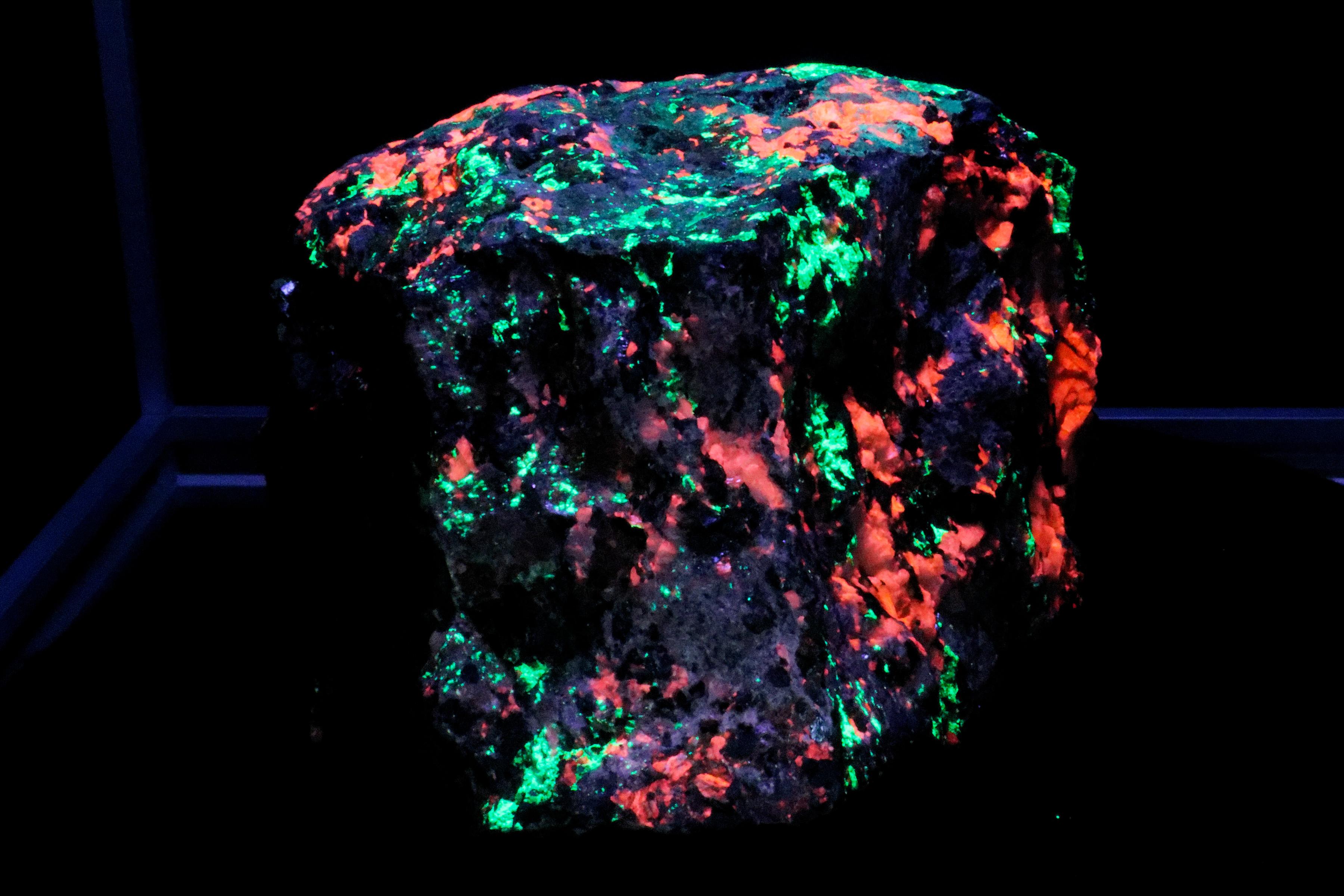
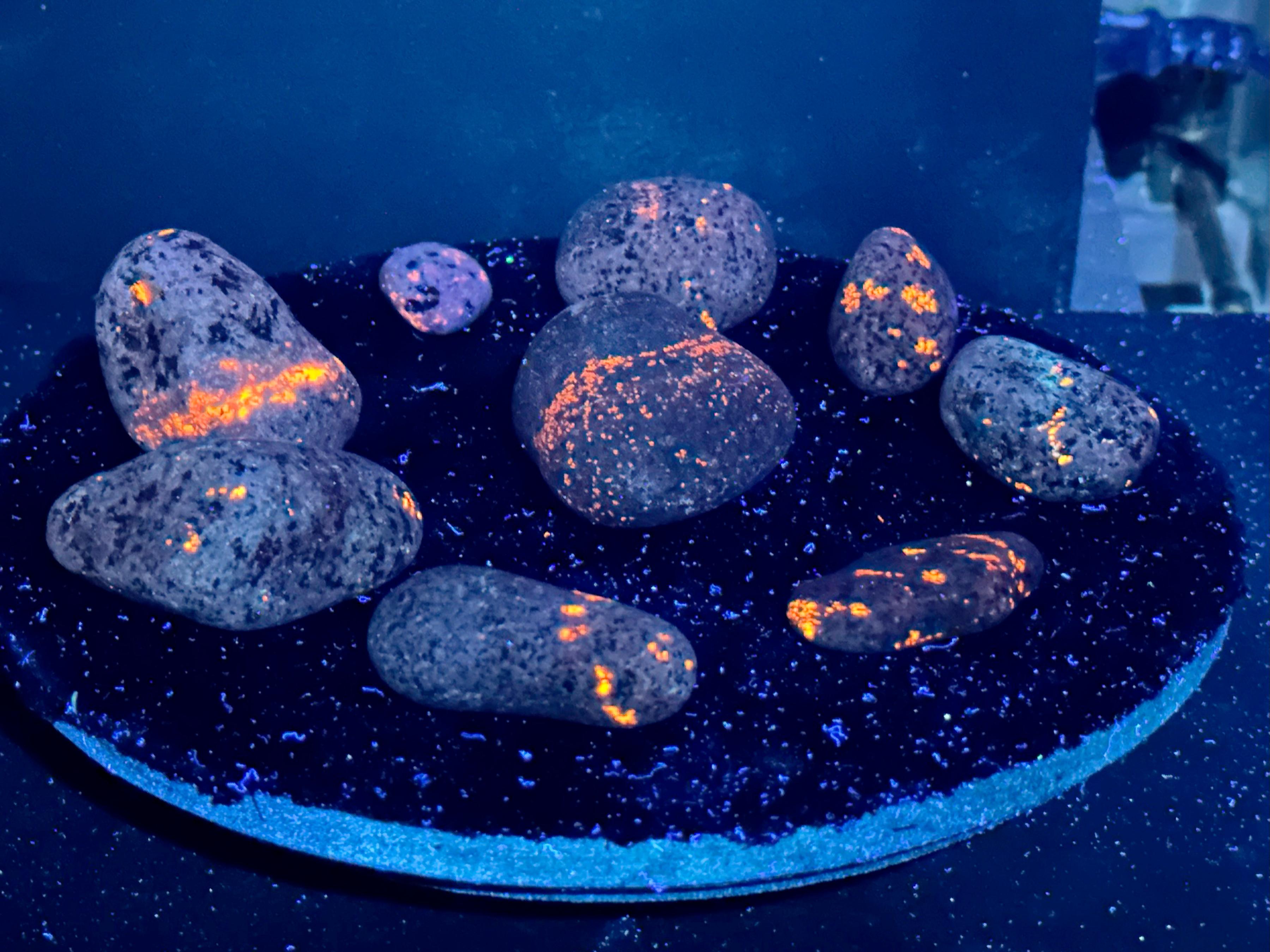
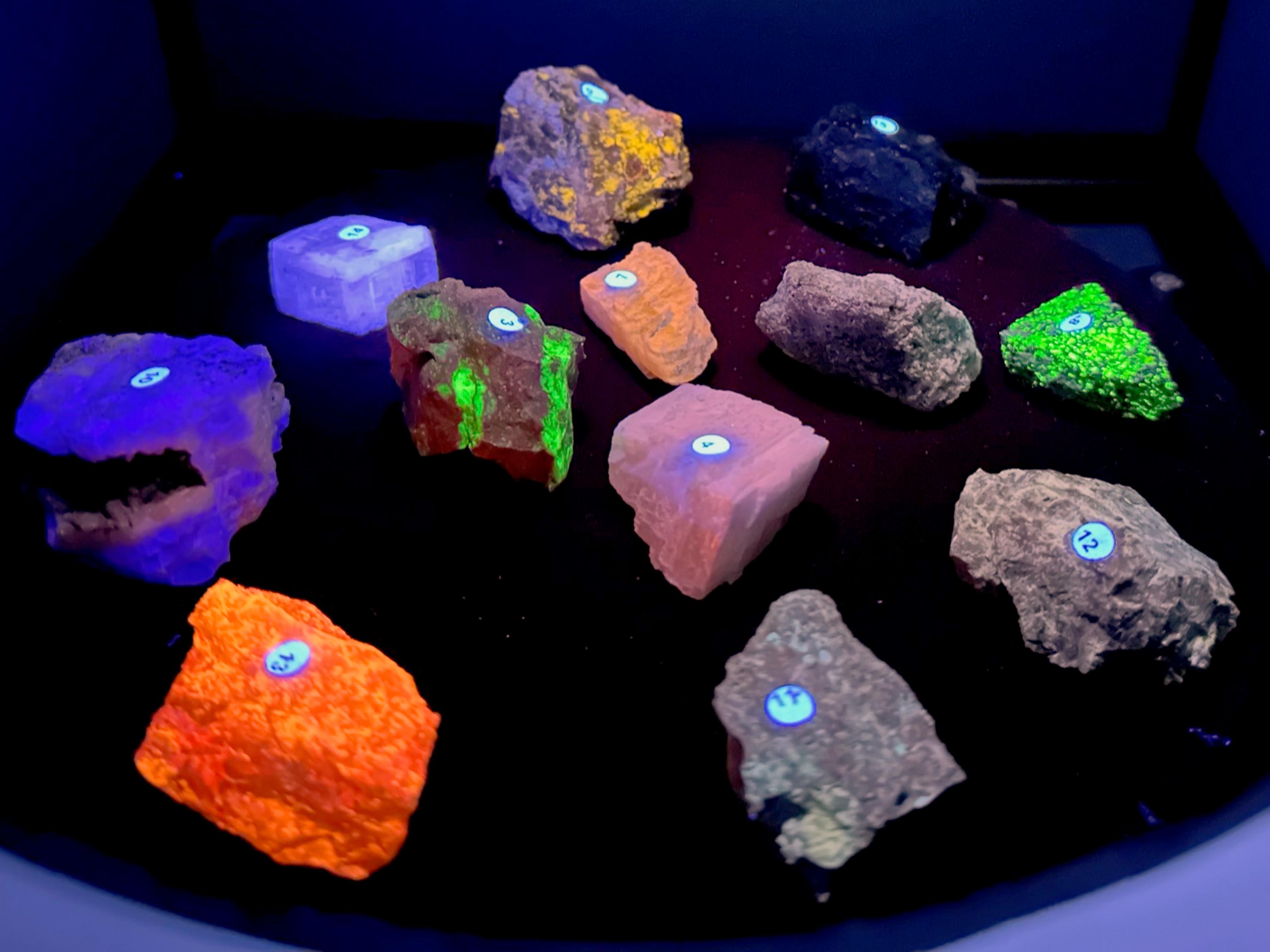
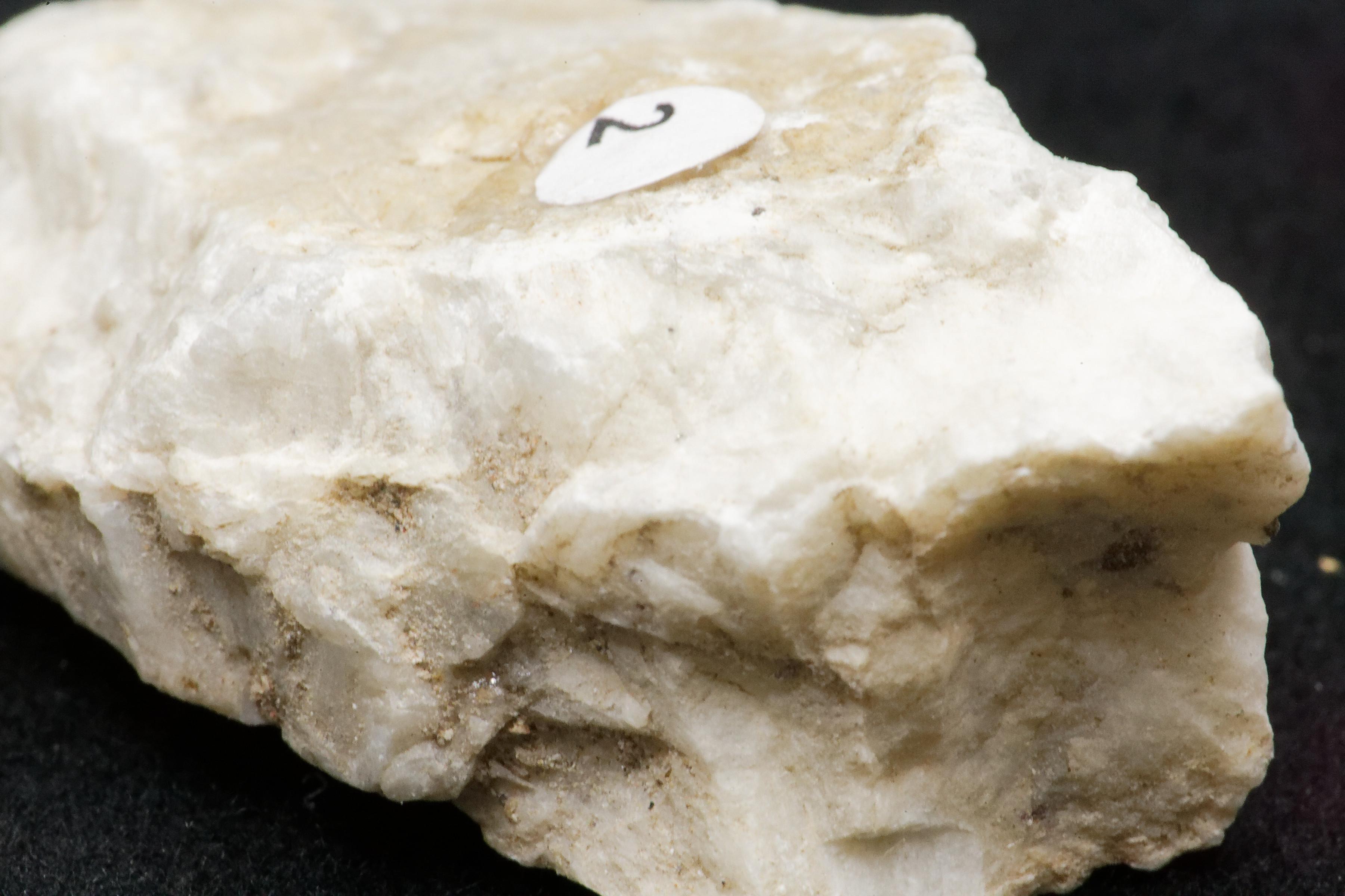
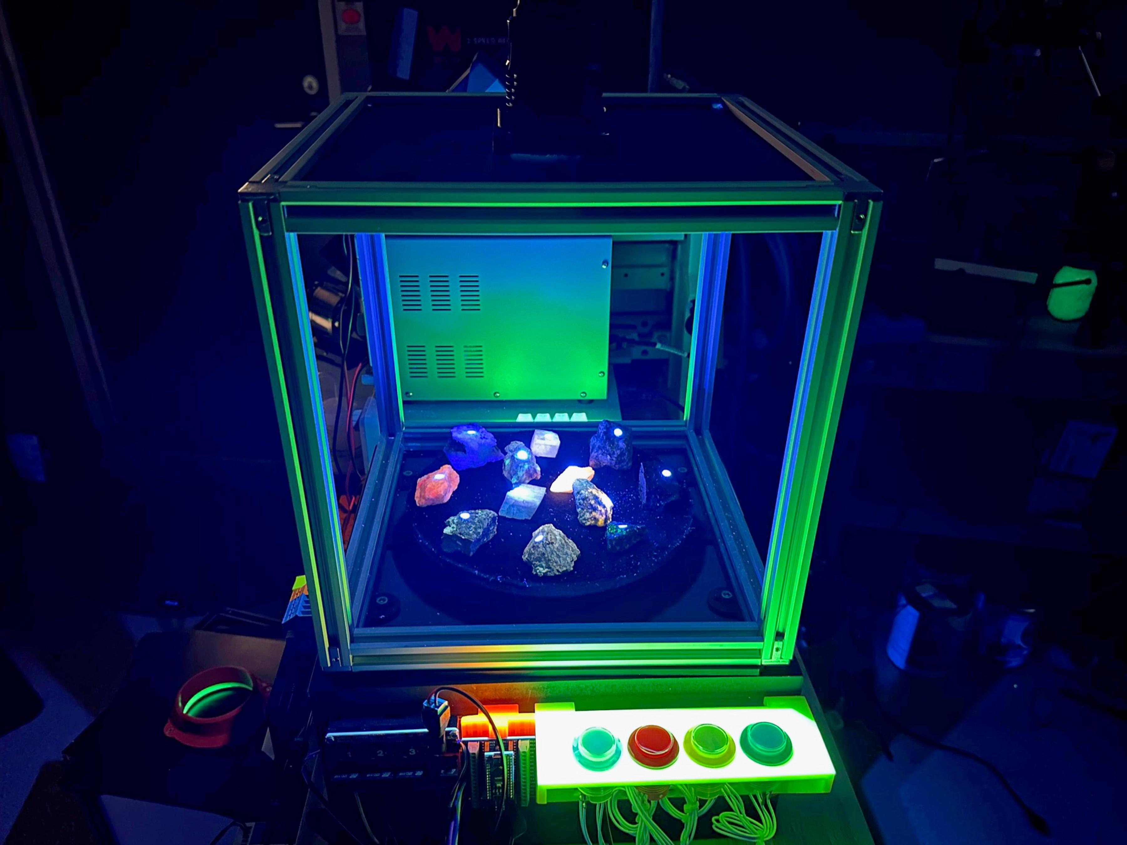
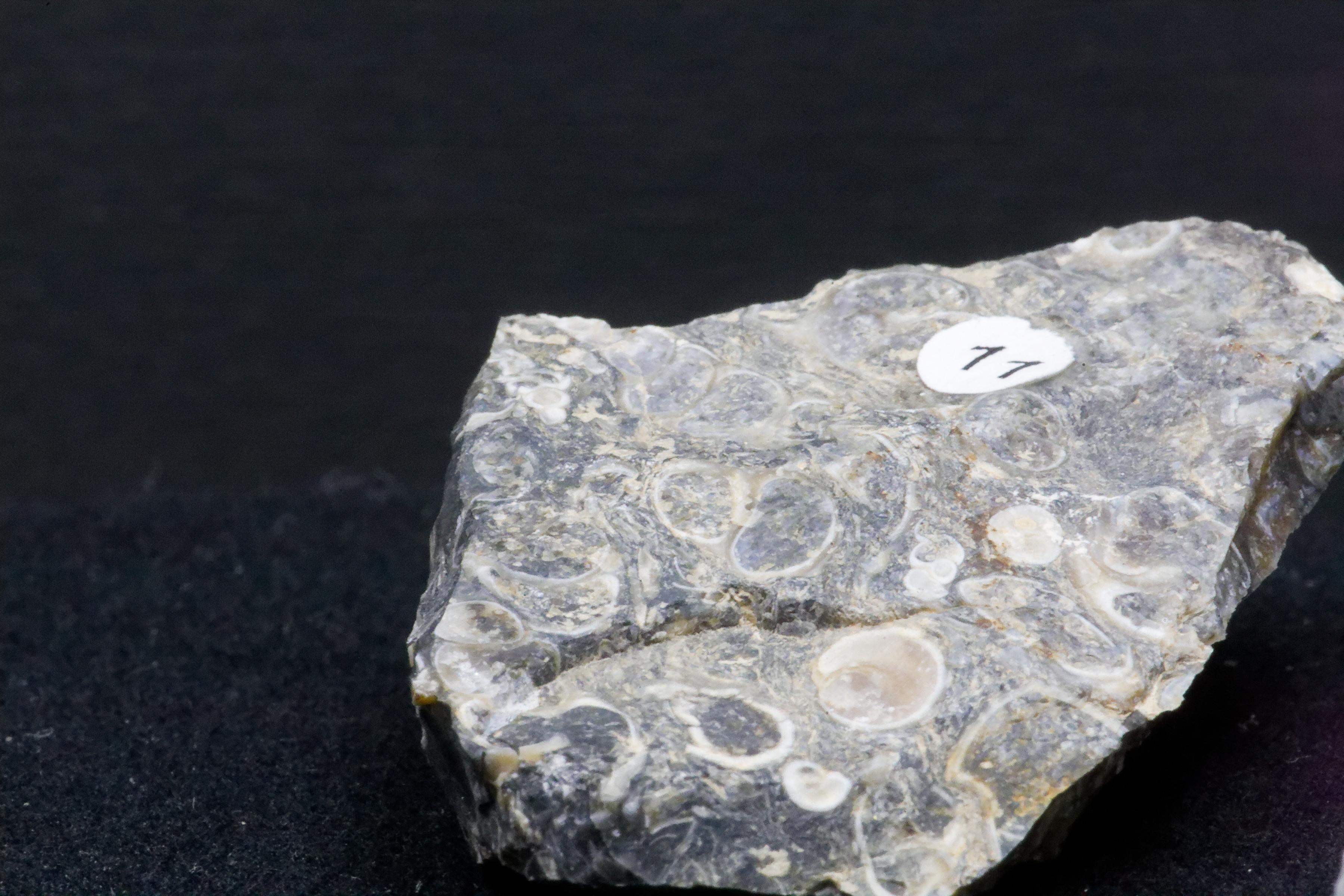
We start with a sample or a collection of samples. This is usually something we know is fluorescent or wish to test for fluorescents.
Fluorescence is a property of a material that, when exposed to energy such as electromagnetic radiation, cause it to emit light. Wikipedia.
We will expose the sample to light in the UV spectrum (~400-100nm), and that energy will cause the sample to emit light in the visible spectrum (~390-750nm). Wikipedia.
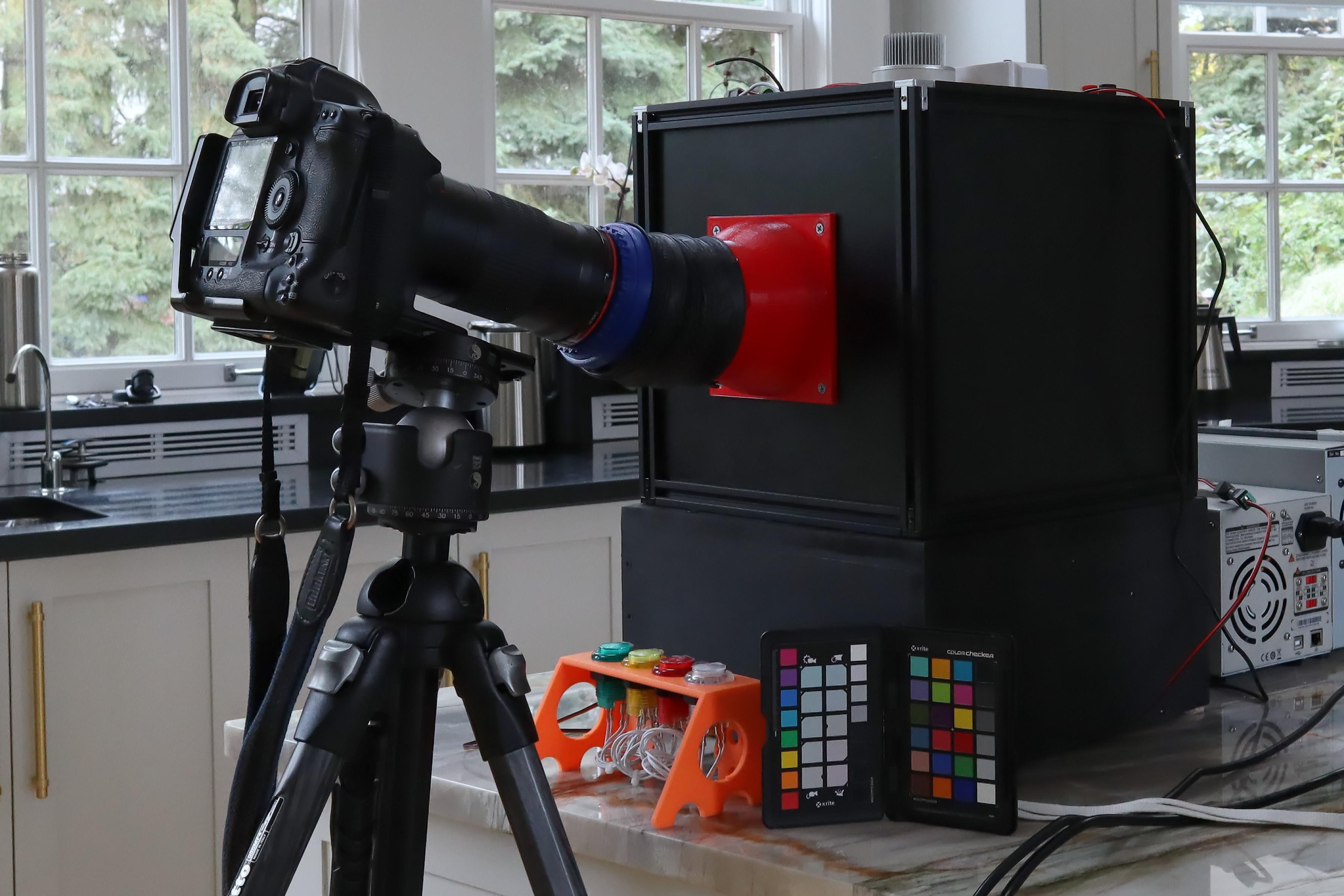
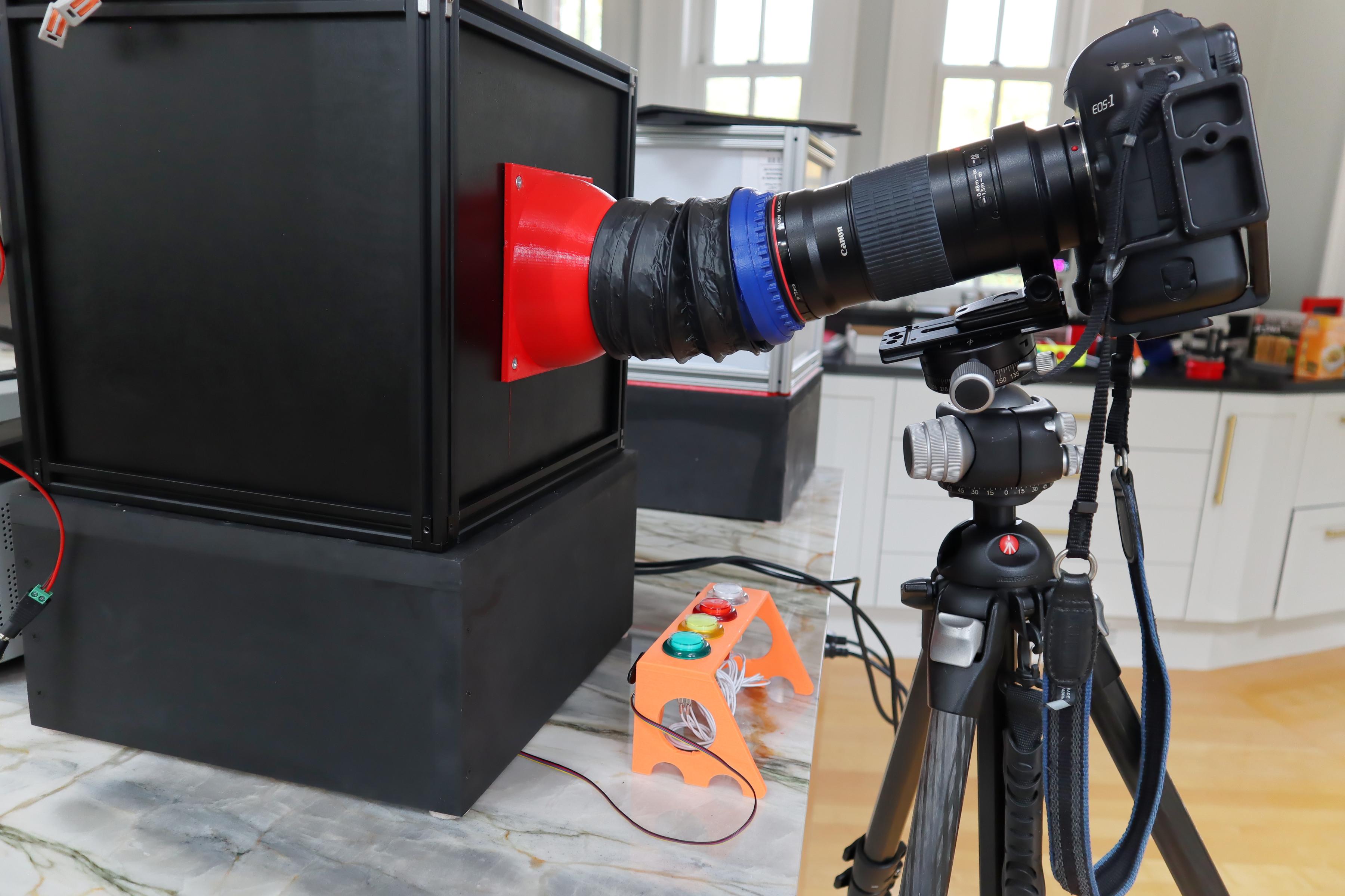
The lights used to illuminate the samples are placed inside a light-tight box. The sample is photographed using a lens (macro or wide angle) and a light-tight bellows that connects the lens to the box.
The sample is placed on a turntable inside the box so it can be externally manipulated from outside the box.
Unlike most photography, the light we try to capture is emitted by the sample, not reflected from an external source. (Think photographing a candle flame in a dark room.) If you are interested, a quick search of the physics of color is an excellent place to start understanding this type of photography.
We usually try to use the maxim depth of field that the lens can provide. We are looking for a reasonable compromise on ISO. So, be prepared for some long exposures. We make good use of the delayed shutter release on our cameras.
An excellent article about fluorescent minerals can be found here.
The Process of Taking a Picture
The process of taking a picture starts with the subject. In this case, the sample of a mineral.
- We place the sample or samples on the turntable.
- We put the dark box over the samples.
- Attach the camera lens to the bellows and the bellows to the dark box
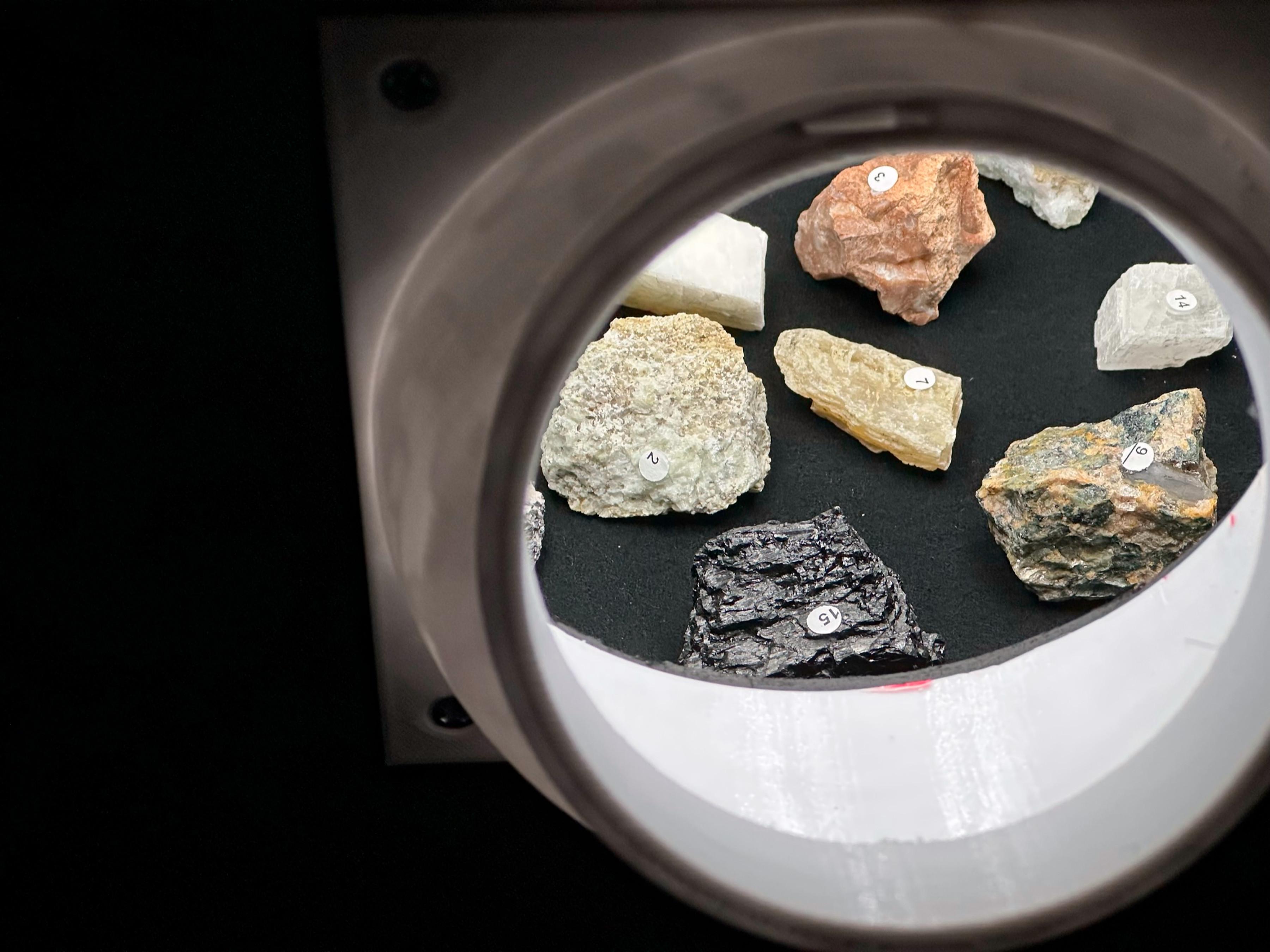
- Turn on the white light and frame the initial shot
- Turn on the first UV source and turn off the white light. Examine the results through the camera and take a picture. Note how well the sample responds to the source
- Turn off the first UV source and turn on the second. Examine the results through the camera and take a shot. note how well the sample is responding to the source
- Repeat with all the UV sources.
- After establishing which sources to use, we used the turntable controls to move the sample to explore the piece.
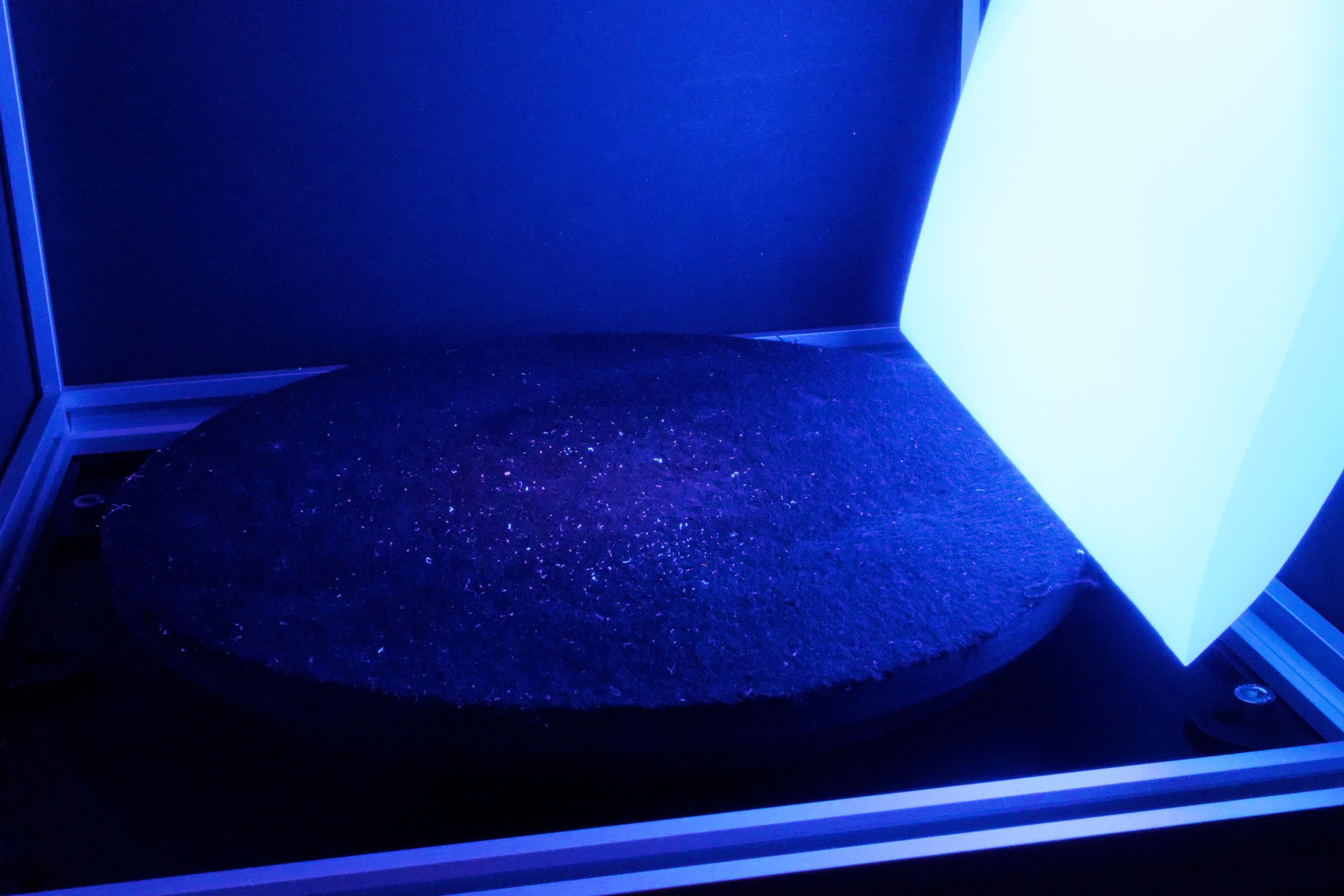
We have the camera mounted on a sturdy tripod with an adjustable head; The camera has a shutter delay of at least two seconds to allow any vibration in the system to dampen before the shutter is released.
It is helpful to have access to a vacuum cleaner when setting up a photo session. The 356nm does an excellent job of iluminintang dust and paper shavings. You will want to remove as much dust as you can.
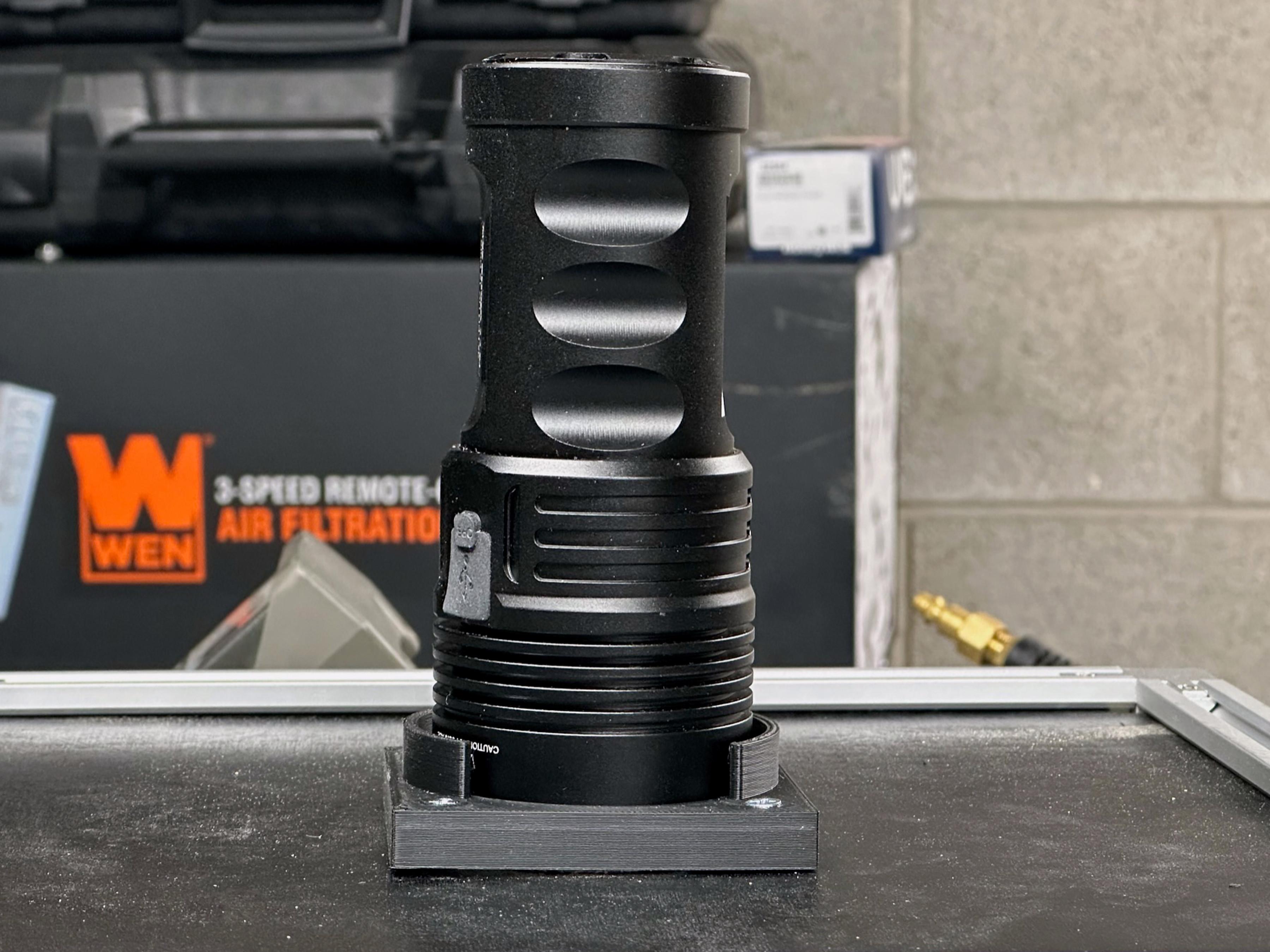
The Light Sources
The box we built was set up for UV light at four different frequency's, 220nm, 265nm, 365nm, ~400nm, and visible light. The sources are diverse, LEDs, lamps, and tubes. They are all either 12V or 24V dc devices or in the form of a flashlight. Some of the sources have a bandpass filter installed. The bandpass filter reduces or eliminates visage light produced by the source.
You can build the project with one or more of the light sources we have used or add additional lights with frequencies of your own choice. We have constantly been amazed at the change in fluorescence that a slight shift in frequency can bring about.
The other thing we need to talk about is bandpass filters. Most of the light sources we use do not have bandpass filters installed. We are waiting on several different frequencies of bandpass filters and will update the design if testing shows a marked improvement in picture quality.
A Wider Prespective
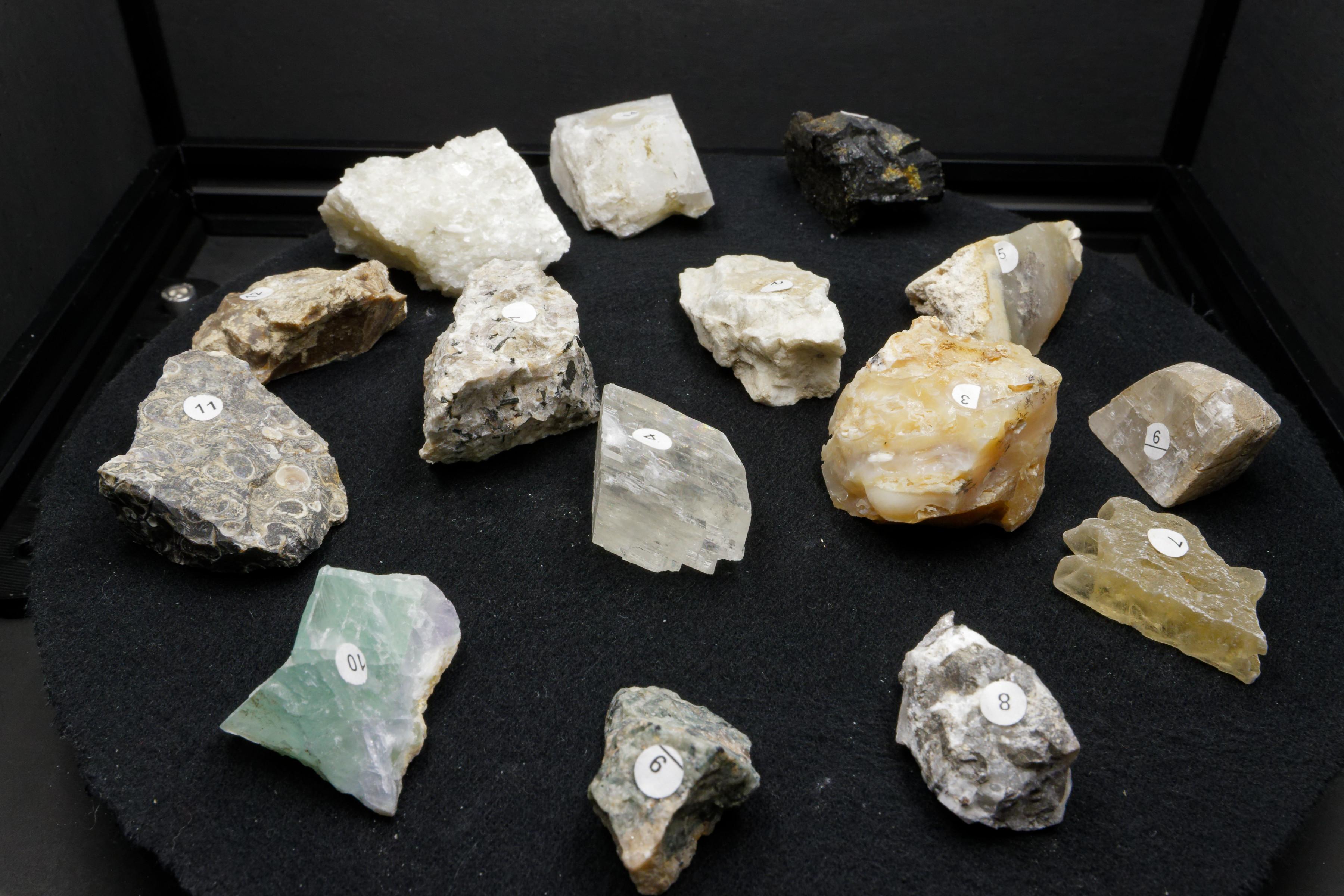
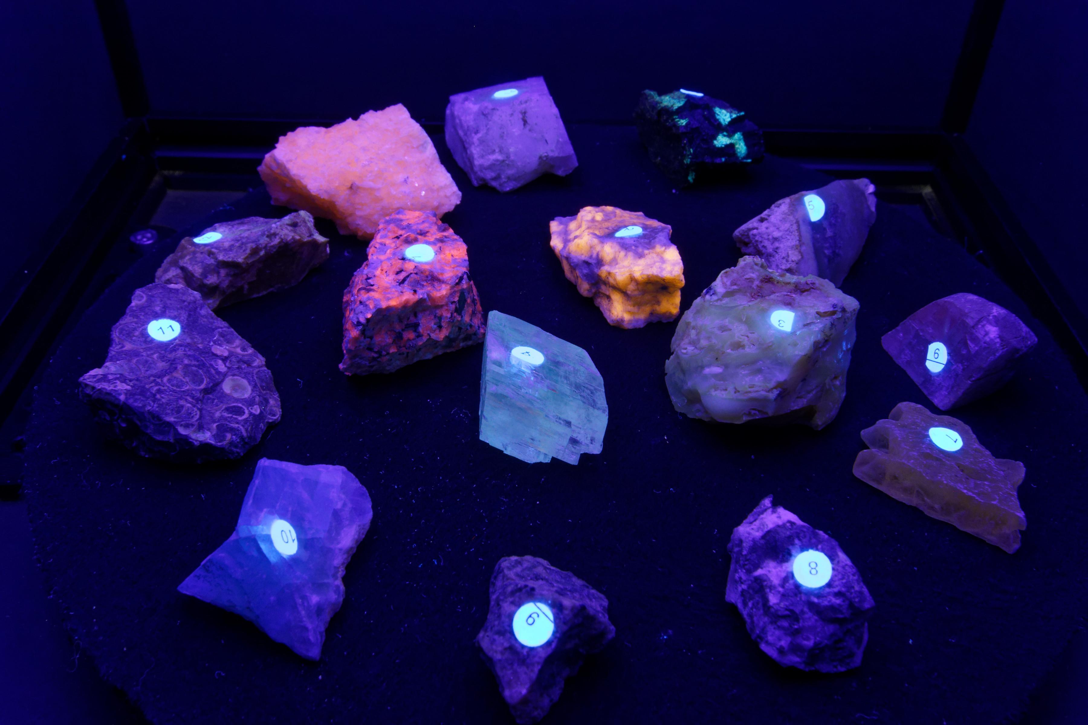
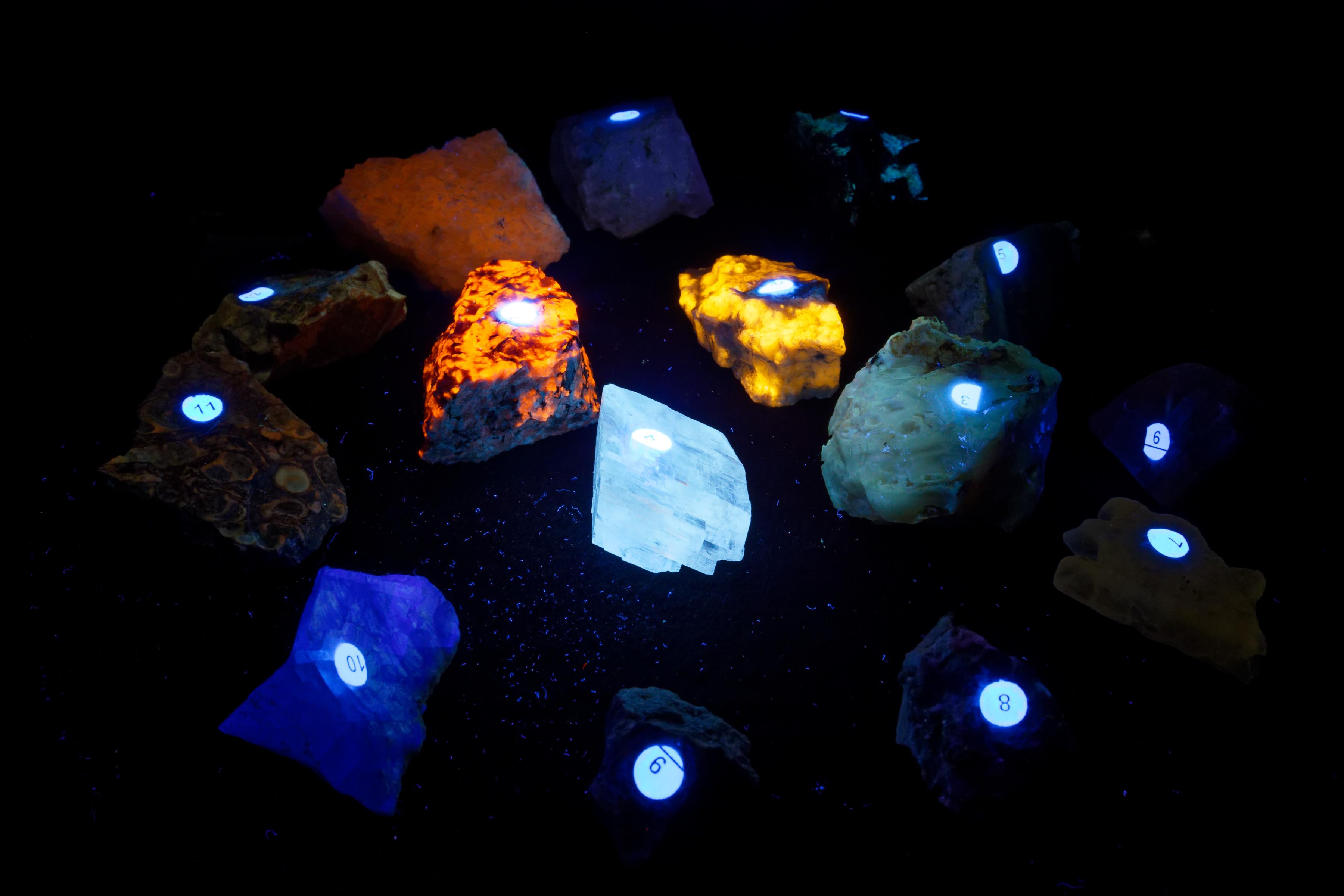
This picture series was taken with an 18-70 zoom lens at f22. The focus was manually set using the 6000K LEDs and not touched for the subsequent images. The lighting controller (and a manual flashlight swap) stepped the lamination source for each image.
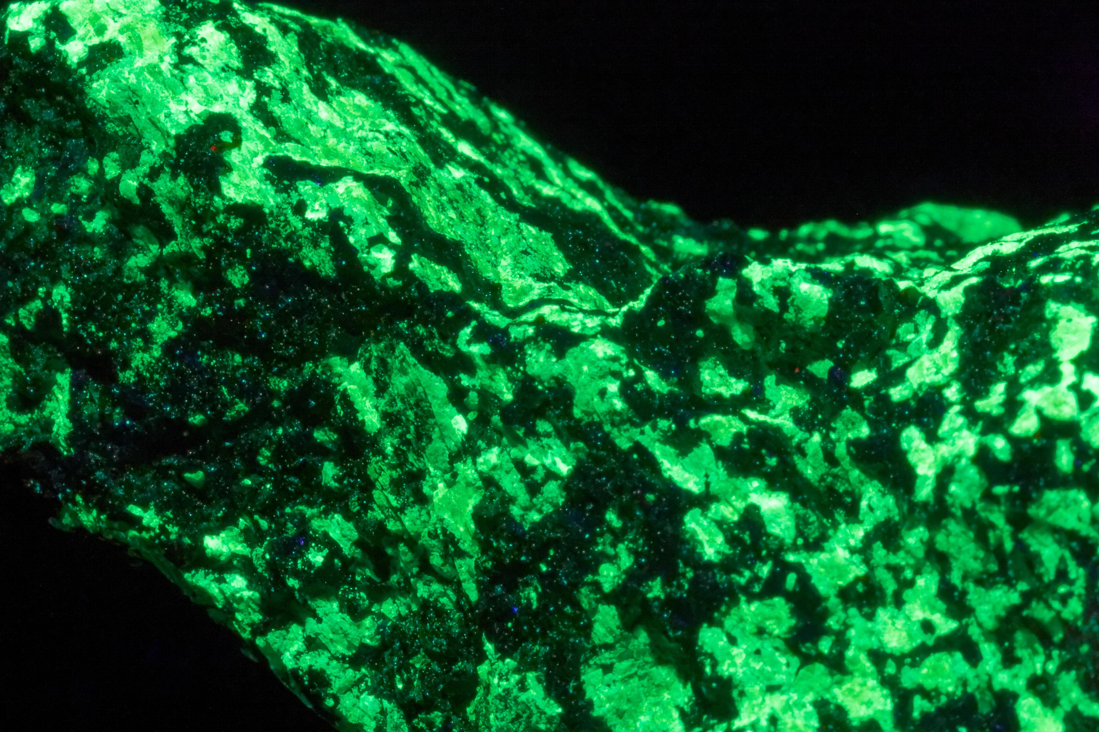
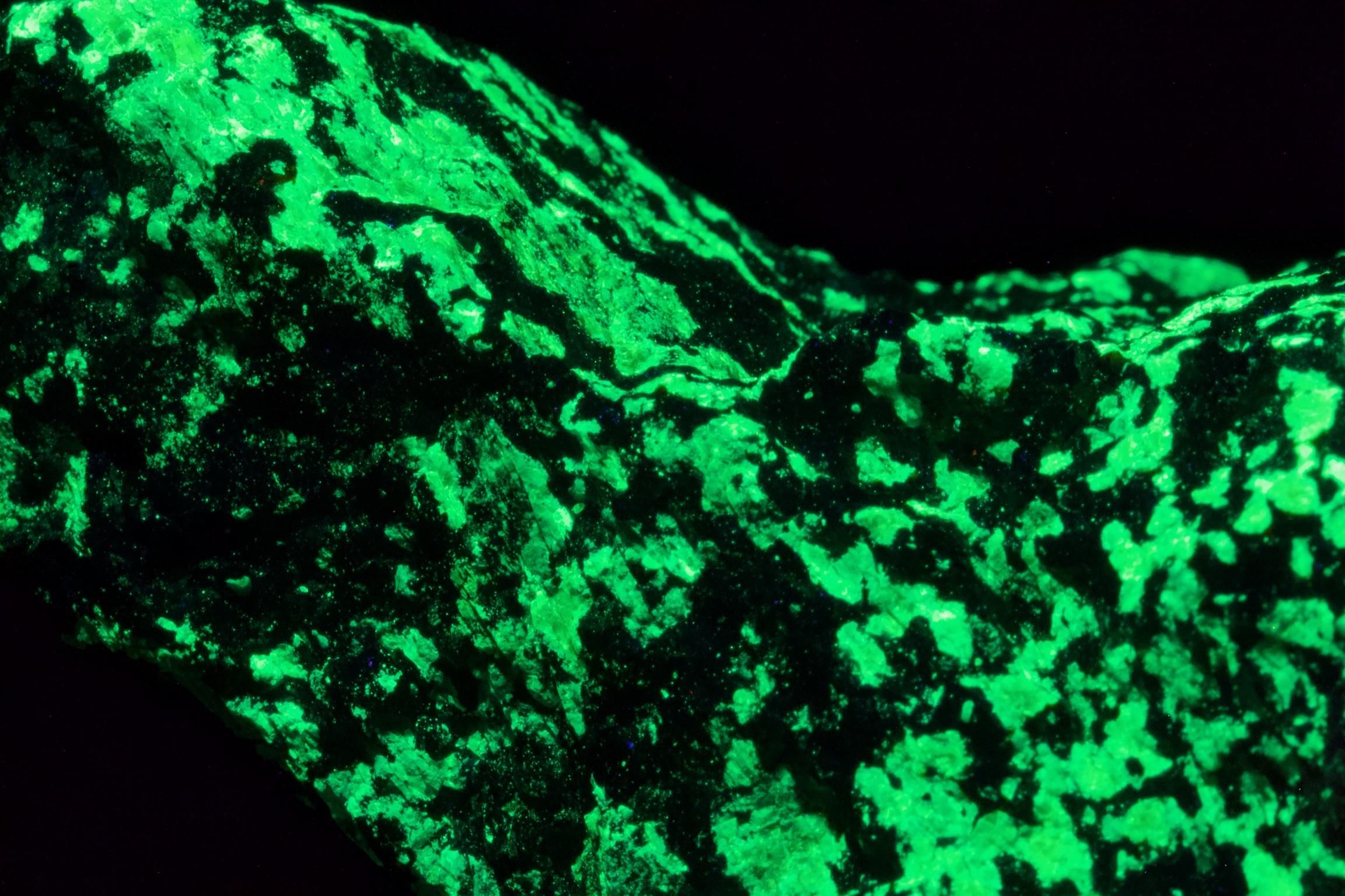
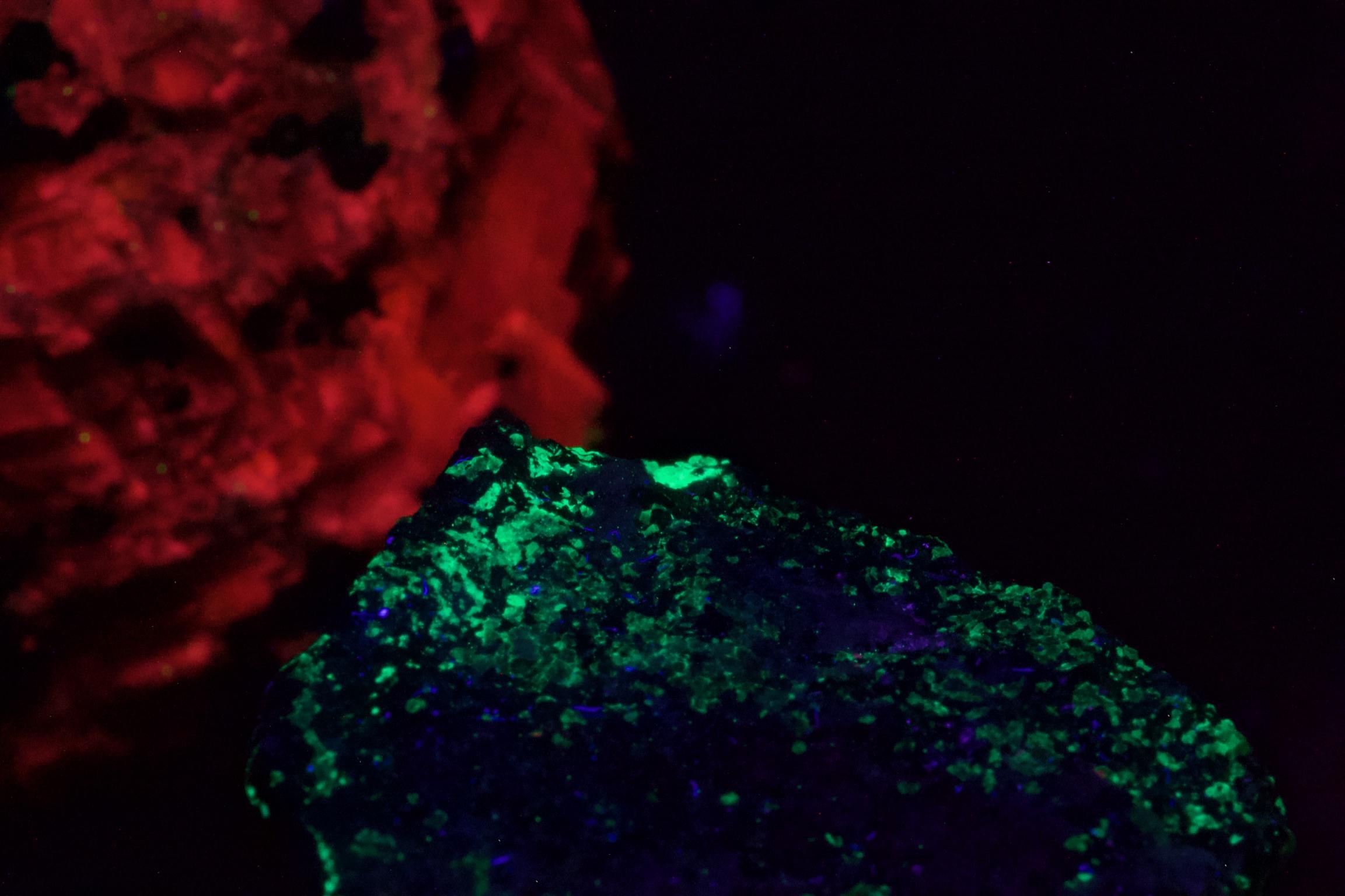
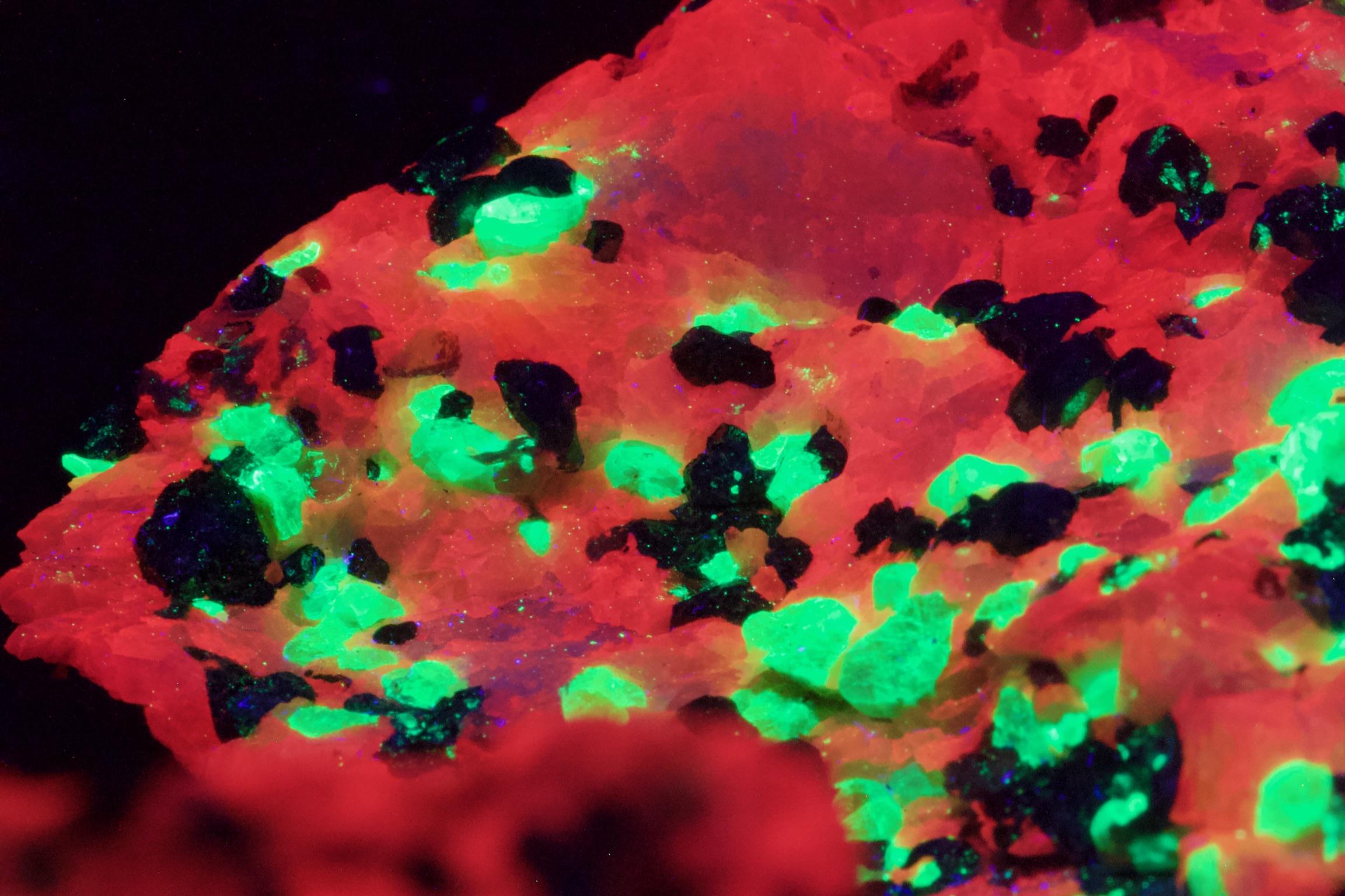
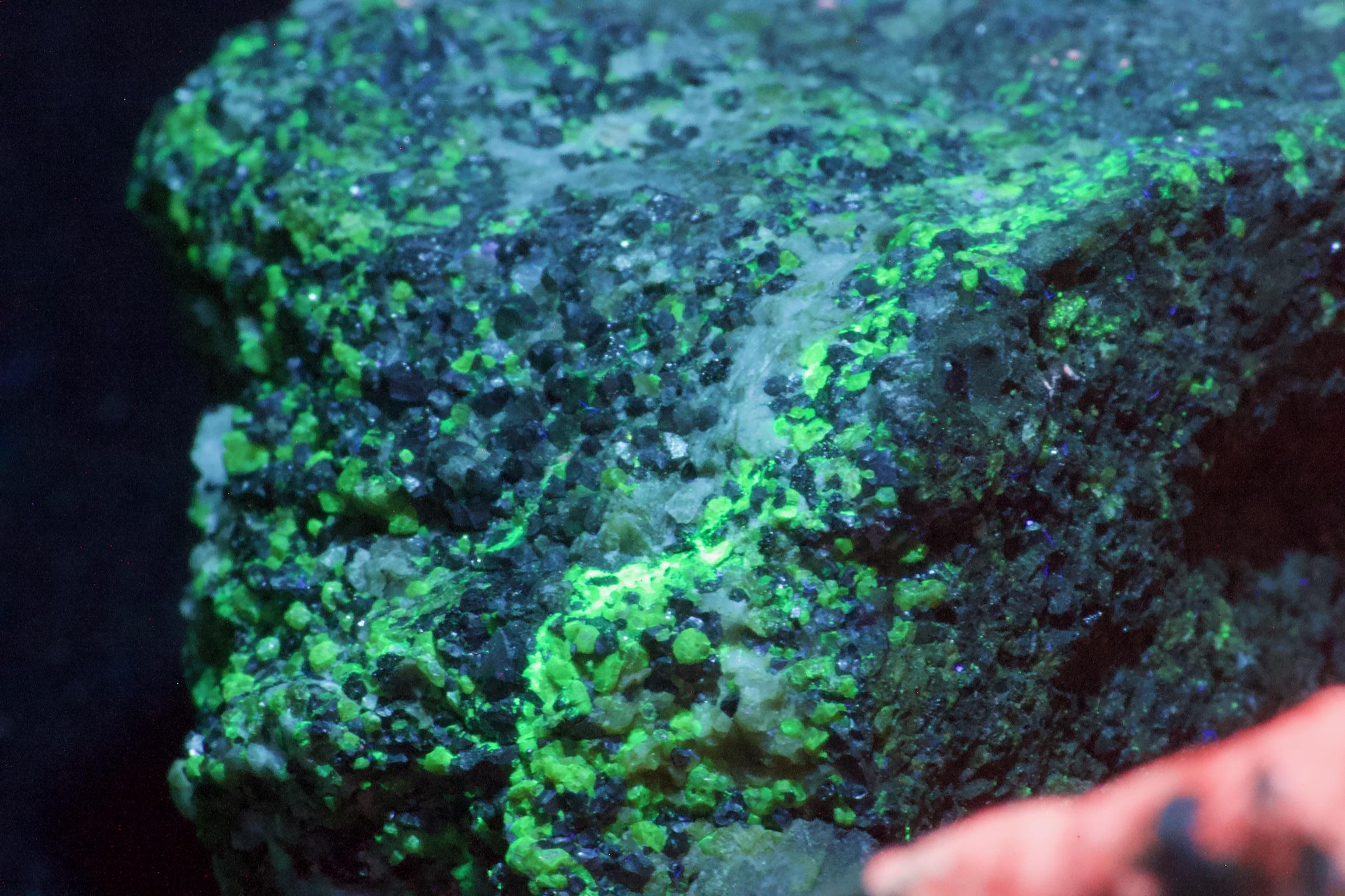
Macro Lenses
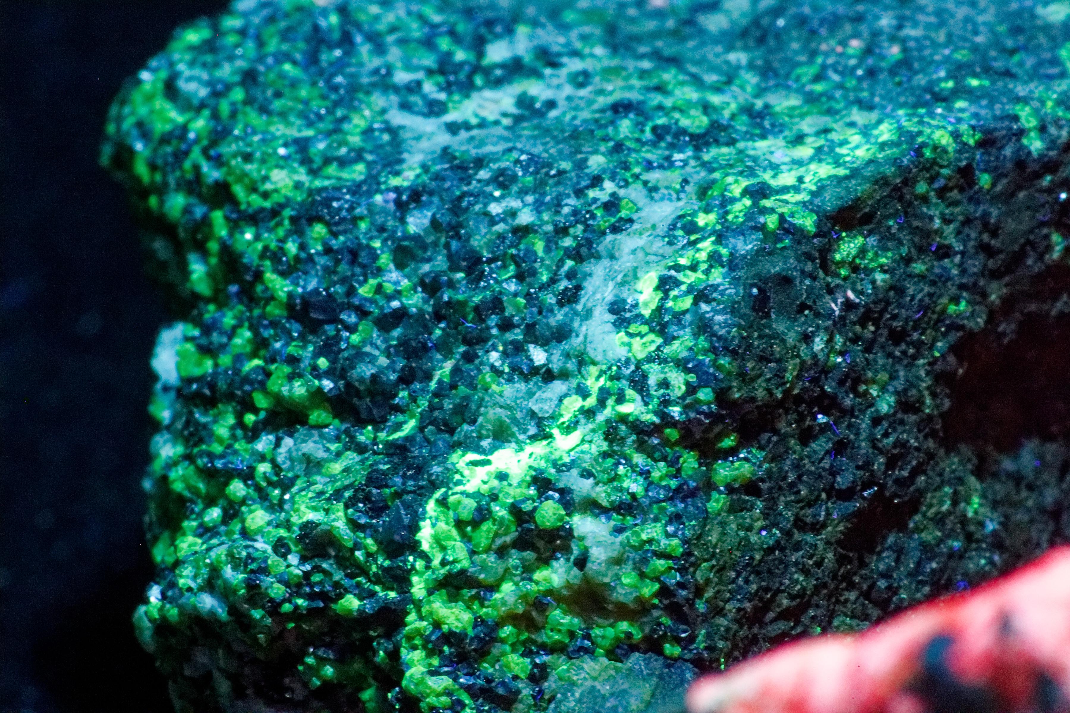
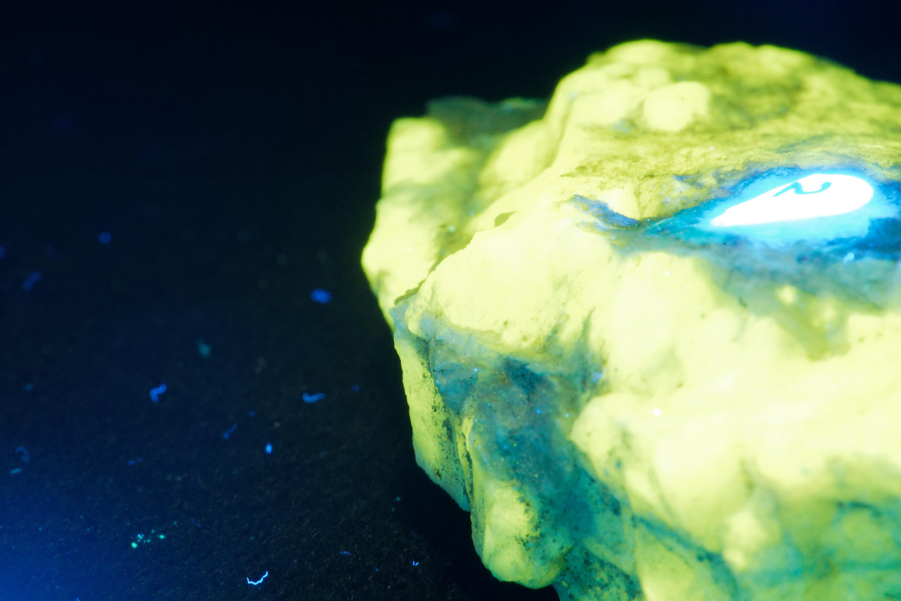
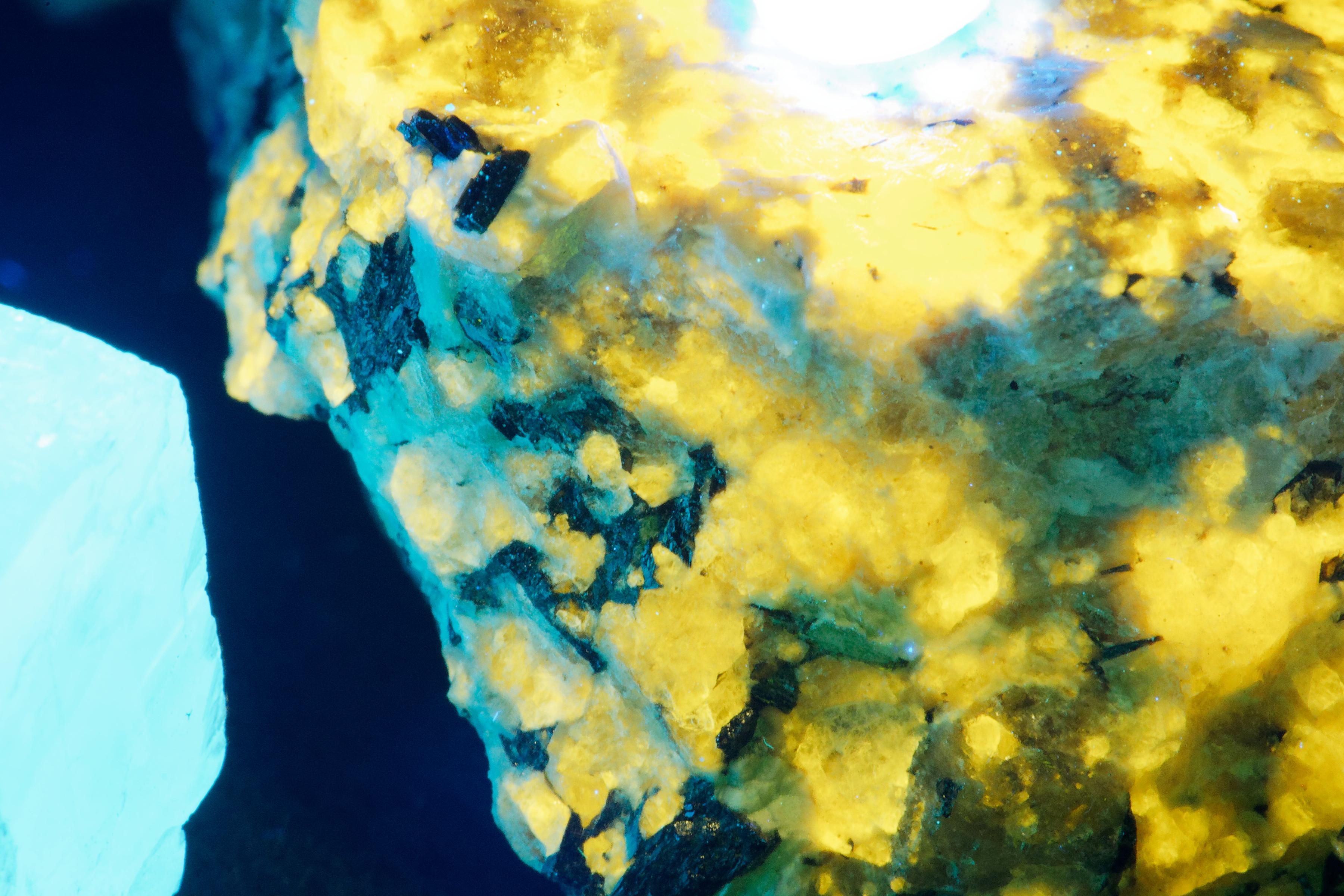
Macro photography is one of the most exciting aspects of uv photography. It allows for the exploration of small areas of a specimen to the point where you can watch individual portions of the rock respond to different frequencies of the UV spectrum. The setup we used will be described in the section about the bellows.
You will need a good, solid, vibration-free surface to place the dark box and a good tripod: a high-power macro lens or macro zoom and a little patience.
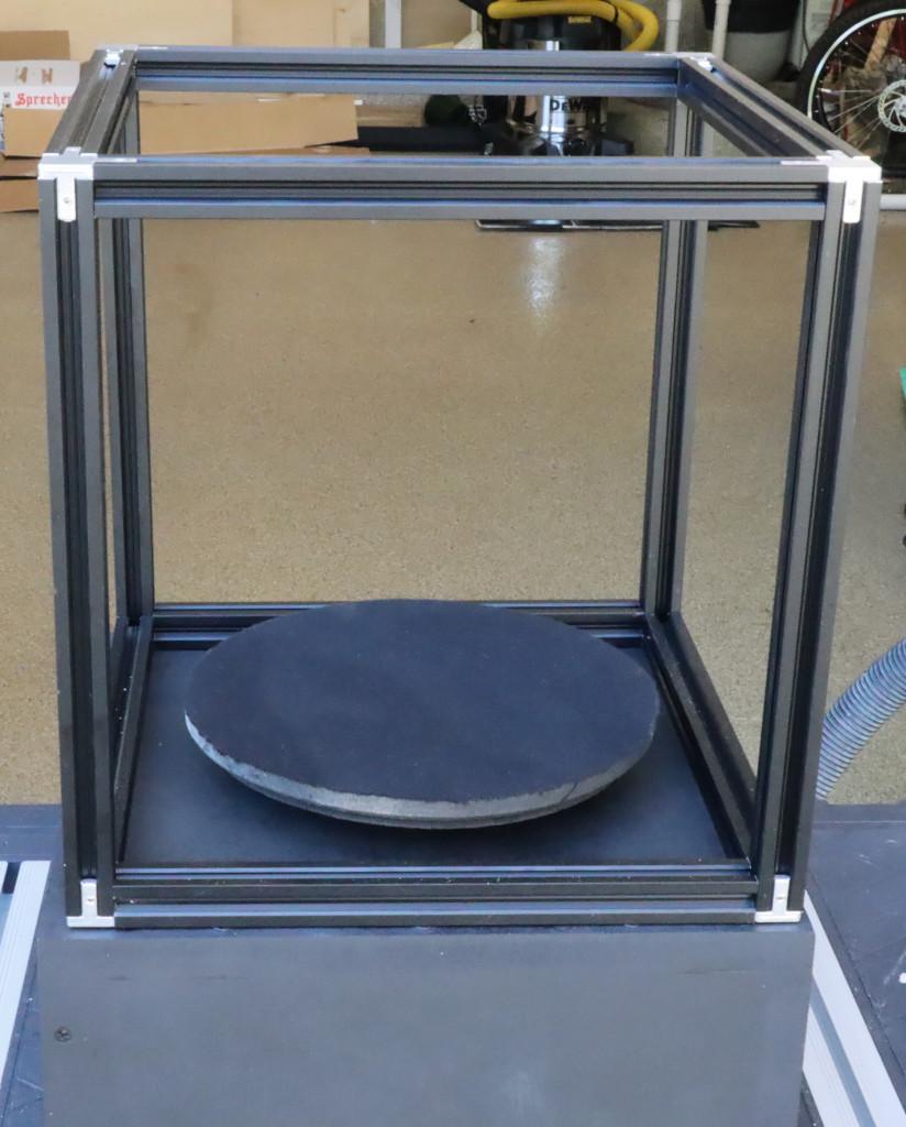
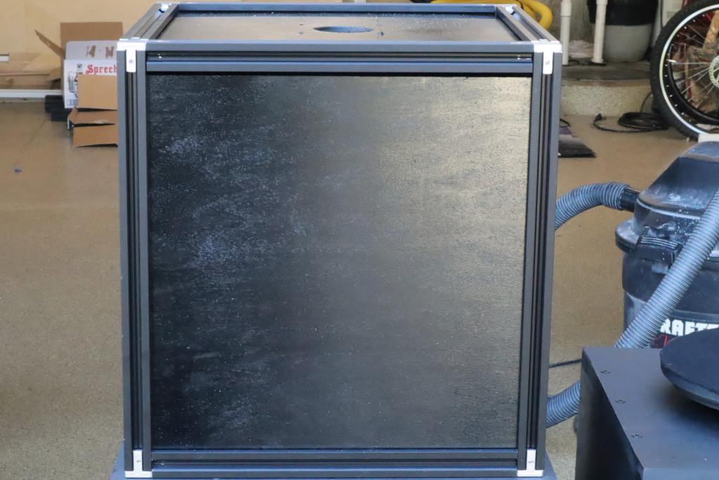
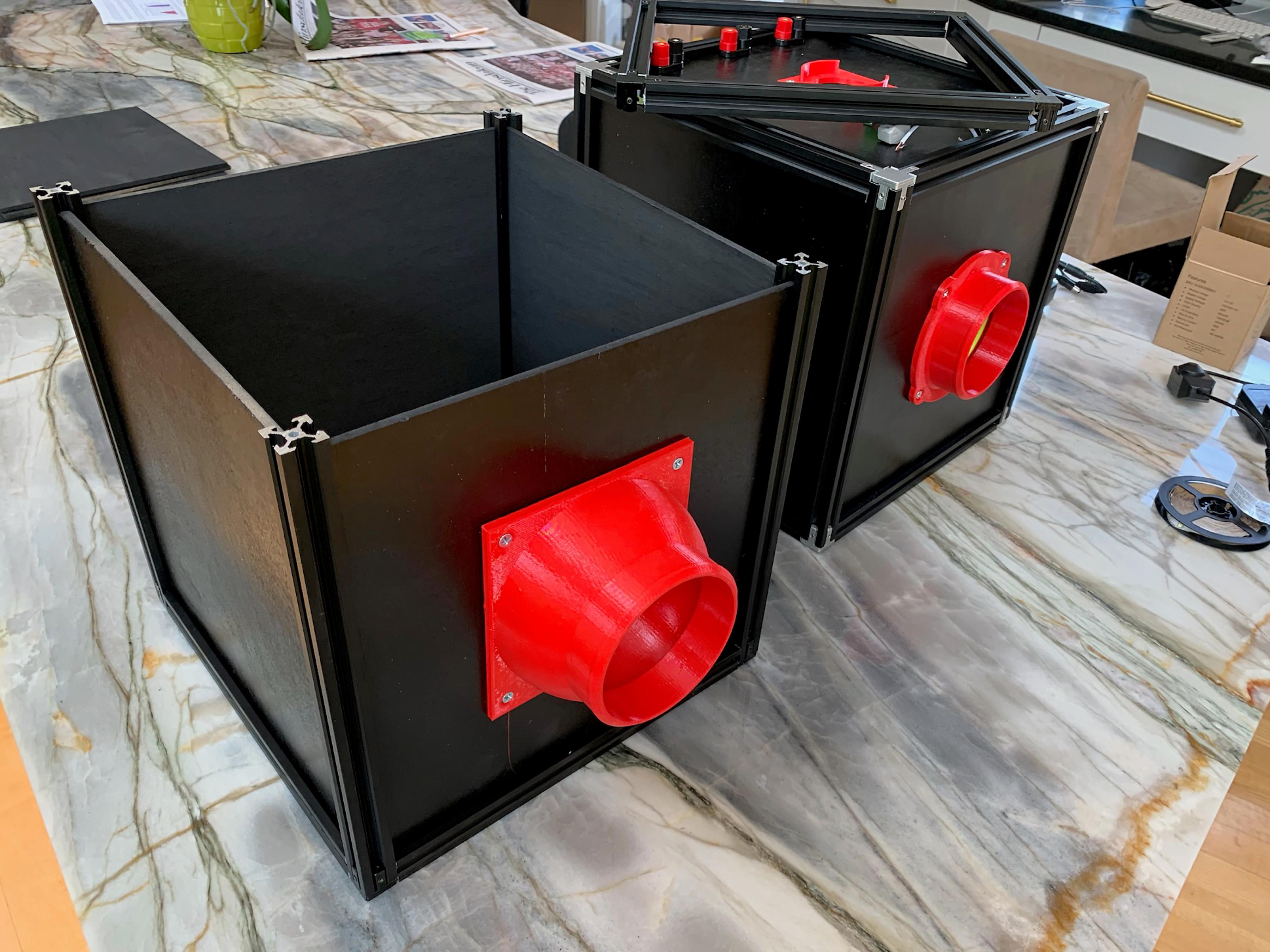
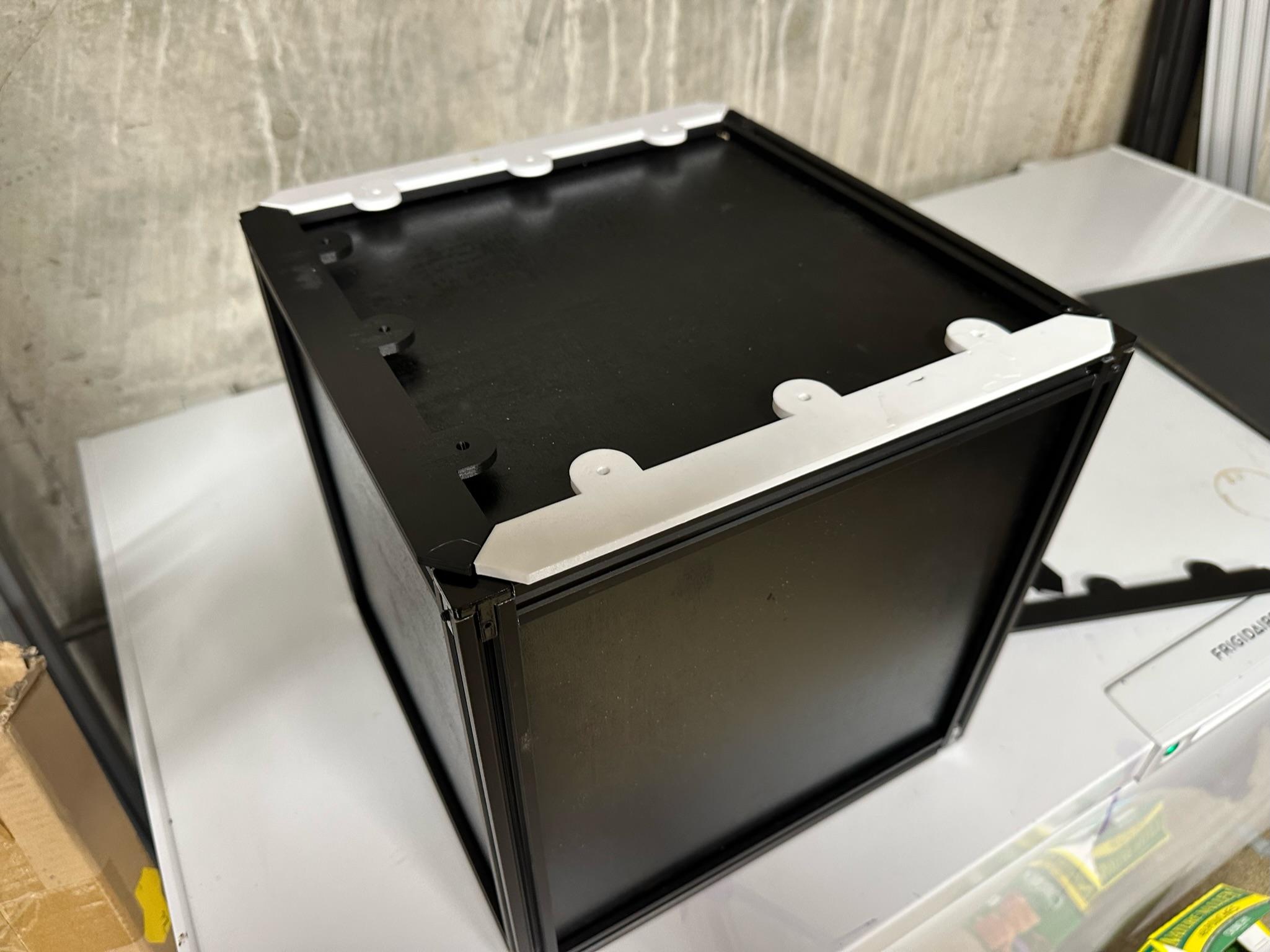
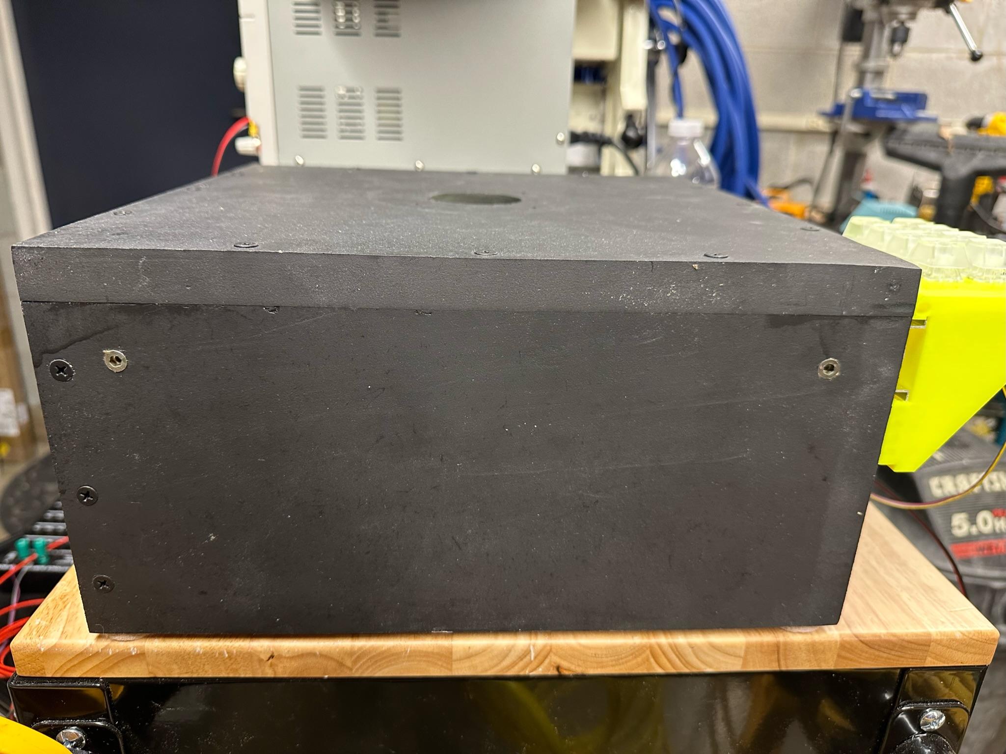
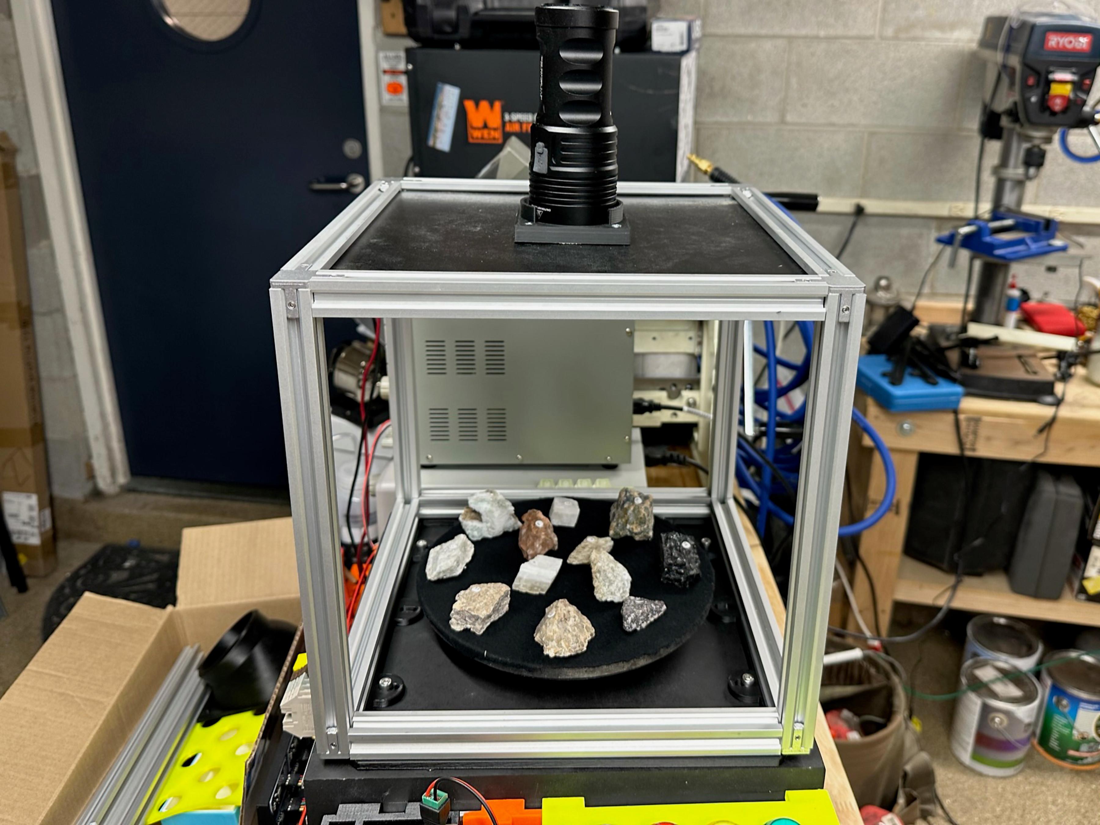
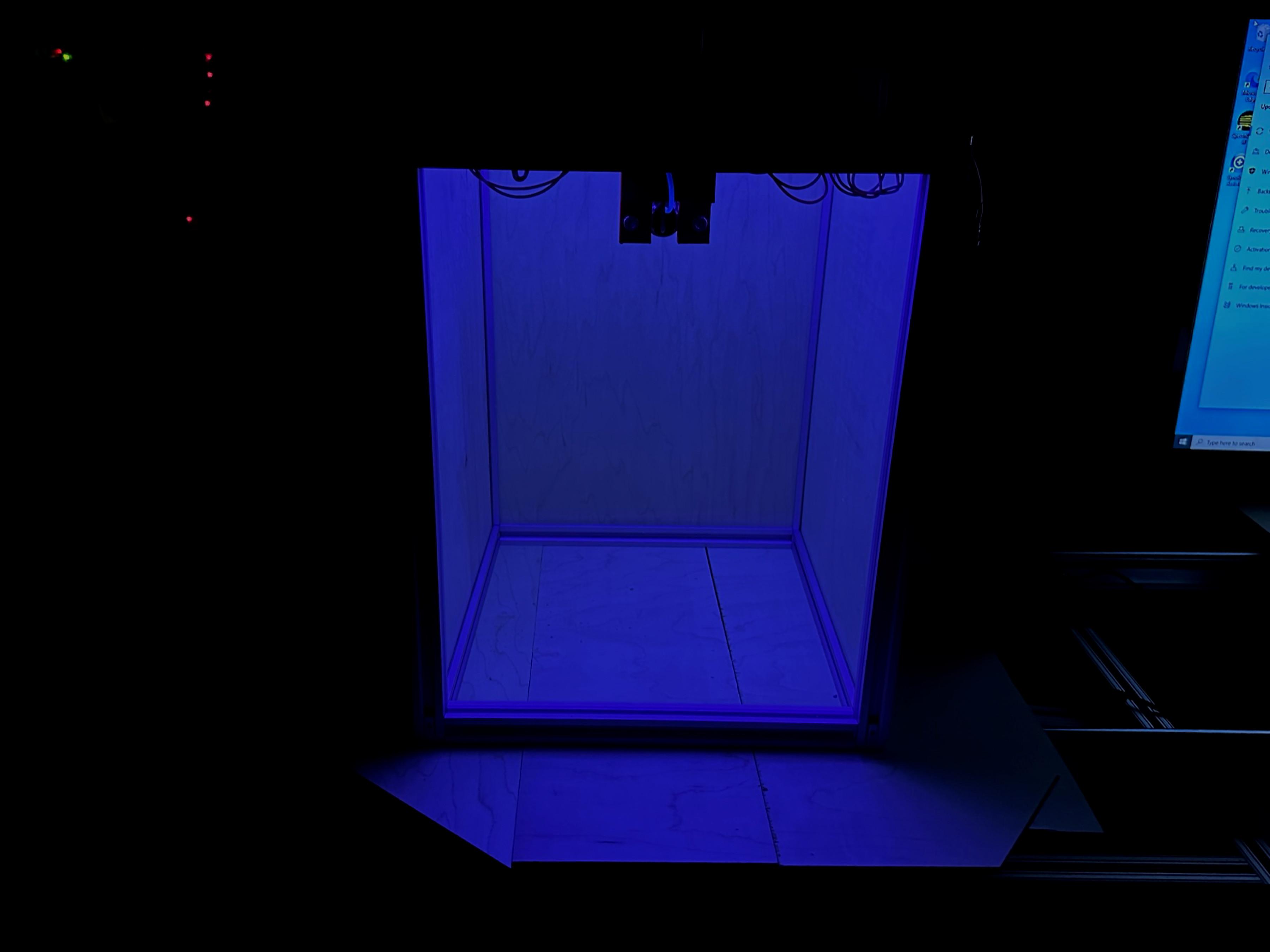
The Dark Box

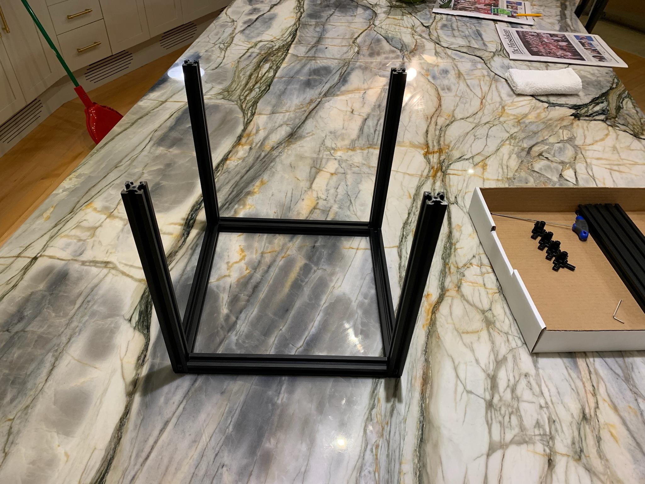
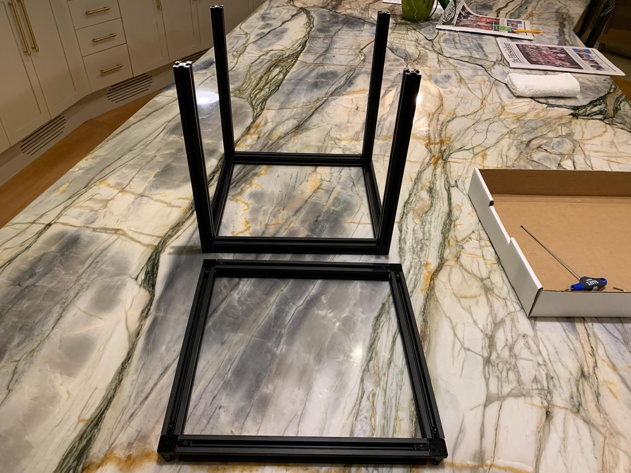
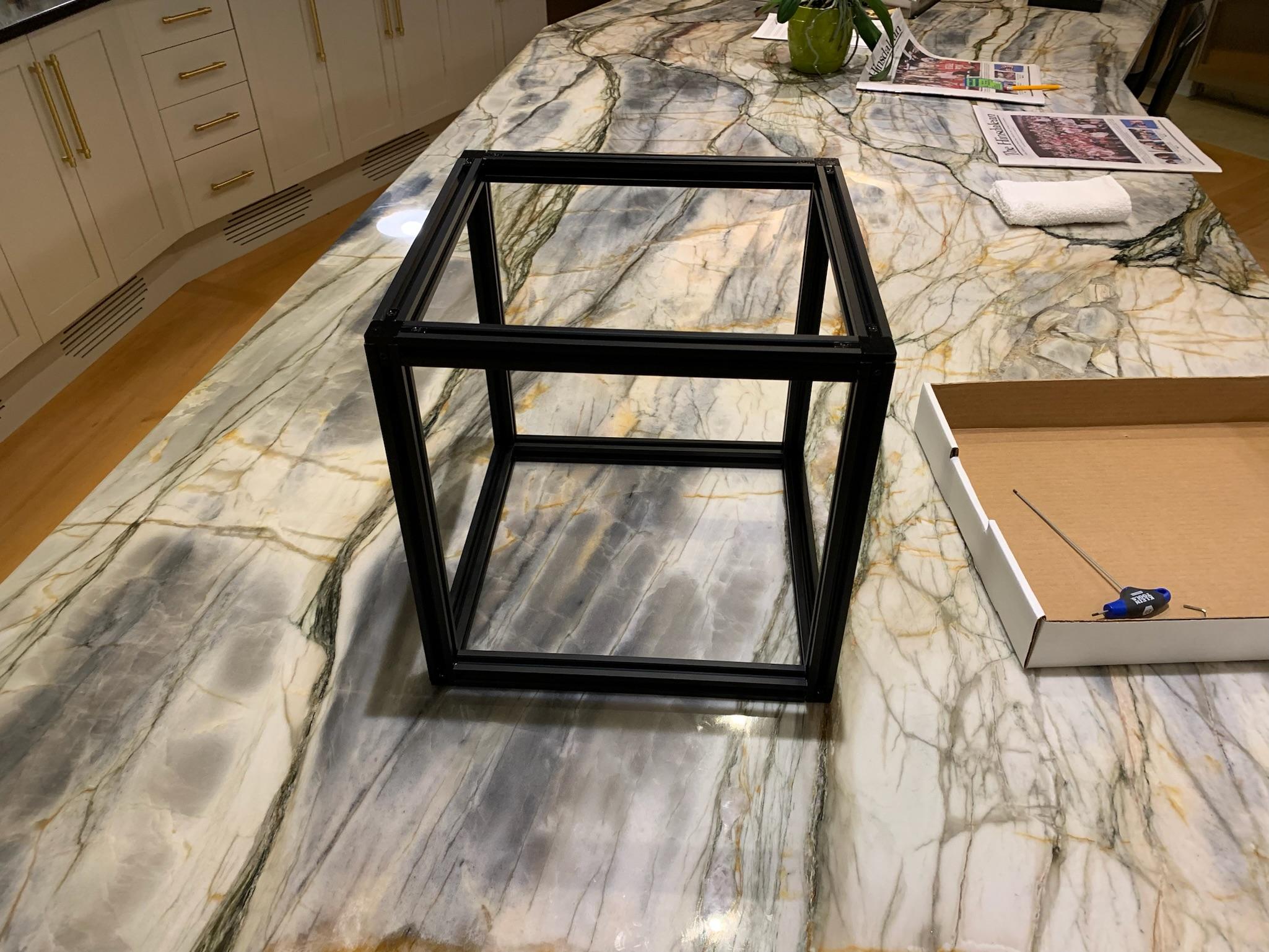
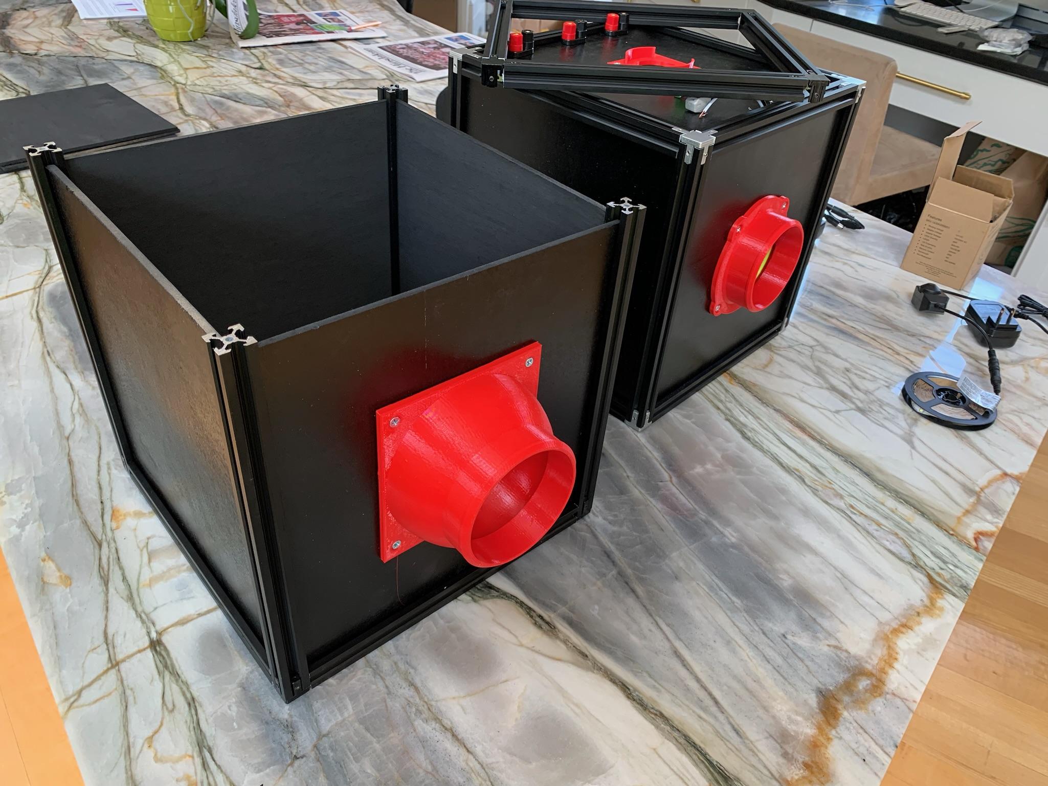
The Dark Box
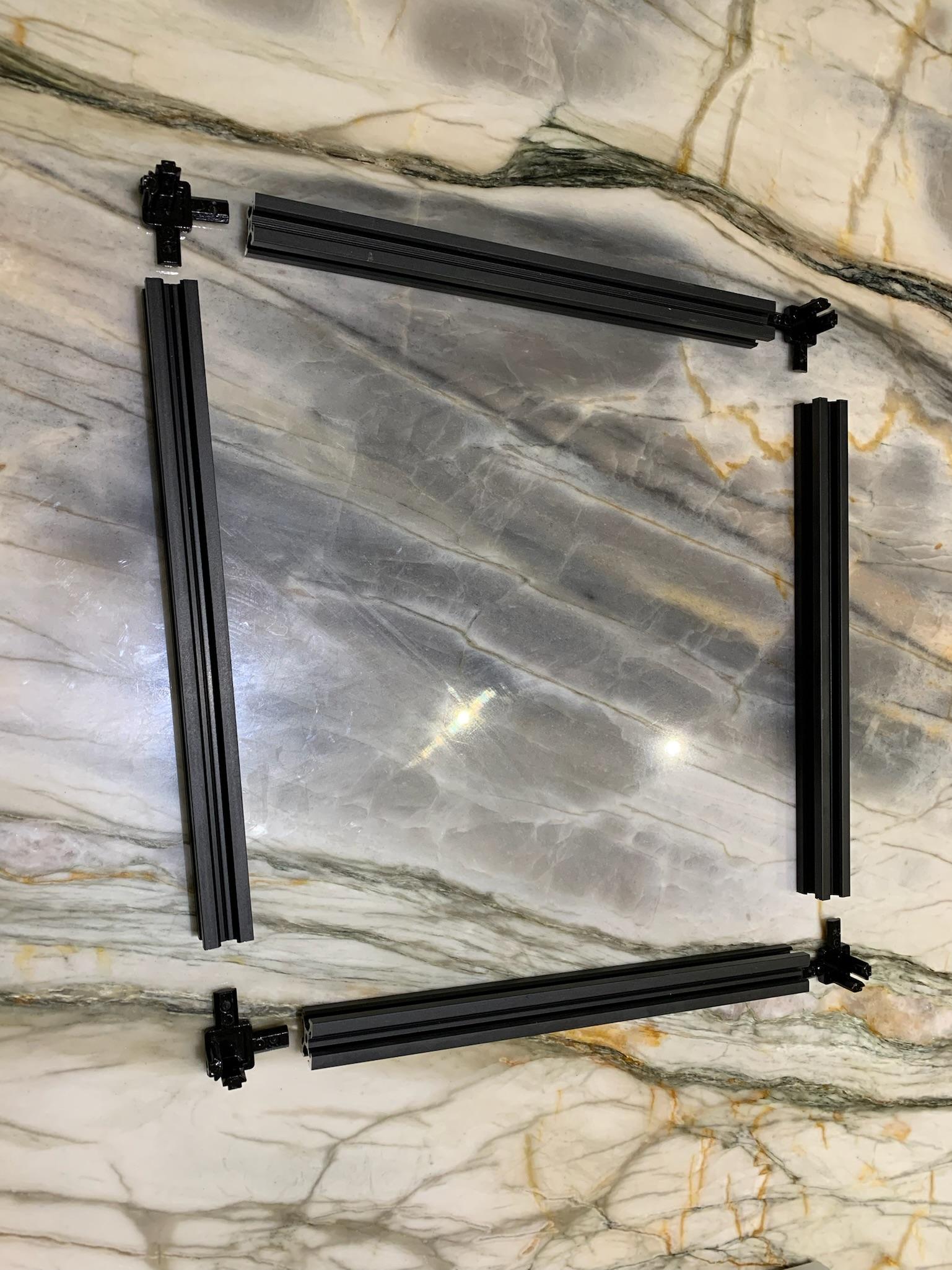
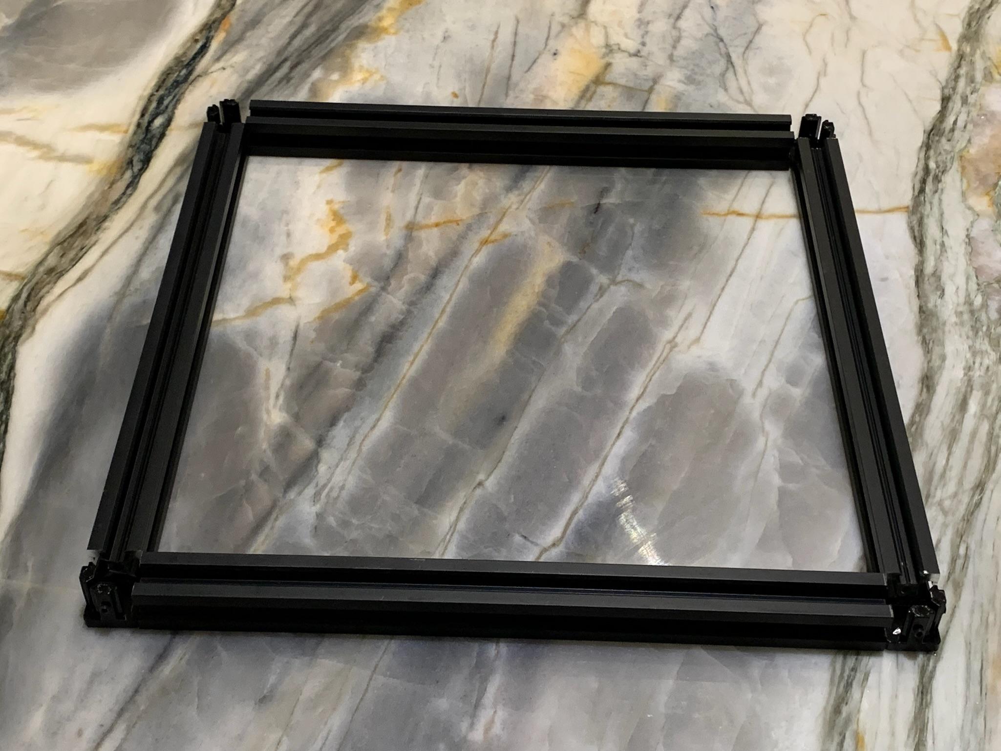
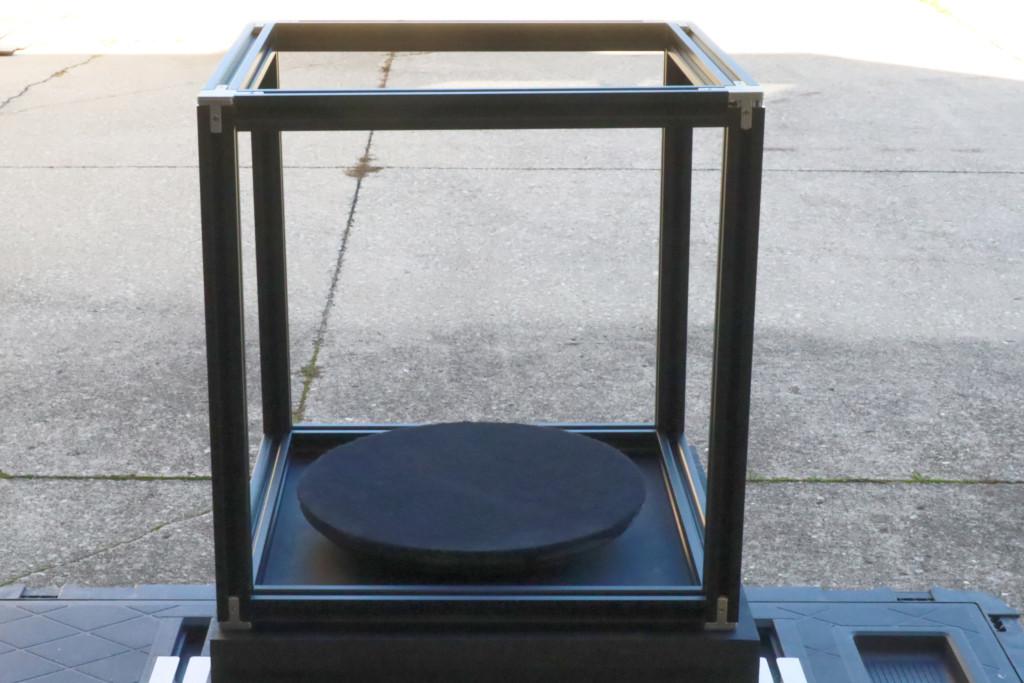
The instructions for constructing the extruded aluminum cube can be found here.
The cube is constructed using black anodized 2020 aluminum extrusions and connectors. We have done everything possible to use dark nonreflective surfaces in the visible and UV spectrum. (Side note, while the anodized extrusion is slightly reflective in the UV spectrum, it was shipped covered in plastic tape to protect the surfaces. The adhesive was mildly fluorescent. We had to scrub it off. )
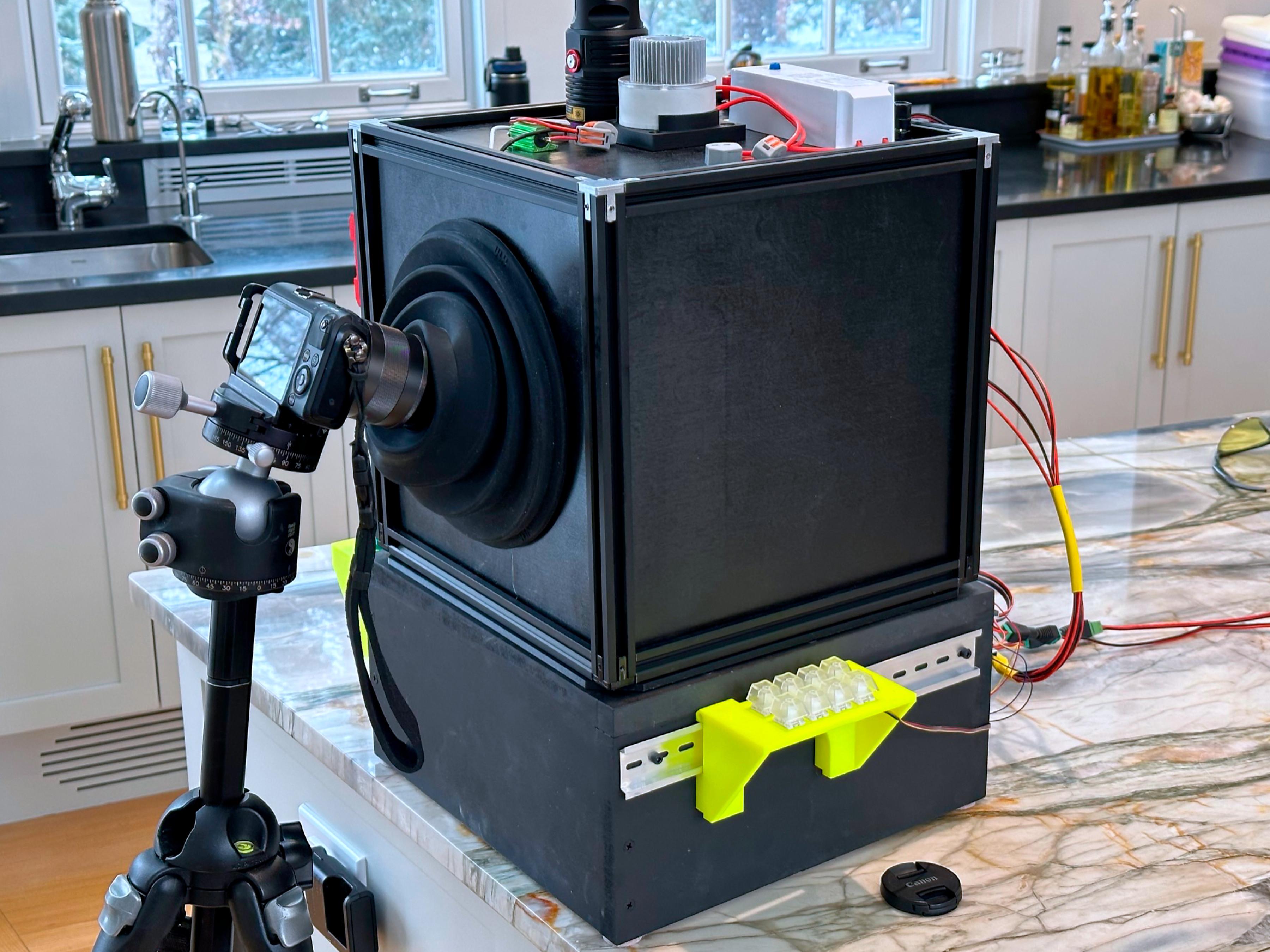
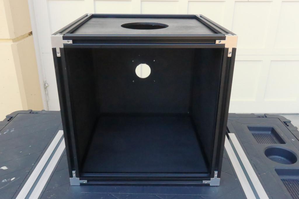
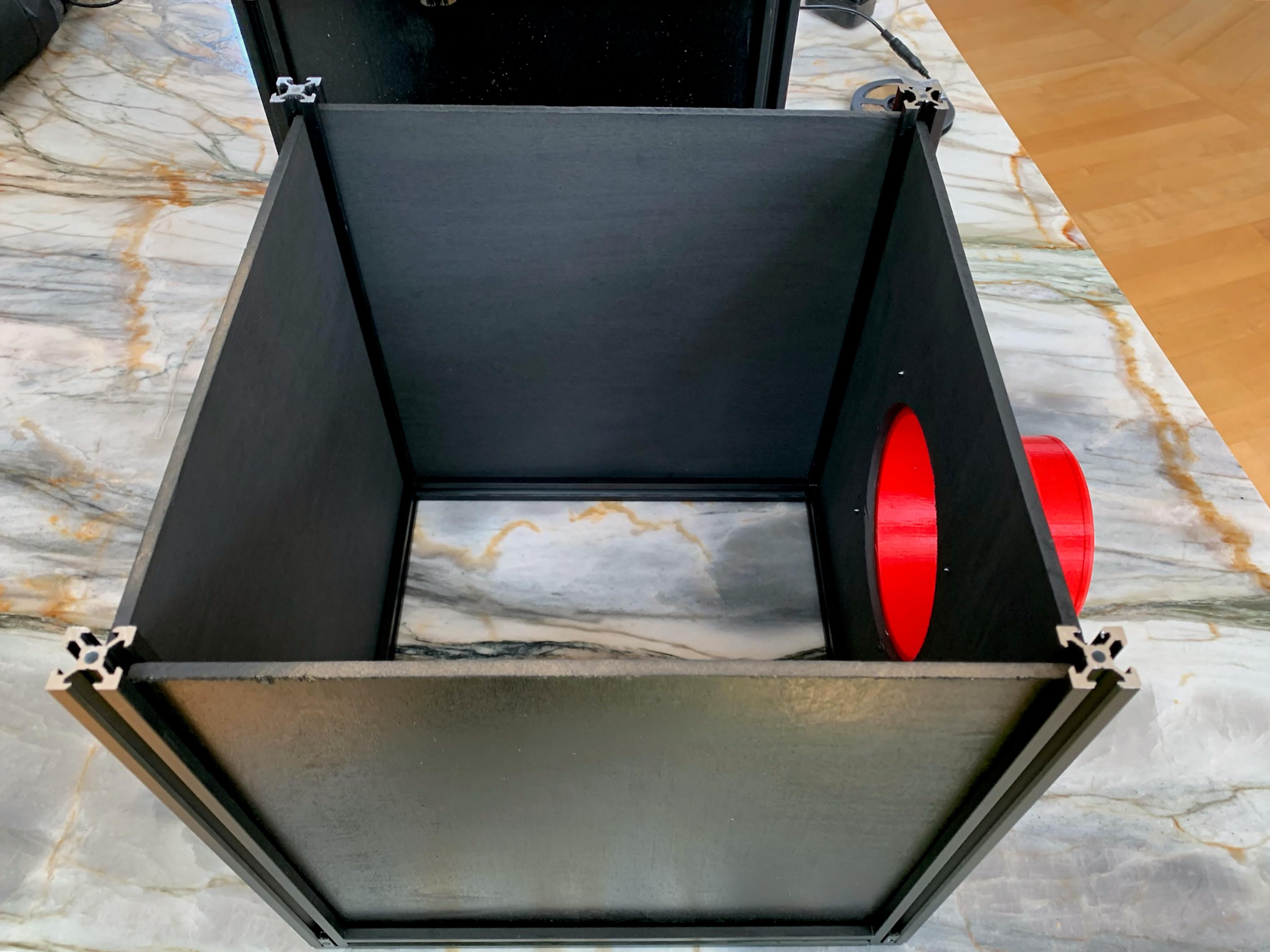
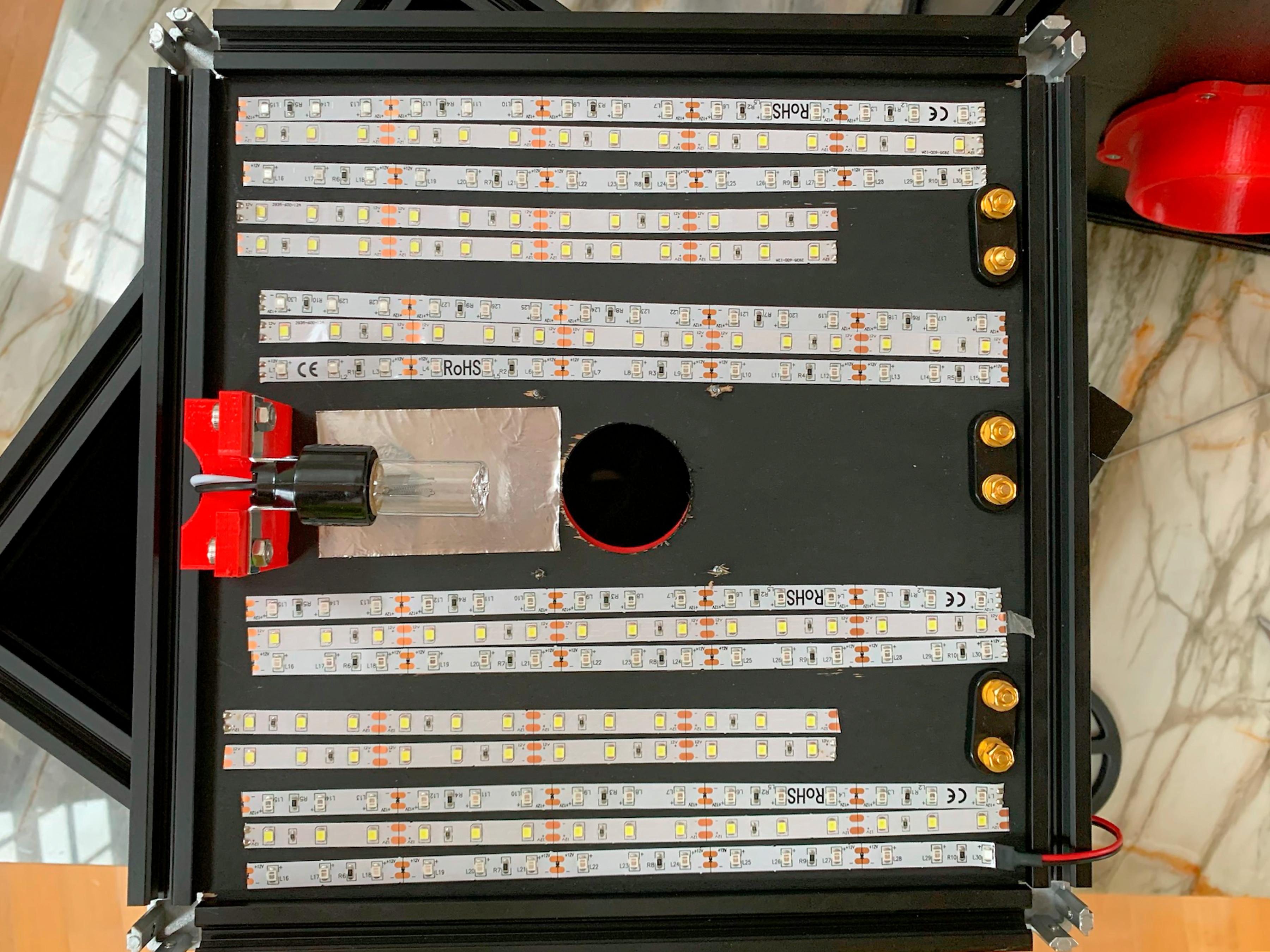
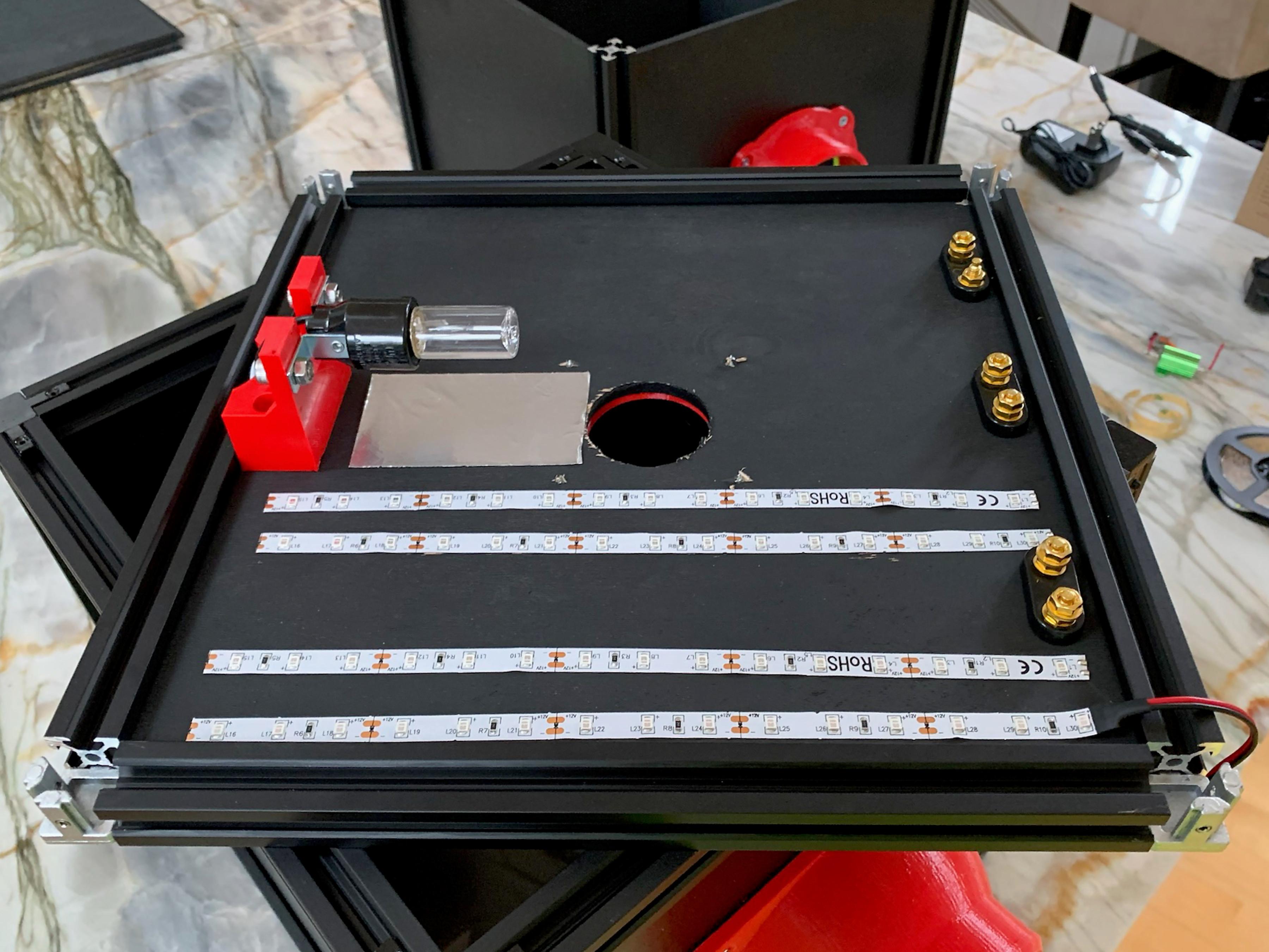
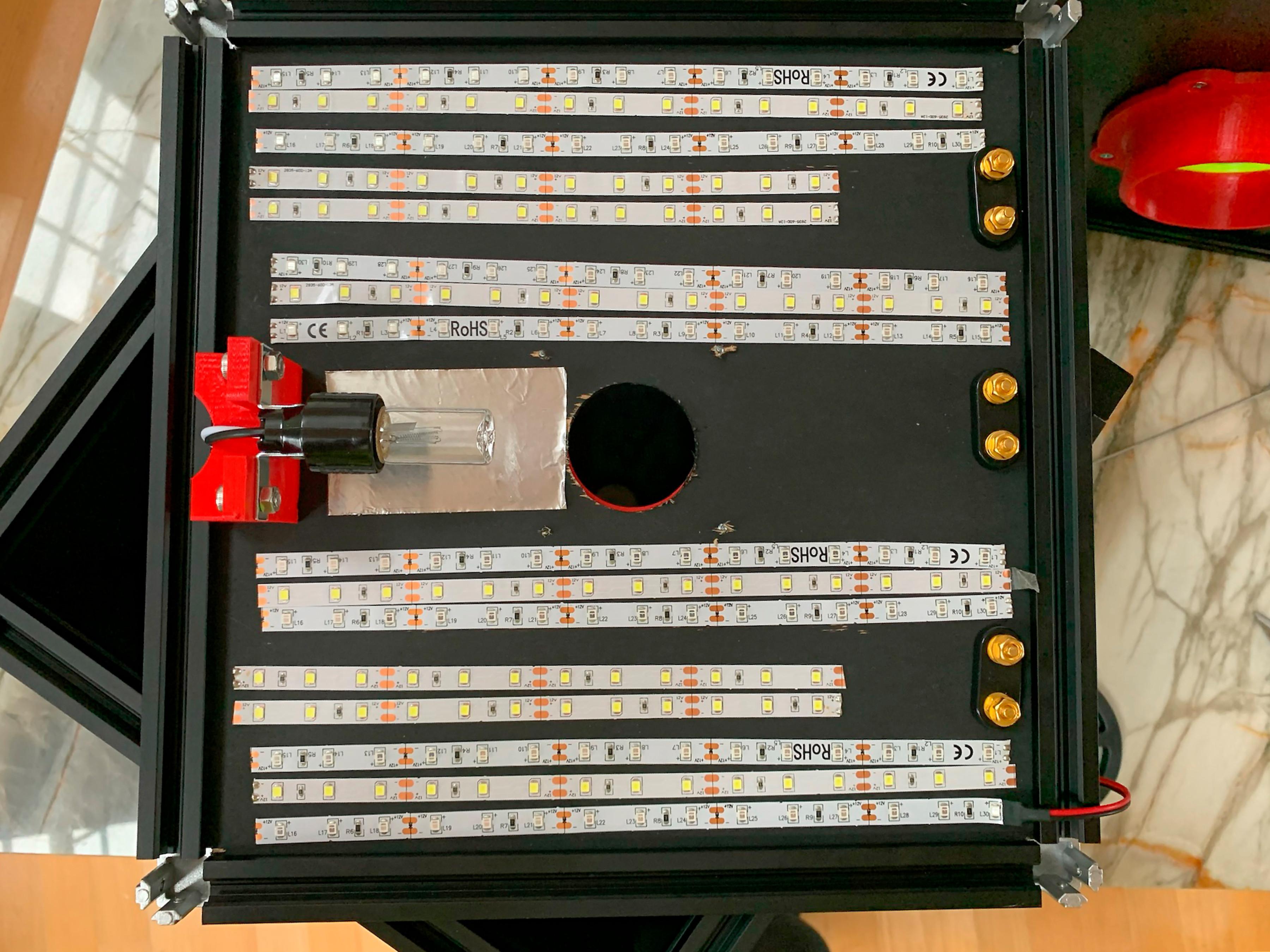
The dark box was enclosed on five sides with panels made of plywood. The panels were painted flat black on the inside and glossy black on the outside. The top panel corners were notched to fit into corners of the aluminum extrusion and had several holes cut into them to provide access to light sources and power connectors.
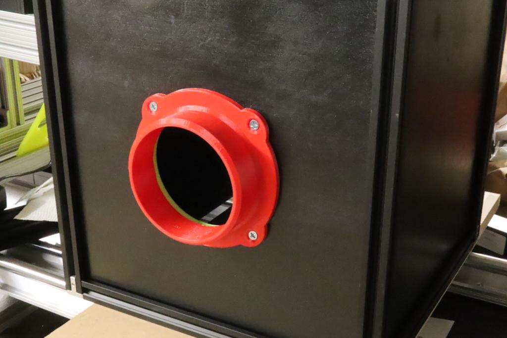
One of the side panels had a hole cut into it for camera access.
The top panel is notched on the corners to provide clearance for the aluminum extrusions. It has several holes cut into it to provide power to light sources mounted to the underside of the panel. There is also a hole cut into the center of the top to mount a lamp and flashlights externally.
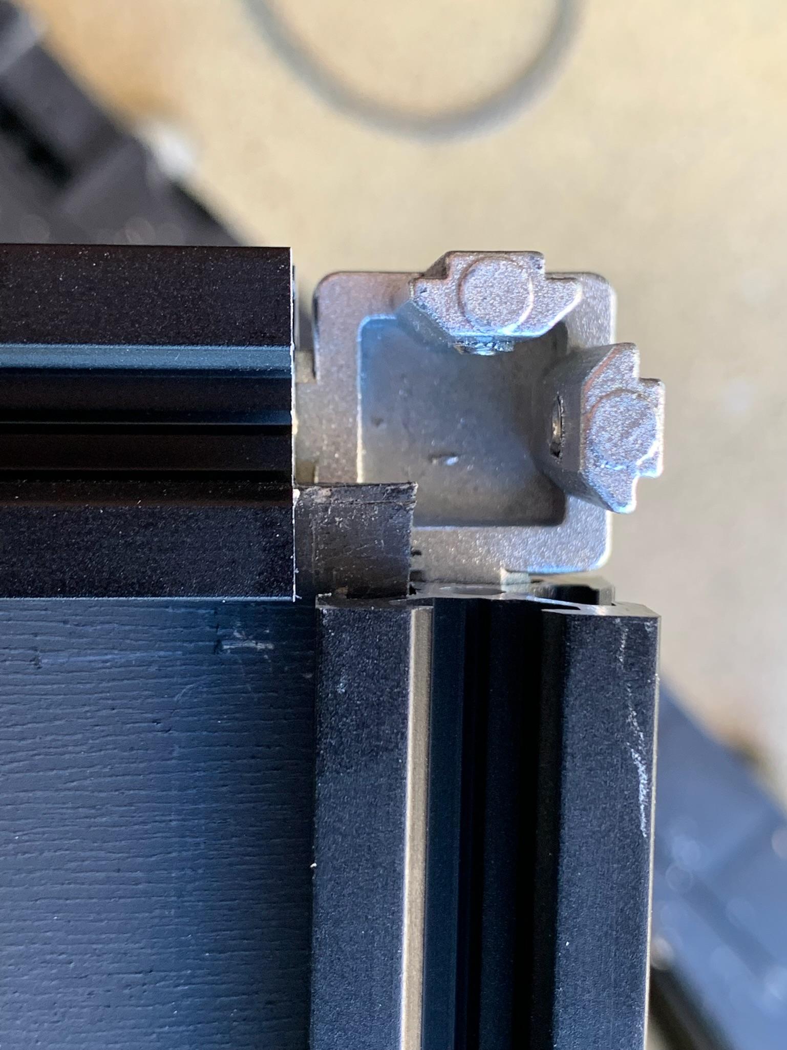
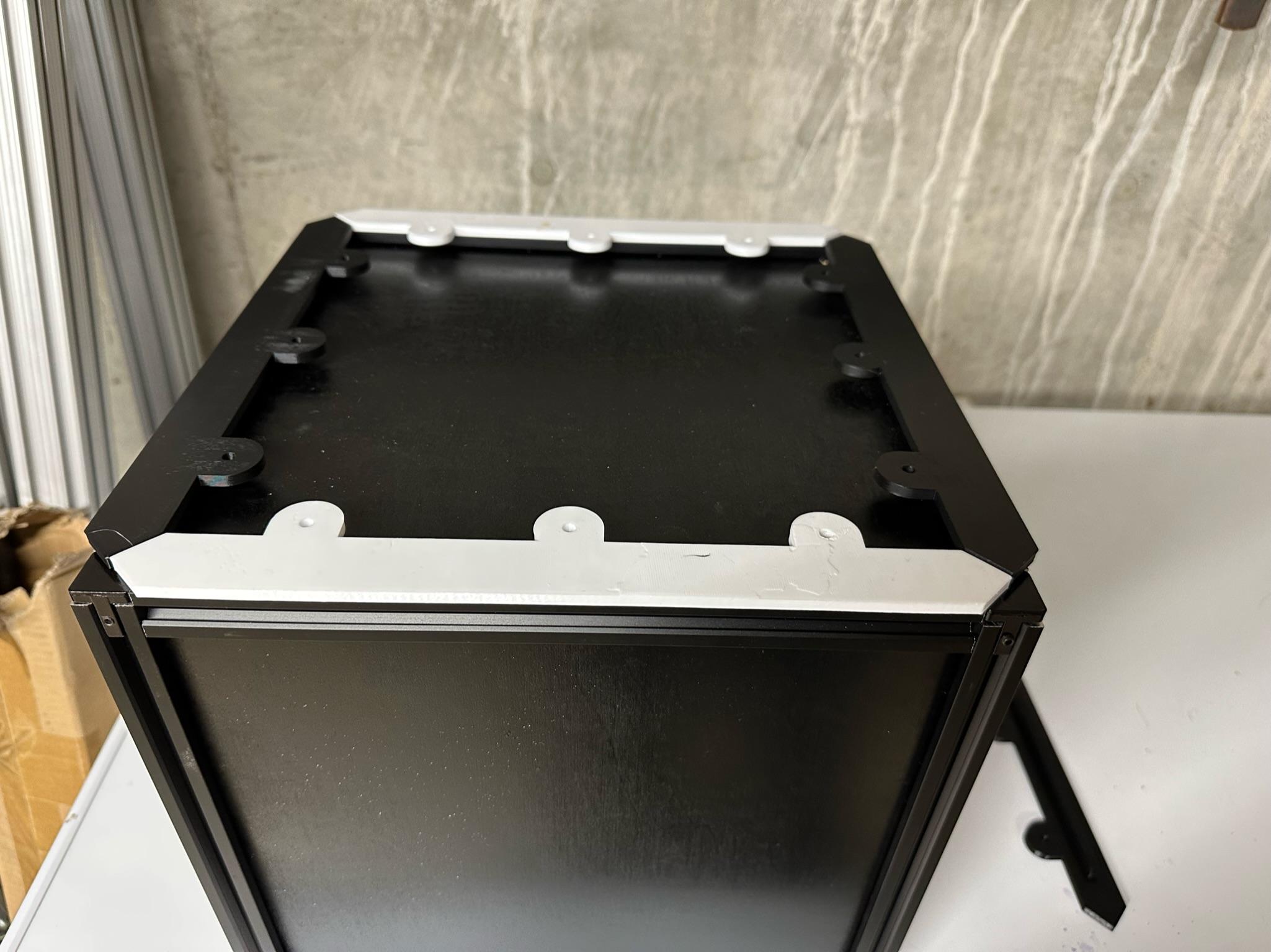
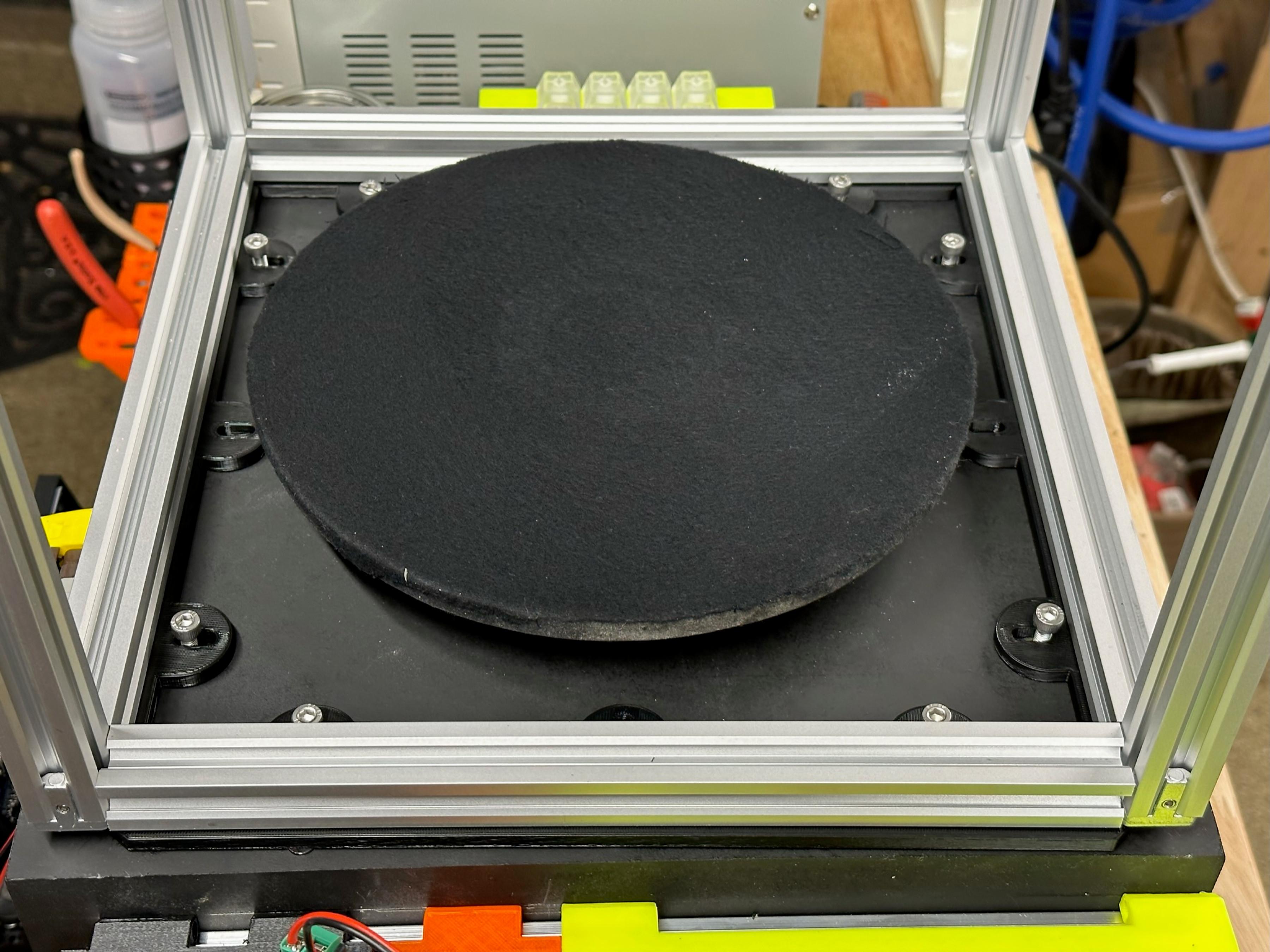
The extruded aluminum cube rested on 3d printed mounts that proved light blocking and alignment on the base.
The base we used had a turntable mechanism built in.
For visibility in the example photos, 3D-printed parts are printed in red or white PLA. The actual production parts were printed in a matte black PLA.
Panels for the Dark Box
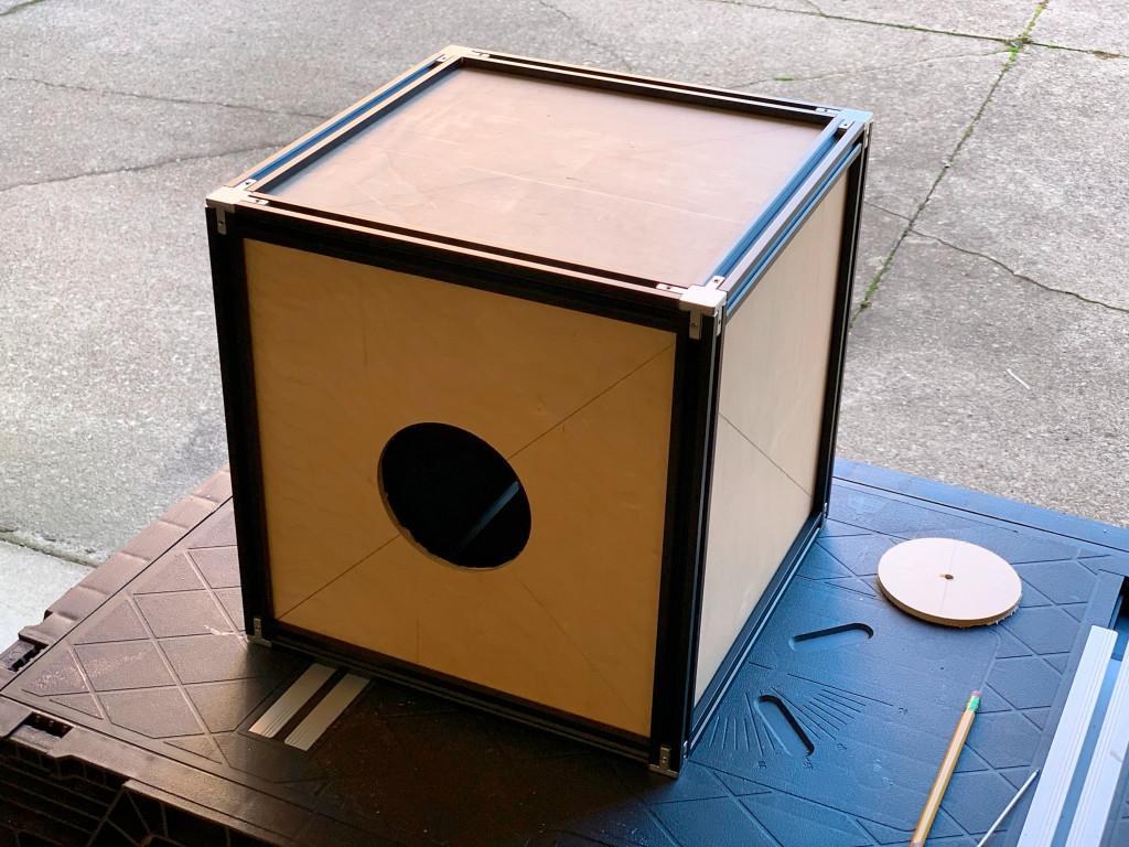
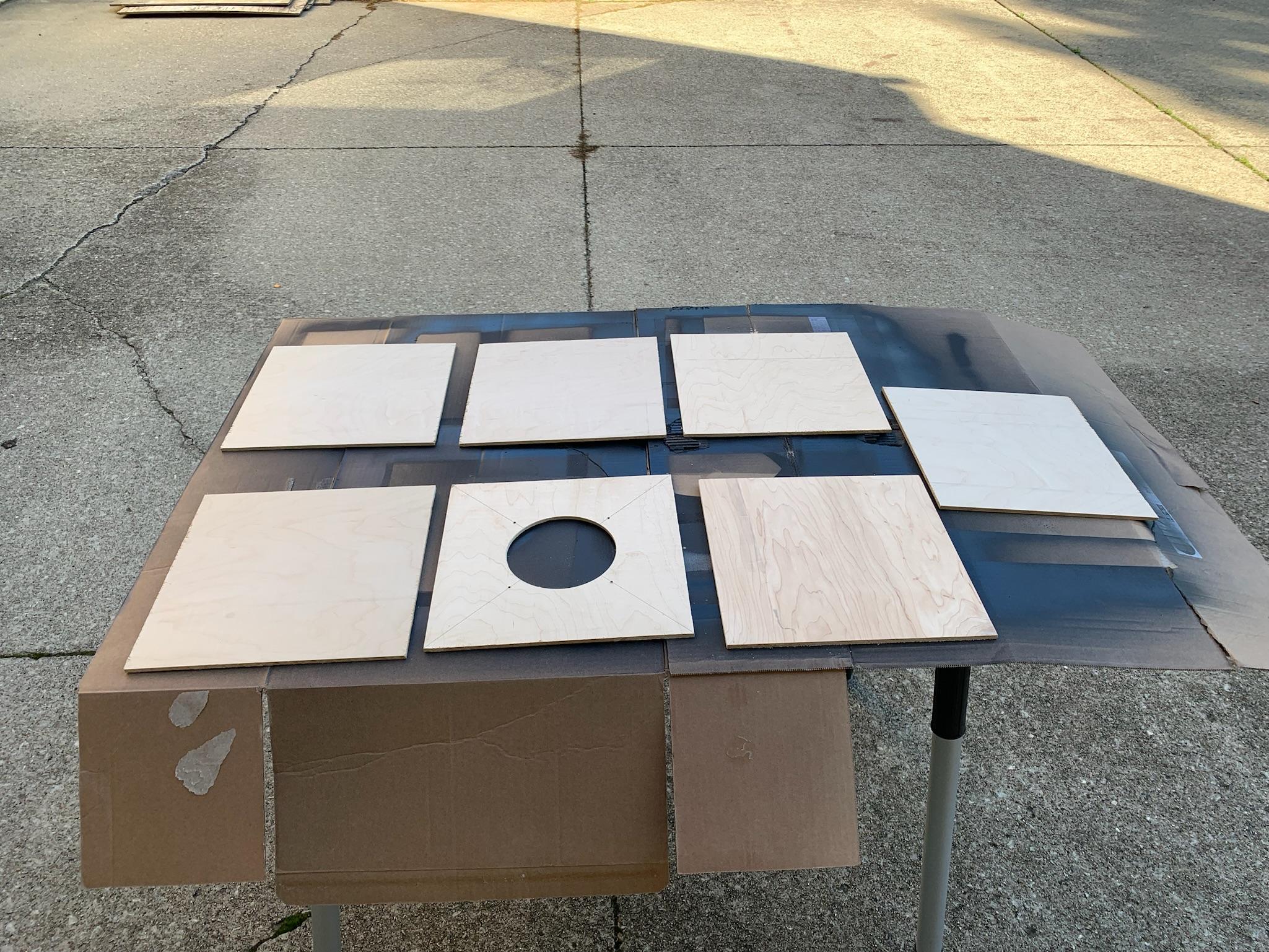
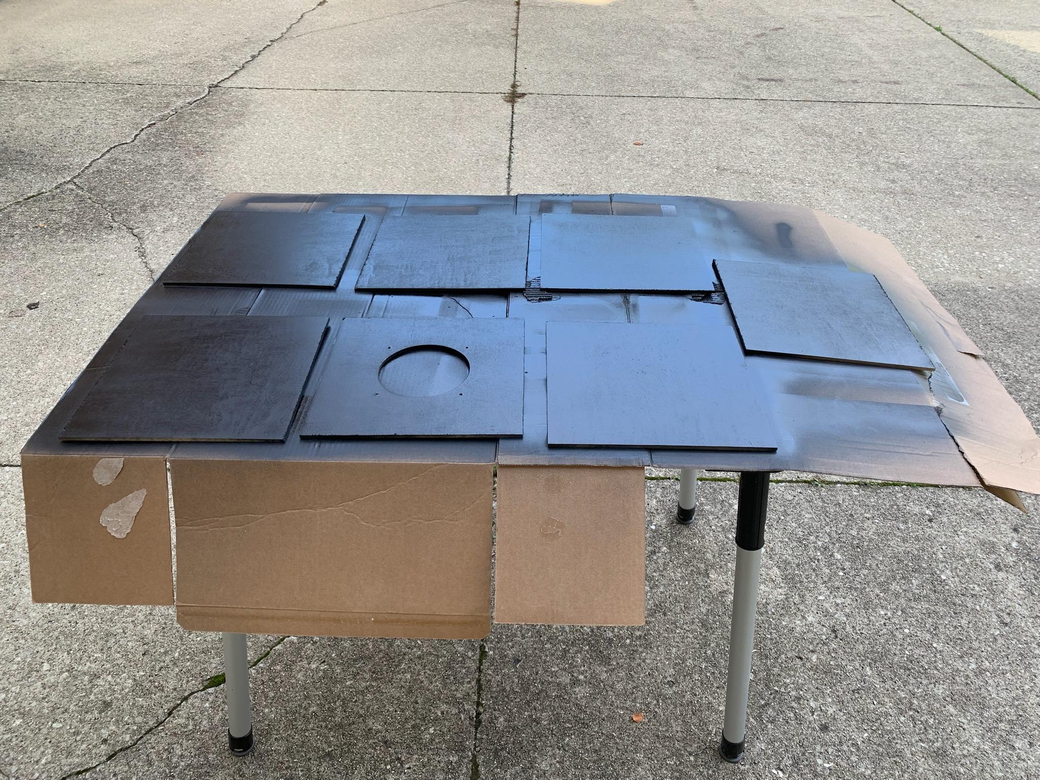
The panels for the dark box were prepared using matte black for the interior surfaces and glossy black for the exterior surfaces. All holes were cut before painting. The top panel was notched after painting.
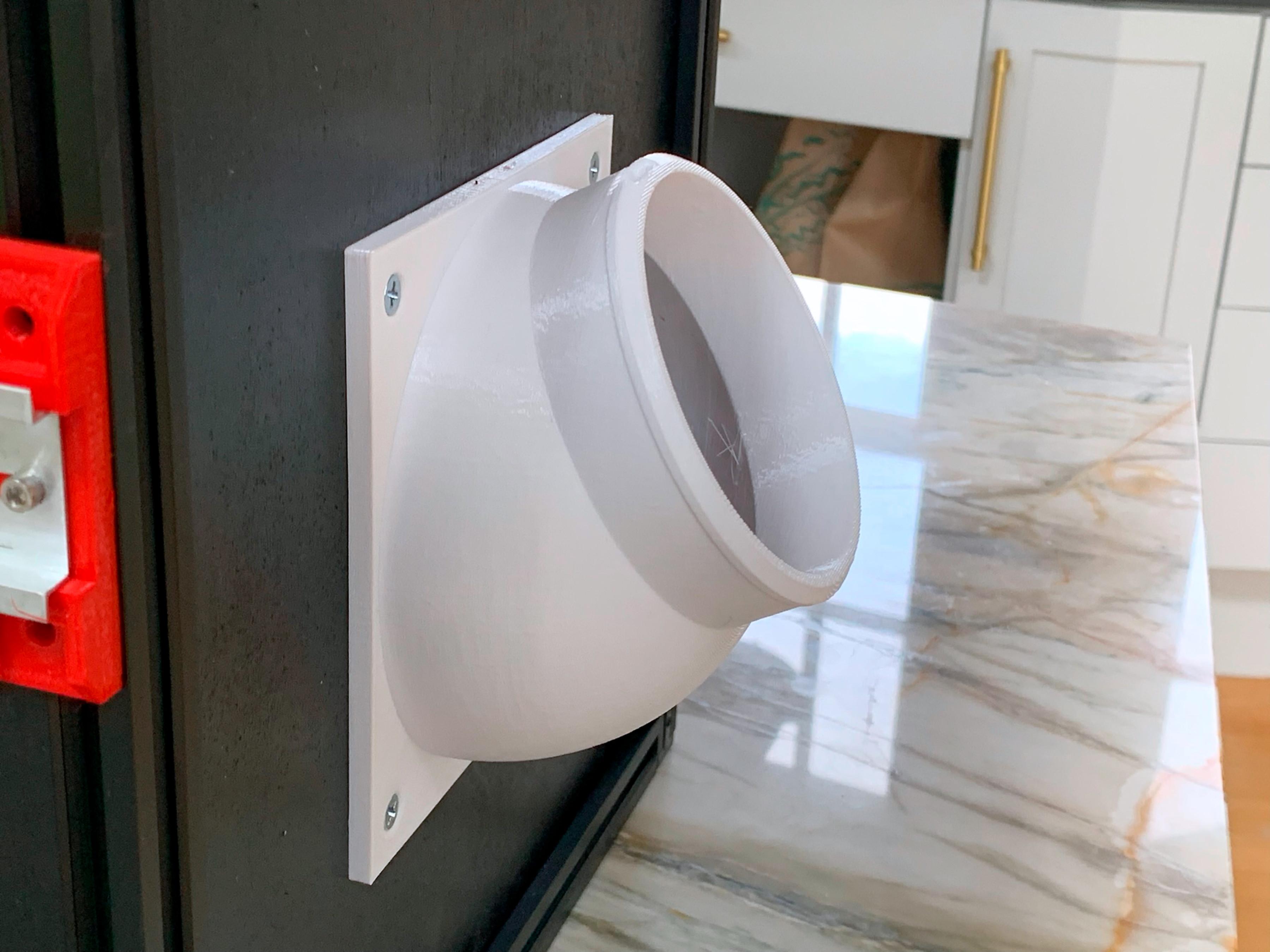
Adding a Bellows
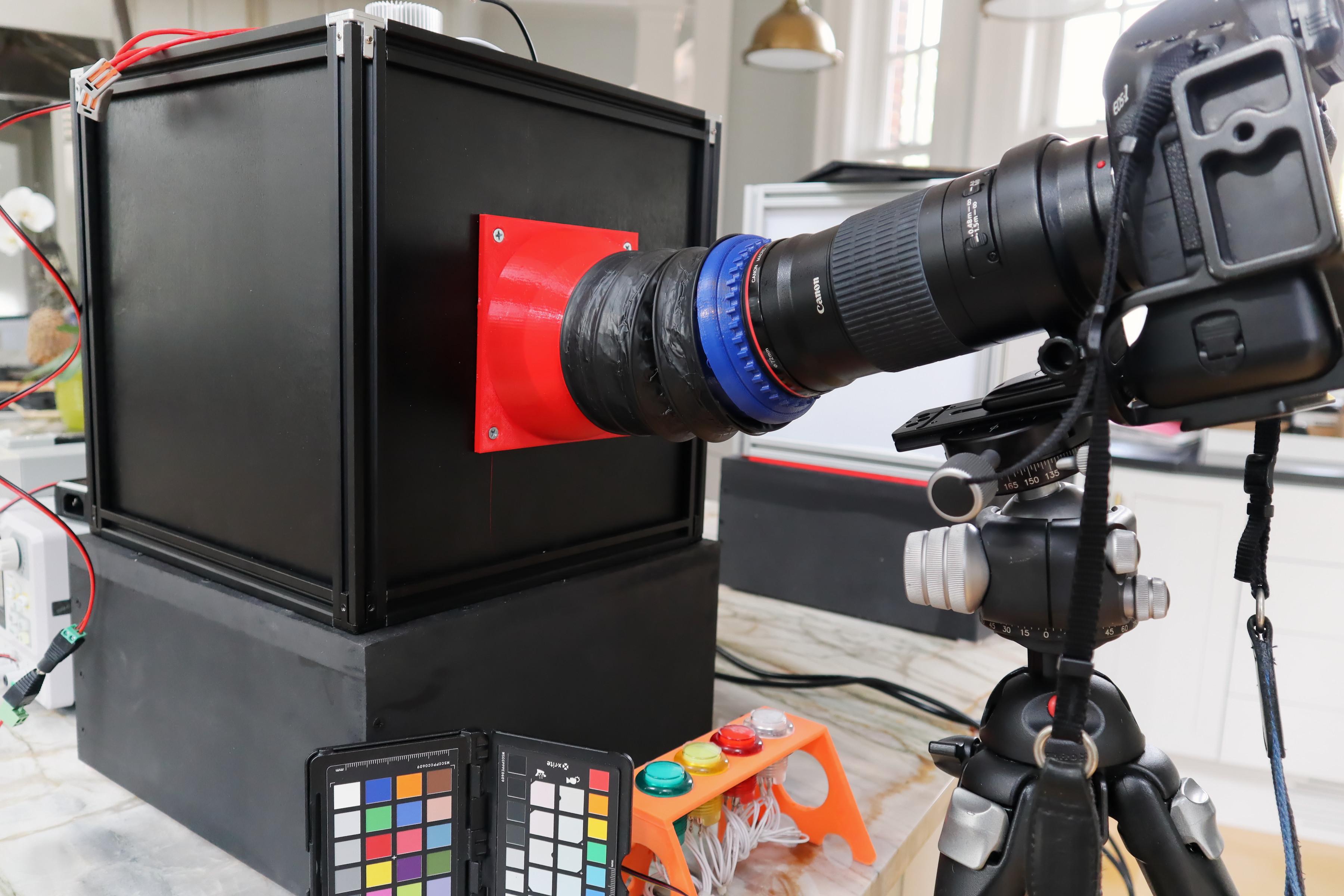
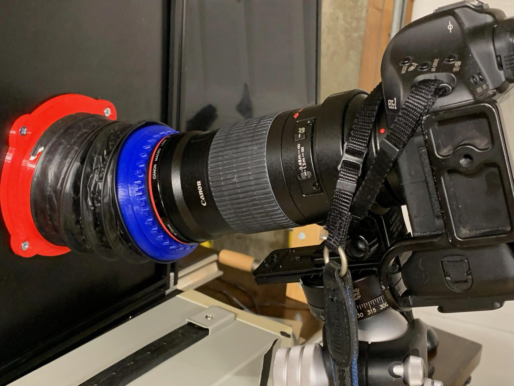
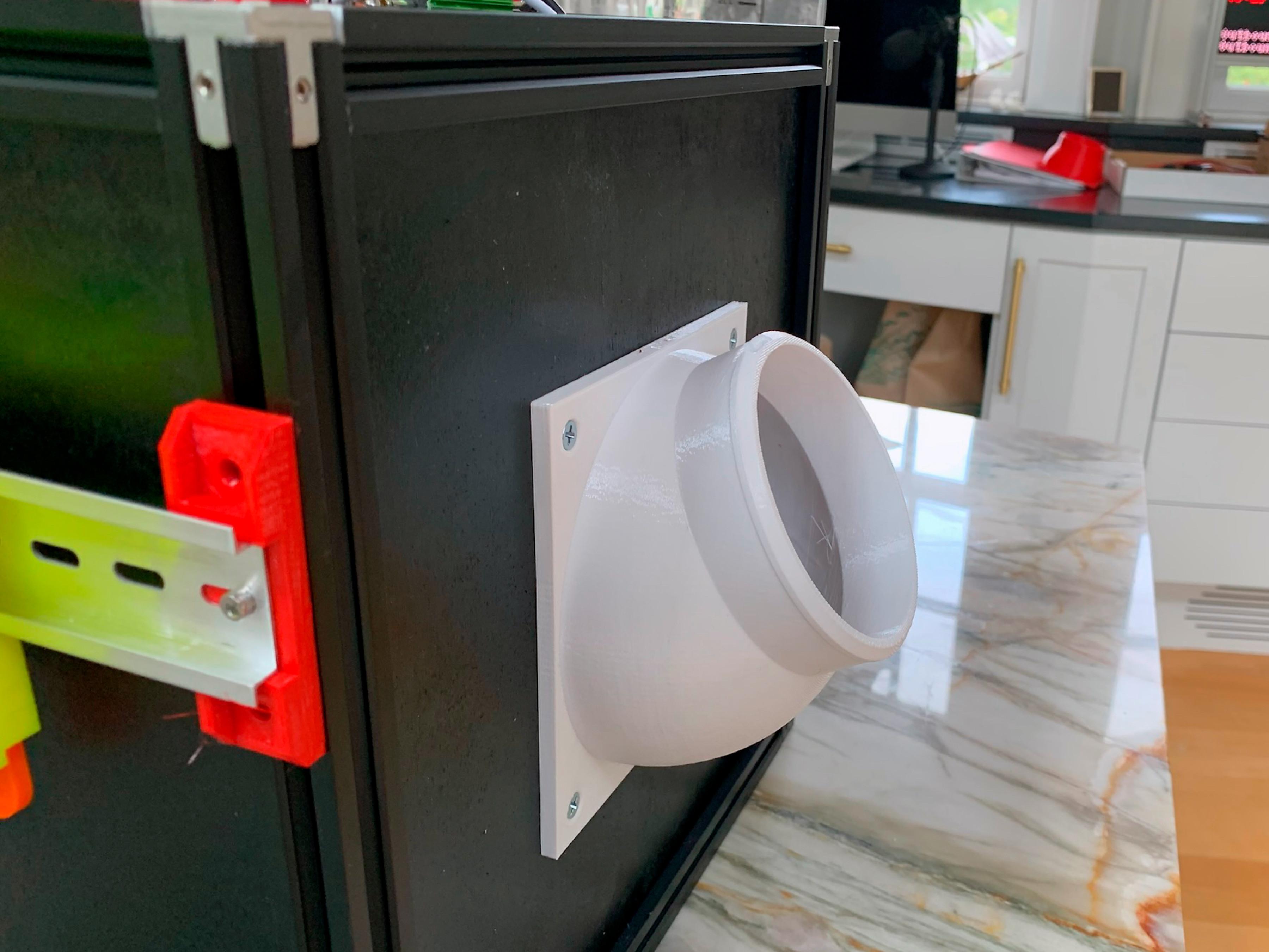
The original approach was constructing a bellows mount lens outside the dark box. This approach works well for zoom and telephoto macro lenses. It has the disadvantage of constructing a bellows mount for each lens. The bellows mount attached to the lens hood threads on each lens. These mounts are not standardized and have to be custom created in Fusion 360.
We have provided a link for the Canon 180mm macro lens we use.
The bellows tube was constructed from a four-inch flexible aluminum duct from Amazon. We cut an 18-inch piece and twisted it onto the end of each mount. When cutting the tube, cut the fabric straight across and then clip the wire.
Straight bellows mount: Printables Thingiverse
Offset bellows mount: Printables Thingiverse
Adapter for a Canon 180mm macro lens: Printables Thingiverse
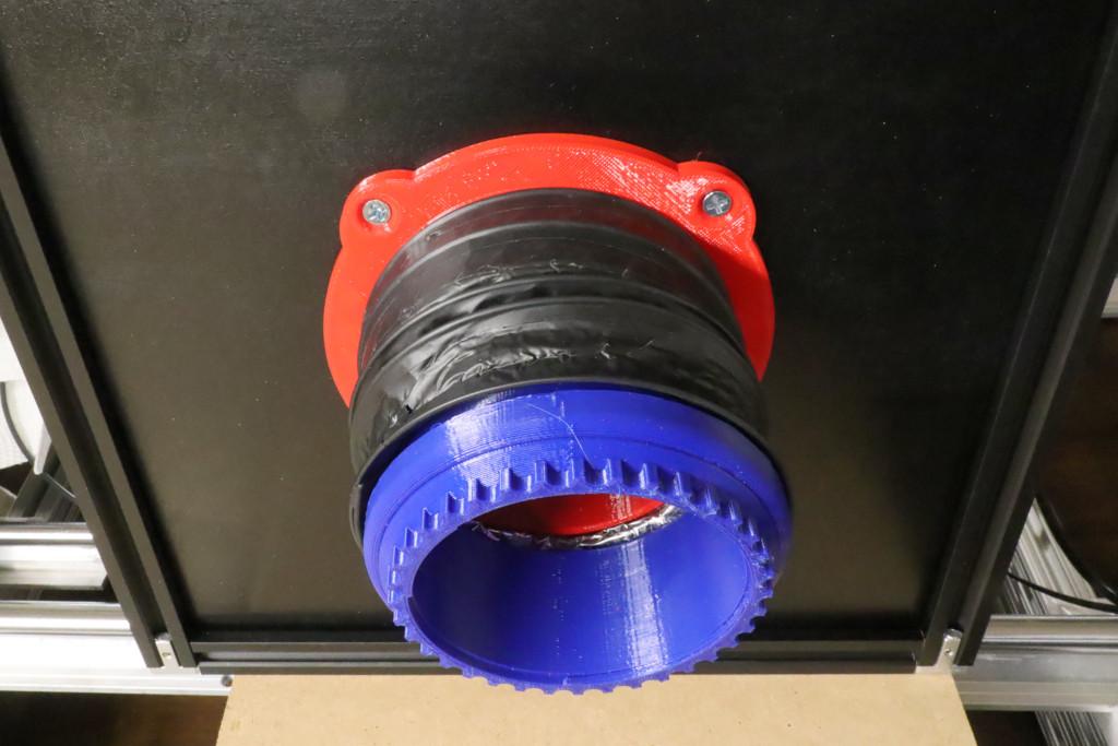
Addin a Bellows an Alternate Approach
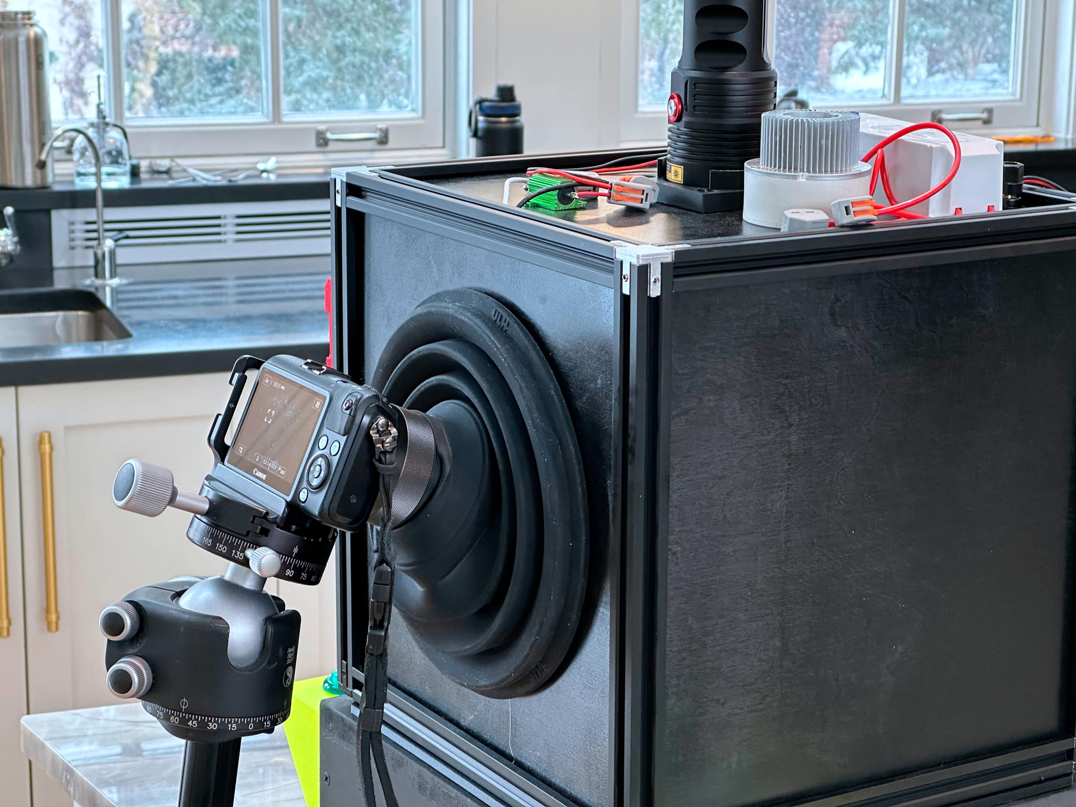
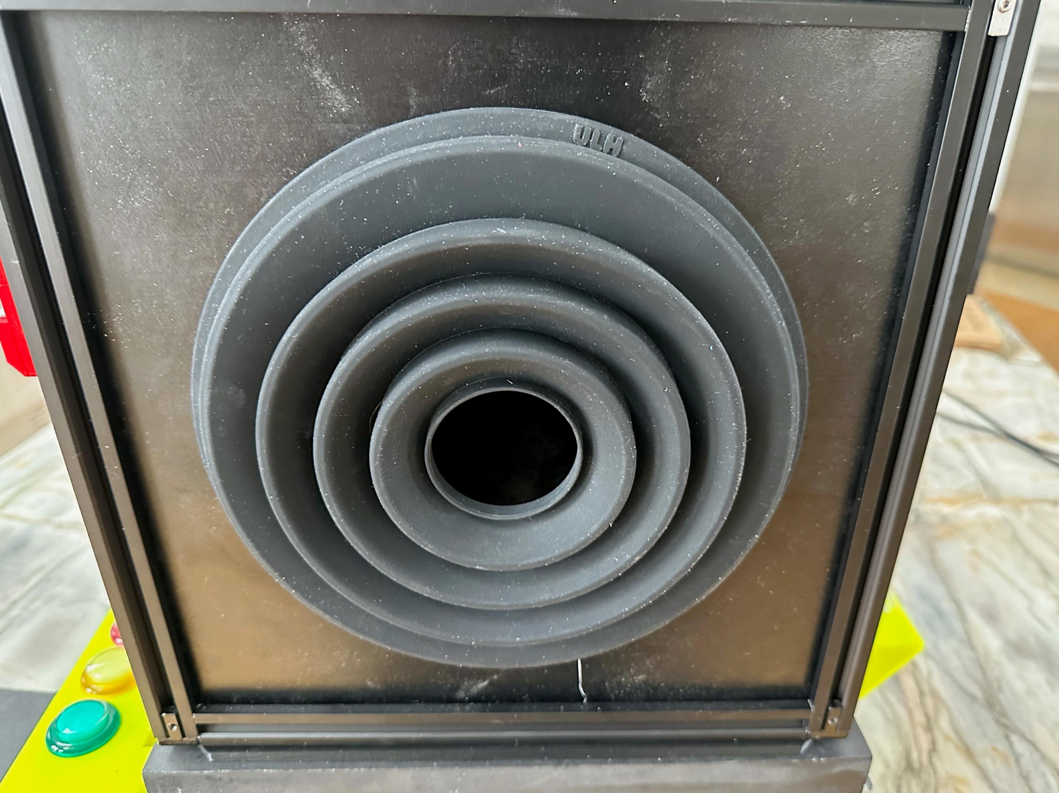
An alternate bellow can be constructed using a ULHgo lens hood and a 3d printed retaining ring. This configuration works best with a wide-angle lens.
To use this system:
- Place the hood on the lens.
- Place the camera on the tripod.
- Adjust the tripod so that the camera and hood are the same height as the bellows mounting ring.
- Do a rough framing and focus of the image.
- Attach the hood to the mounting ring.
- Set your lighting
- Do your final focus, and take your pictures.
You will have some play in the hood to adjust your image, or if there are multiple samples, move to the next one.
ULHgo bellows mount: Printables Thingiverse.
The ULG-go can be found here.
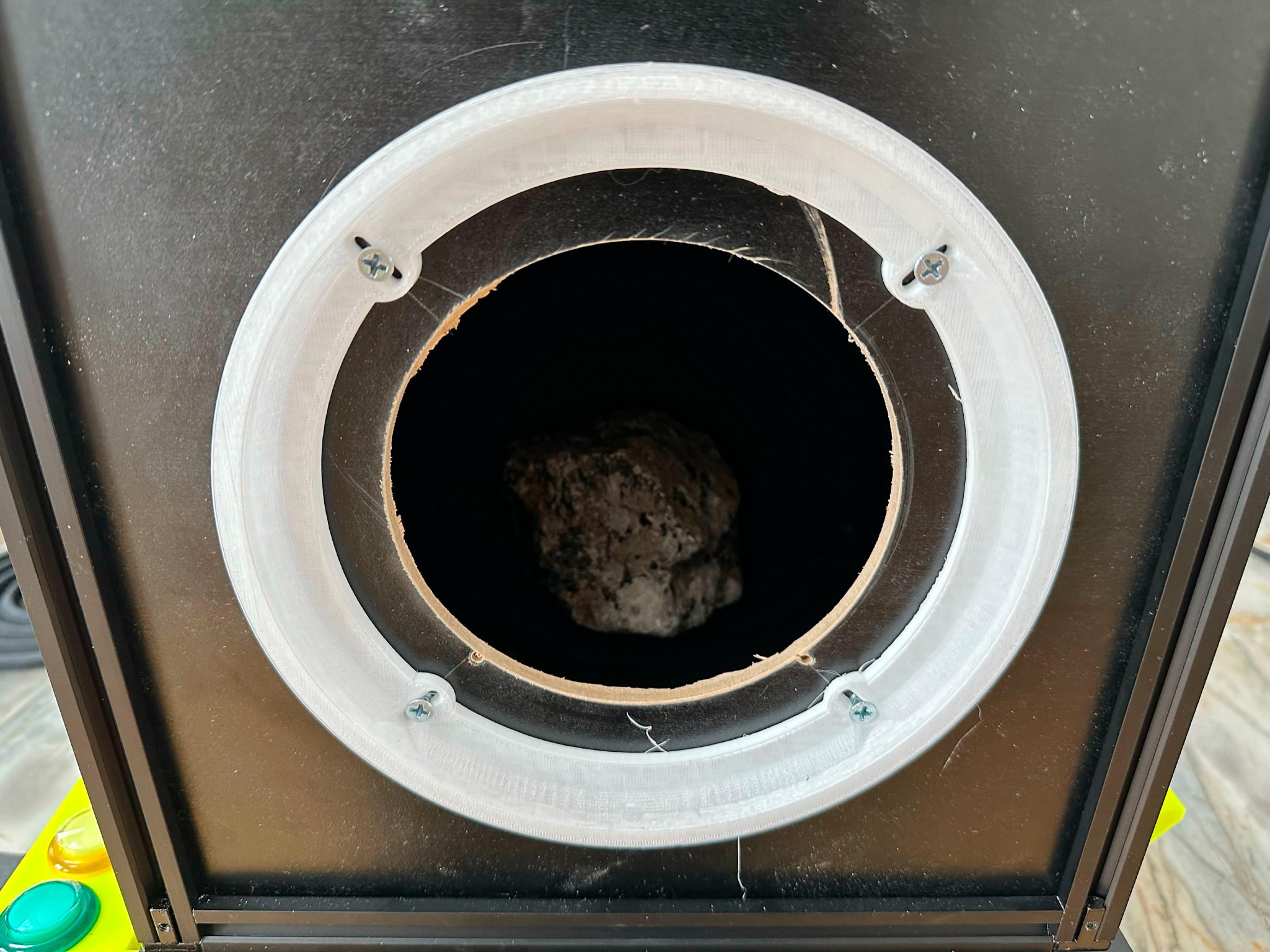
We made two panels, one for the bellows and one for the ULHgo hood. We swap them out as needed.
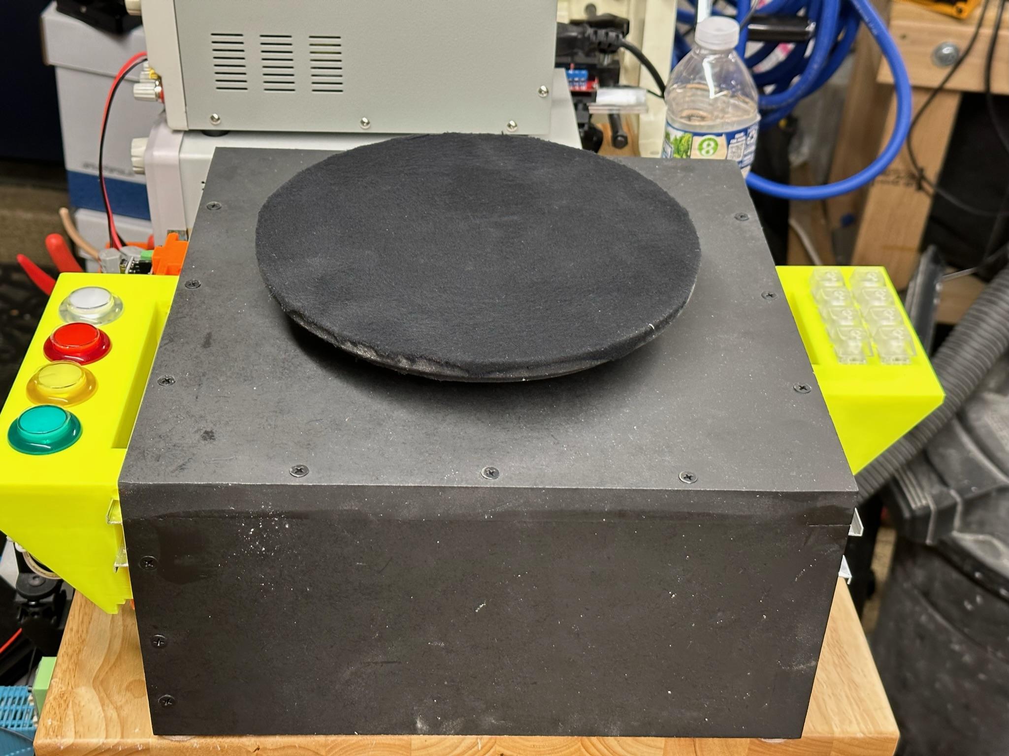
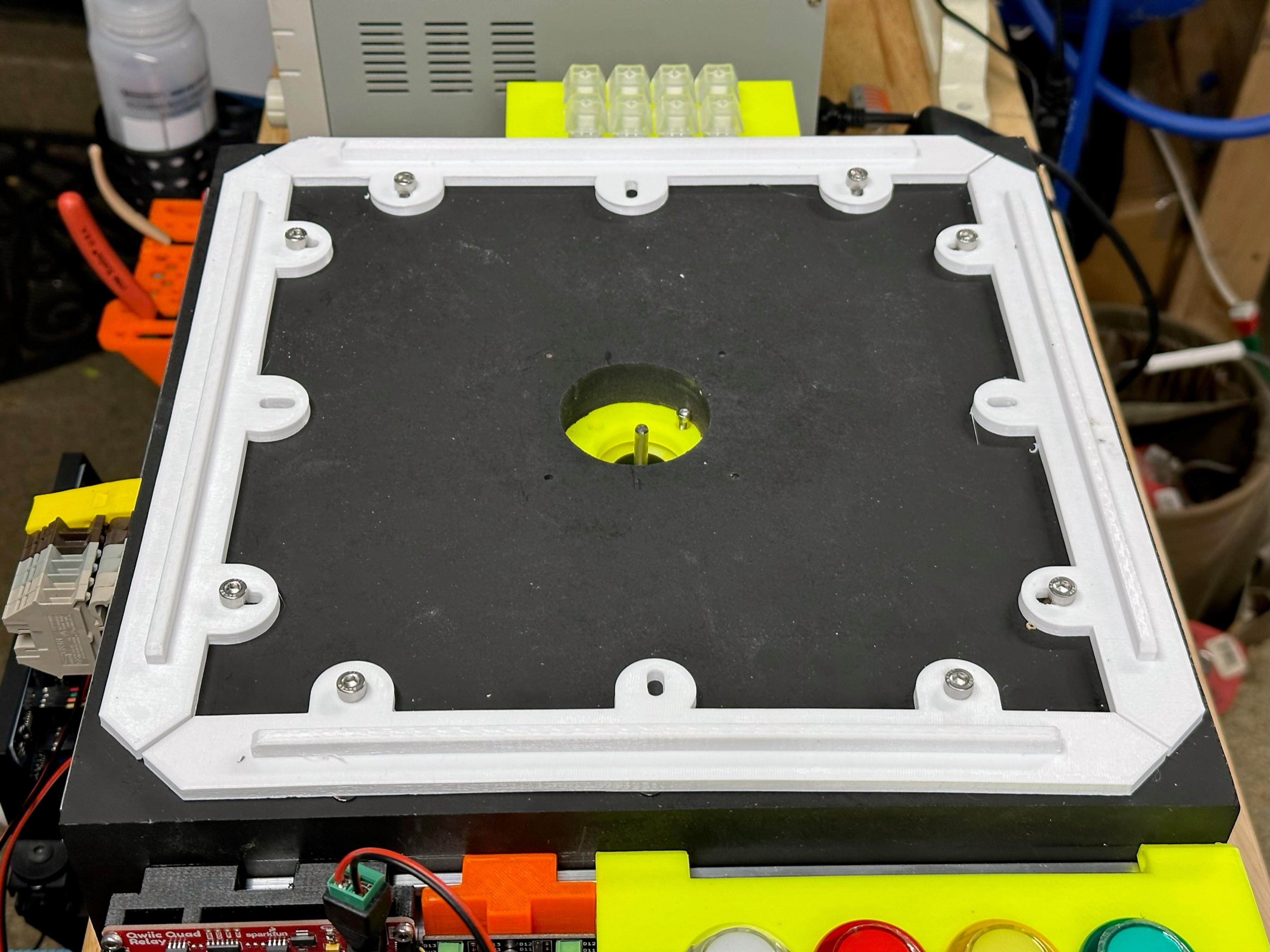
Choose a Base
The primary reason to have a base is to prevent light leaks in and out of the dark box.
The simplest form of a base is to place the dark box on a couple of layers of heavy black felt. Alternatively, use the 3dprinted mounting rails attached to a piece of MDF or plywood that you have painted flat black.
We used a base that incorporated a turntable to adjust the samples without continually opening the box. This is a "nice to have," not a requirement. It makes shooting a lot more productive. The design can be found here.
The designs for the 3d printed mounting rails can be found here:
2020: Printables Thingiverse
8020 series 10: Printables Thingiverse
Printables Thingiverse
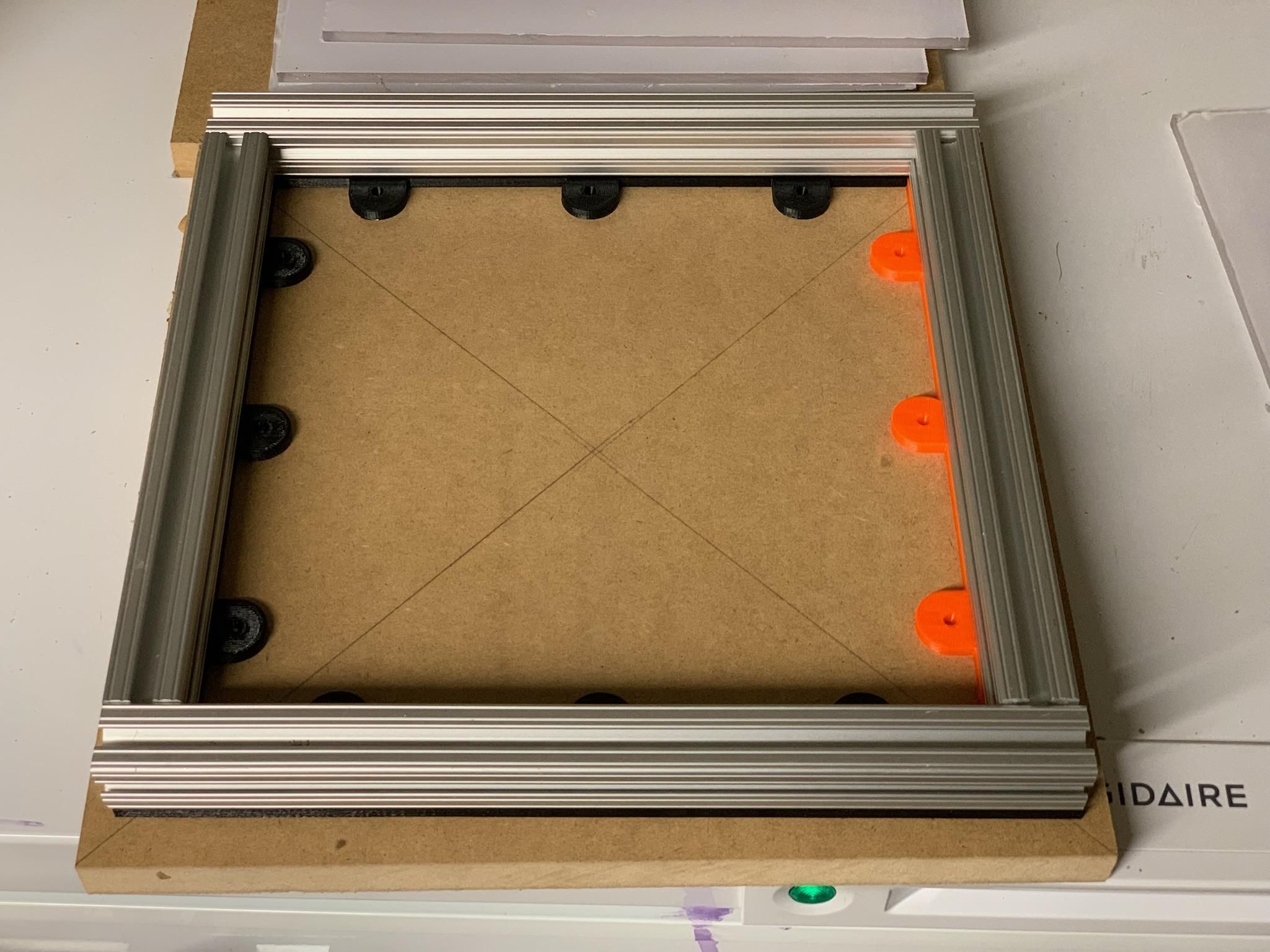
Modifications to the Base Part 1
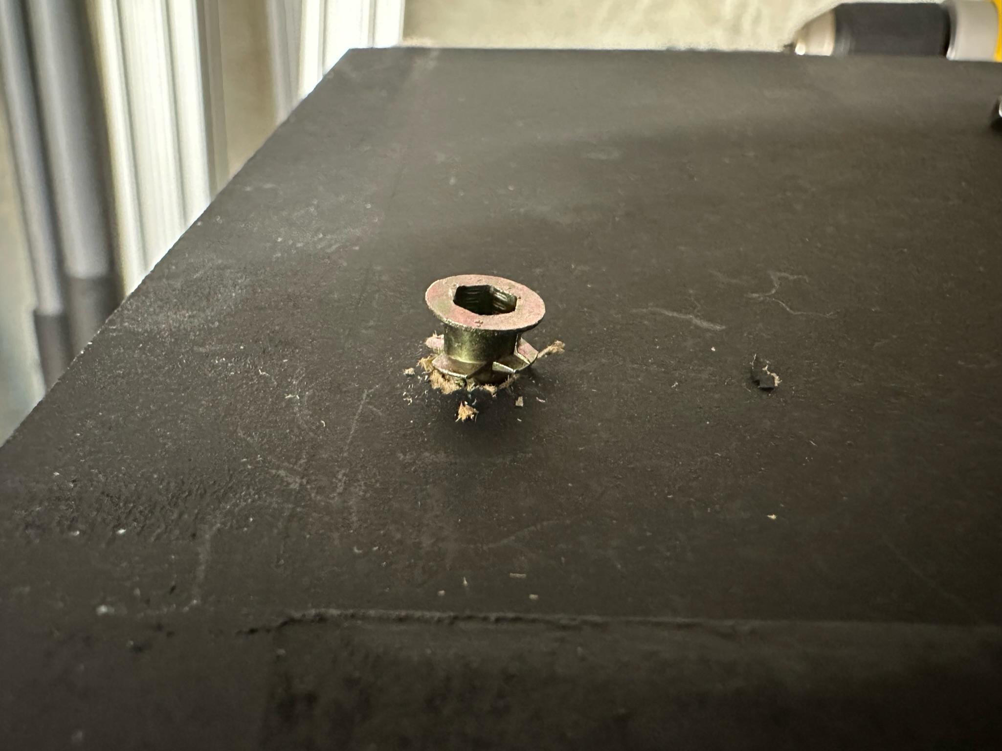
We made two changes to the base described in "A-Simple-Rotating-Stage-for-Photography-or-Display." We wanted any change we made to have minimal impact on the original project and to be undoable.
This change and the subsequent change were accomplished by adding wood inserts.
The inserts we used can be found here.
- First, match the insert to the screw you will be using.
- Pick the right size drill bit if one did not come with the kit.
- Mark your hole locations. In our case, we removed the bottom of the dark box's aluminum extrusion so we had a frame. We then inserted the 3D-printed guide rails and positioned this on the top of the base.
- We used the holes in the guide rails to make our drill location marks.
- Drill the holes
- Place an insert in each hole and screw it in.
- Position the item you are attaching over the insert and screw in the appropriate size and style screw. In this case, the guide rails.
If there is a slight gap where the 3D-printed parts meet, fill it in with some dark putty or caulk.
You can remove the guide rails if you want to do a different photo project.
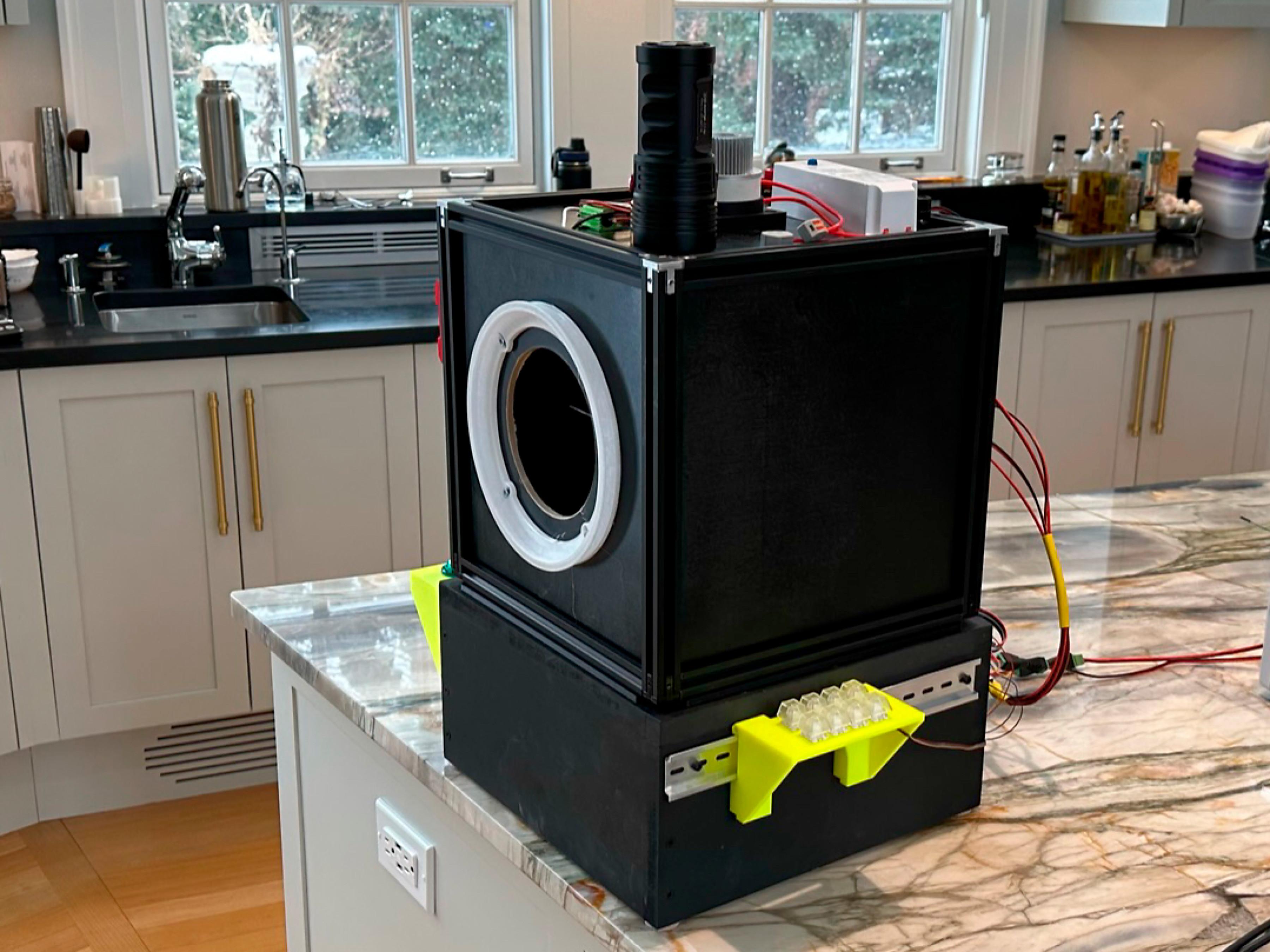
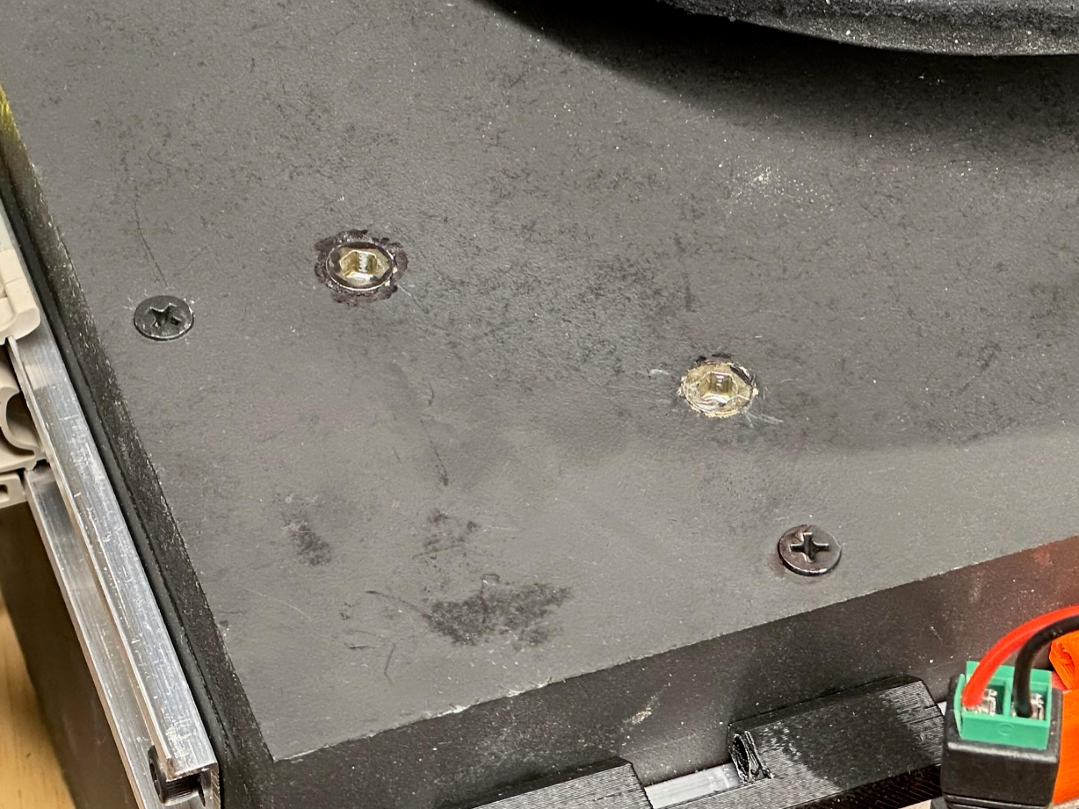
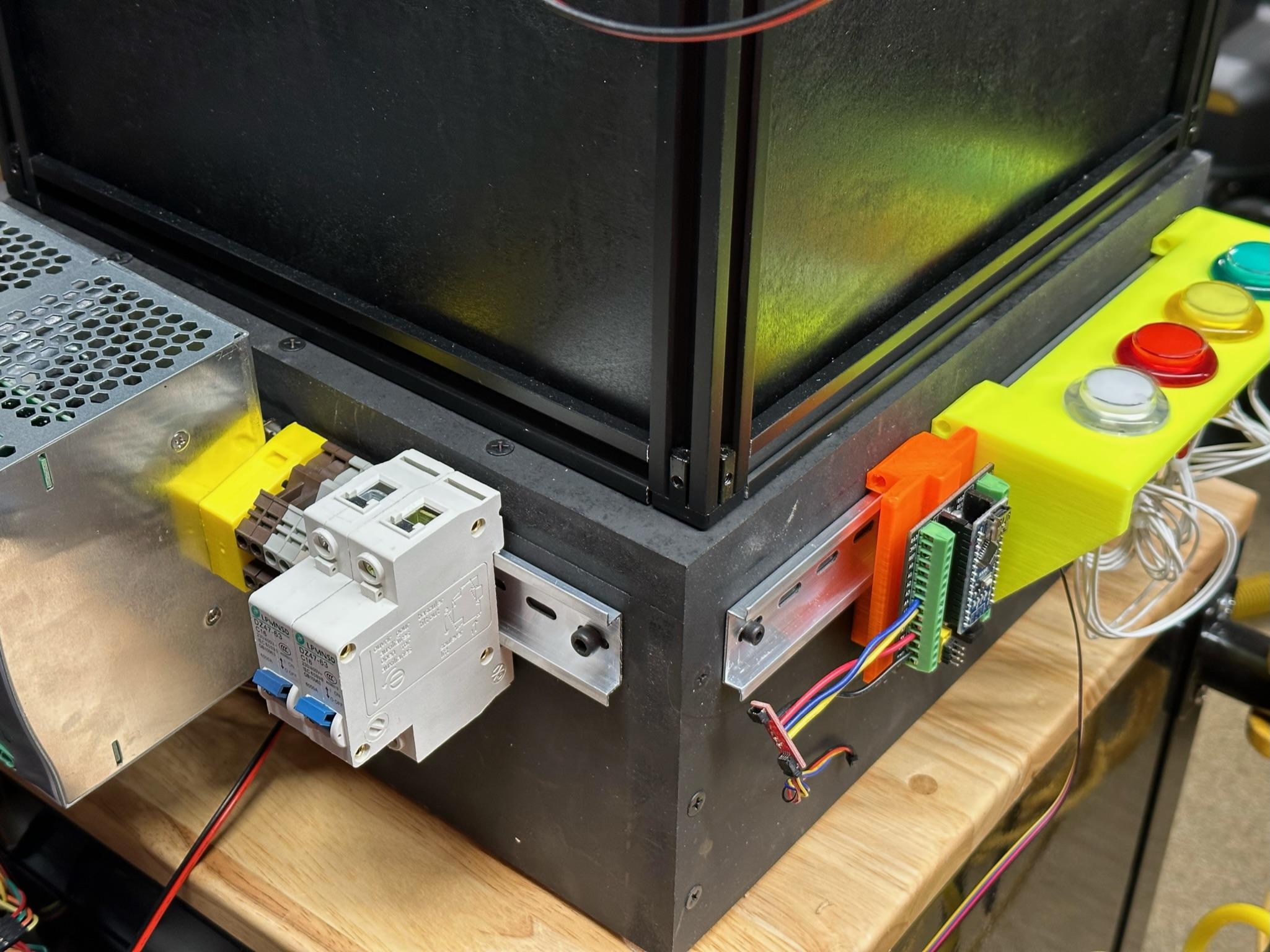
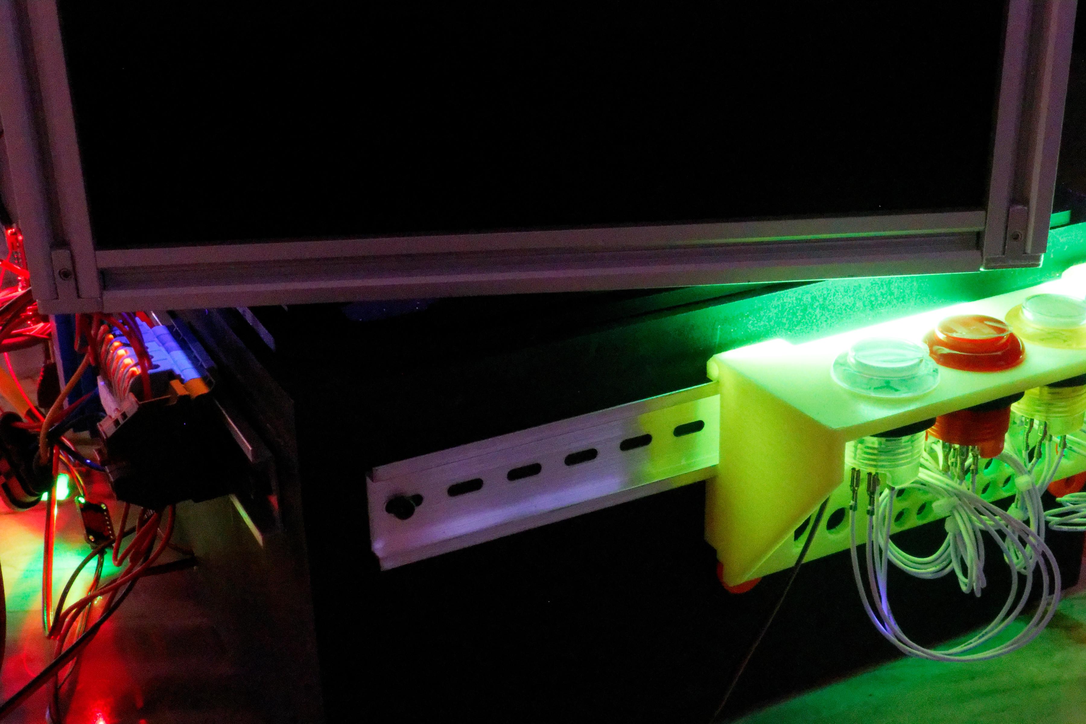
Modifications to the Base Part 2
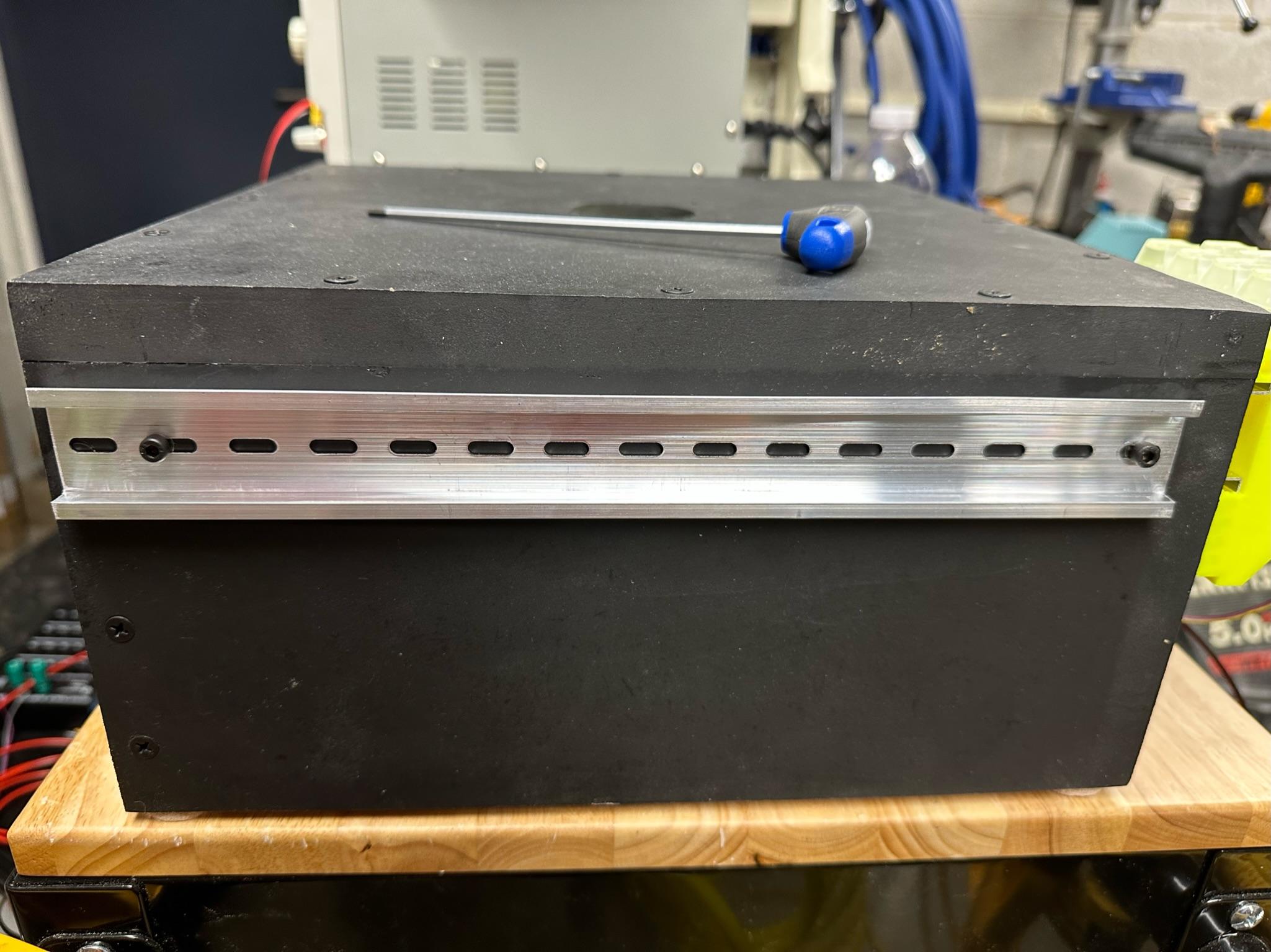

The second change we made was using the same wood inserts to add din rails to the outside of the base. This provides a convenient place to mount the controls for the lighting and stage control systems, as well as the power supplies and support equipment.
We used 10-inch strips of 7mm aluminum din rail mounted outside the base. The din rail was mounted ~35mm from the top of the base. We marked a spot 35mm from each side and drilled a pilot hole. We then screwed a mount into each hole. We use a black sharpy to color the brass to hide the insert. We then screwed the din rail in using 5mm bolts.
You can remove the din rails if you want to do a different photo project or use the base for a display case.
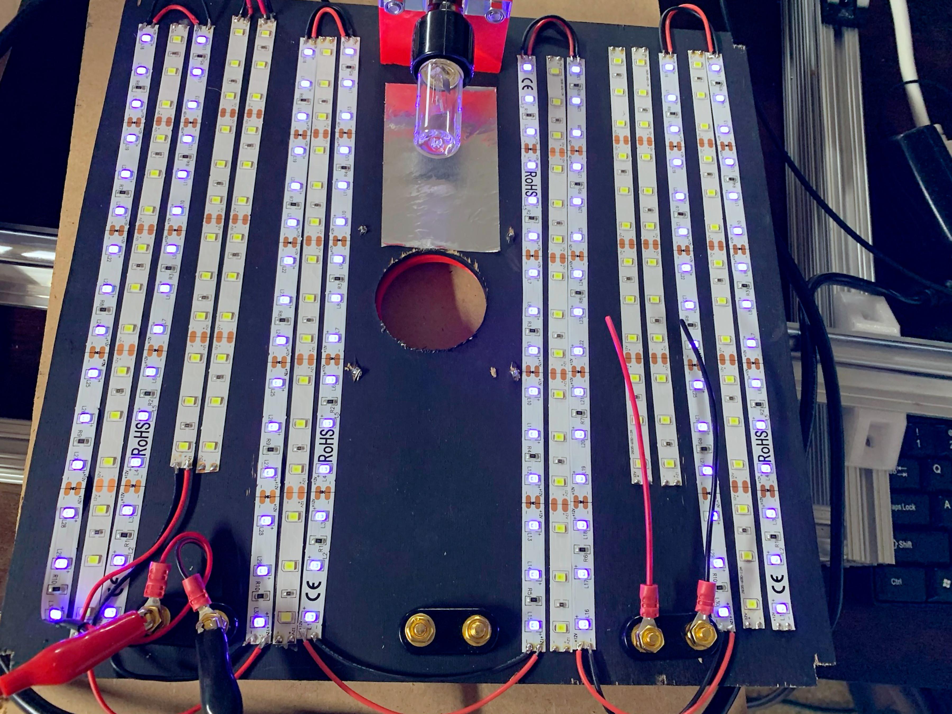
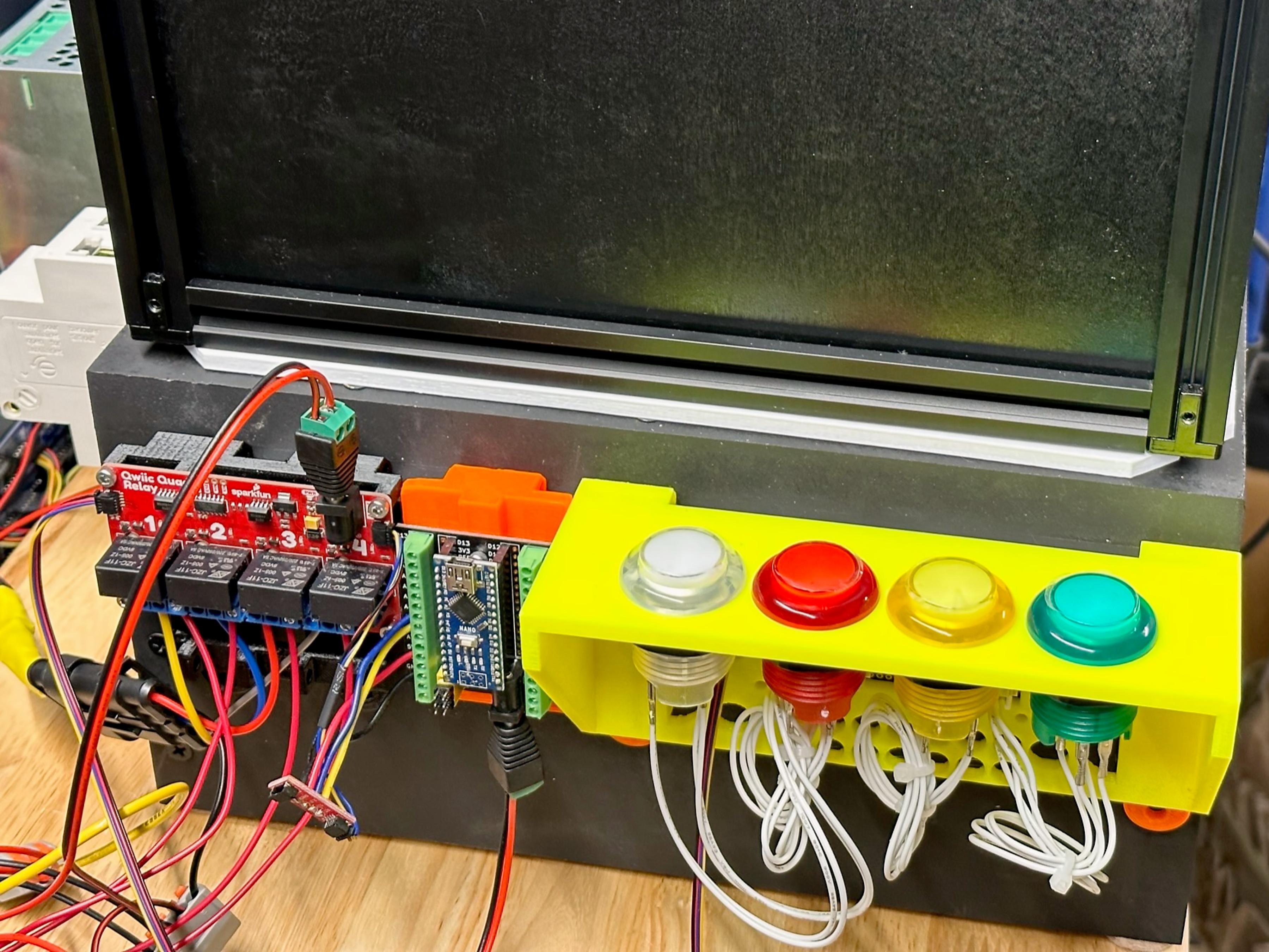
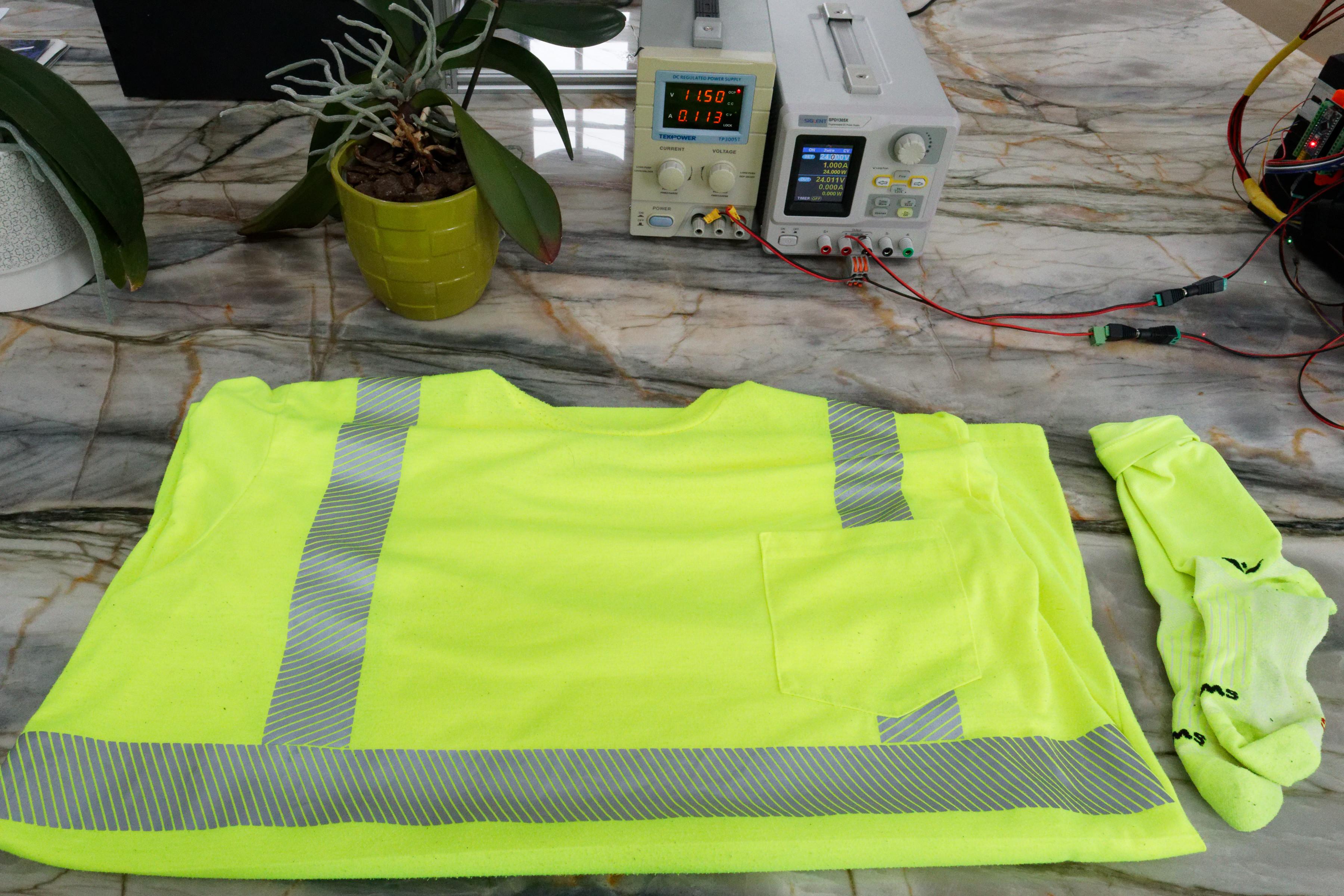
The Lighting Control System
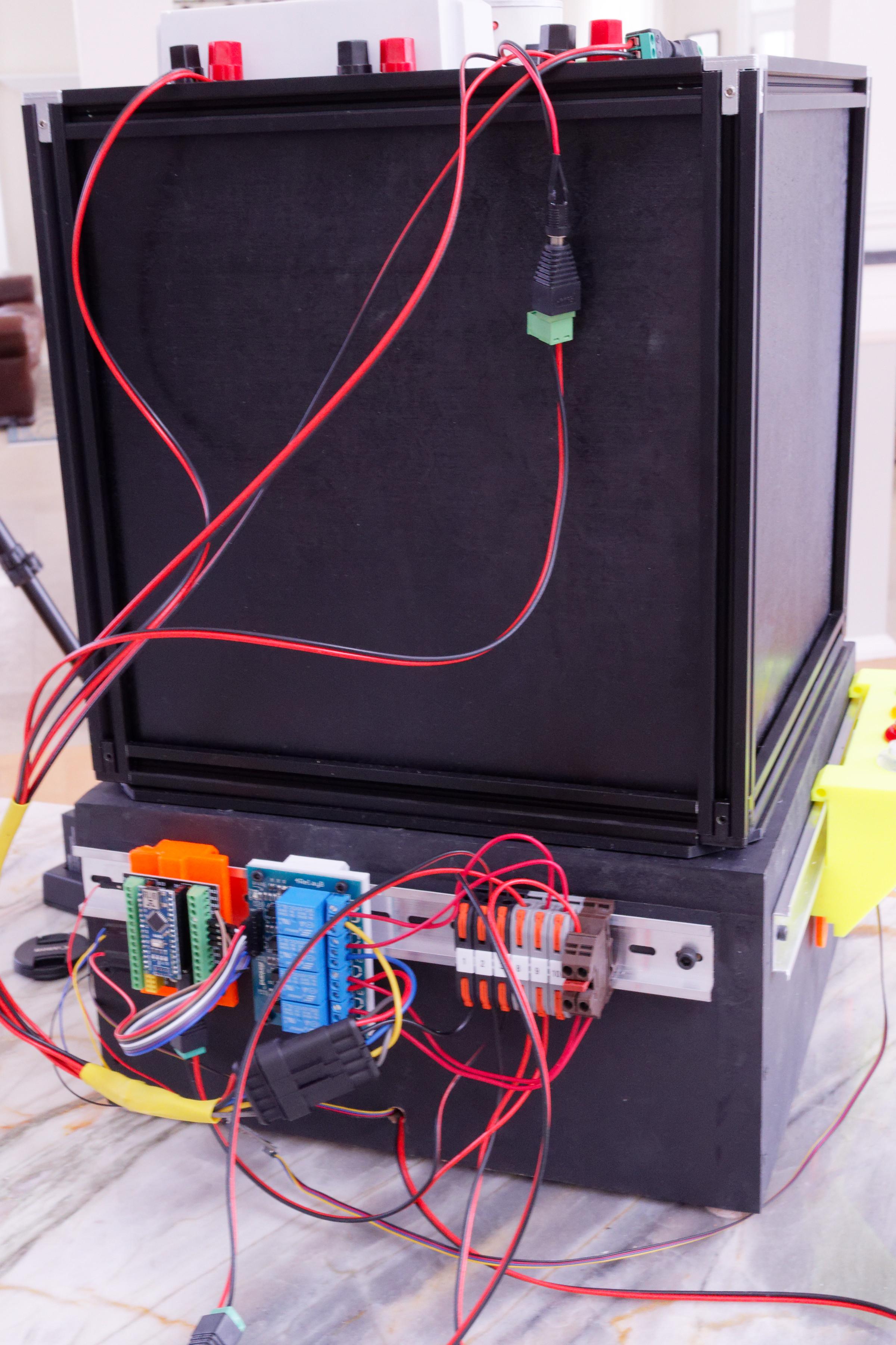
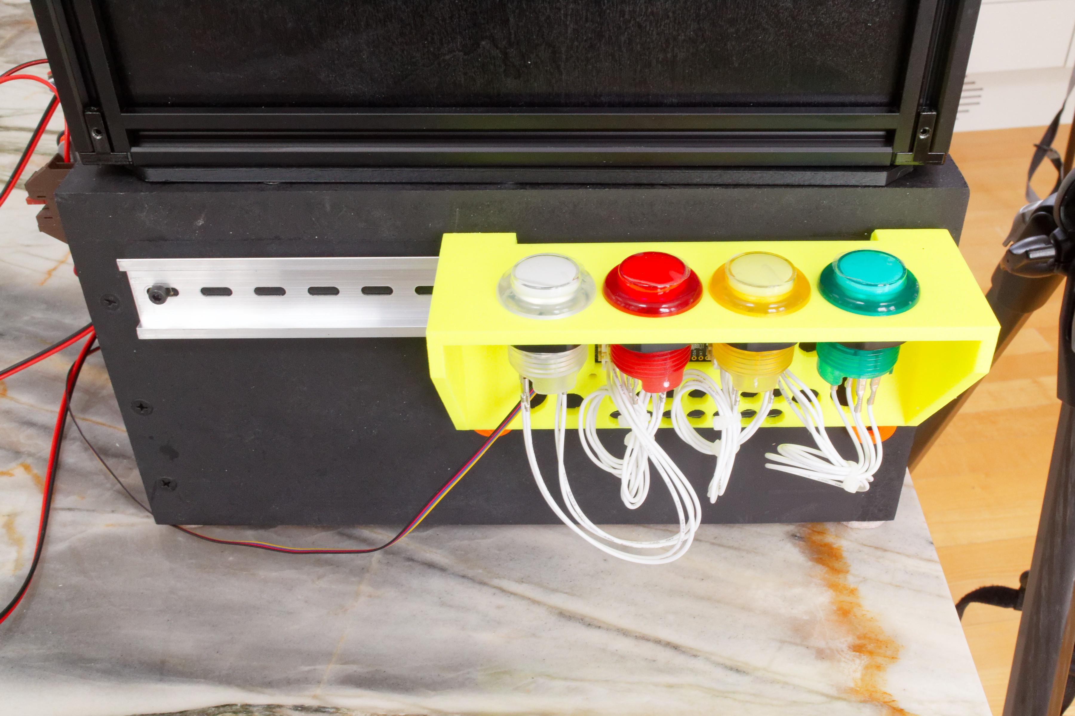
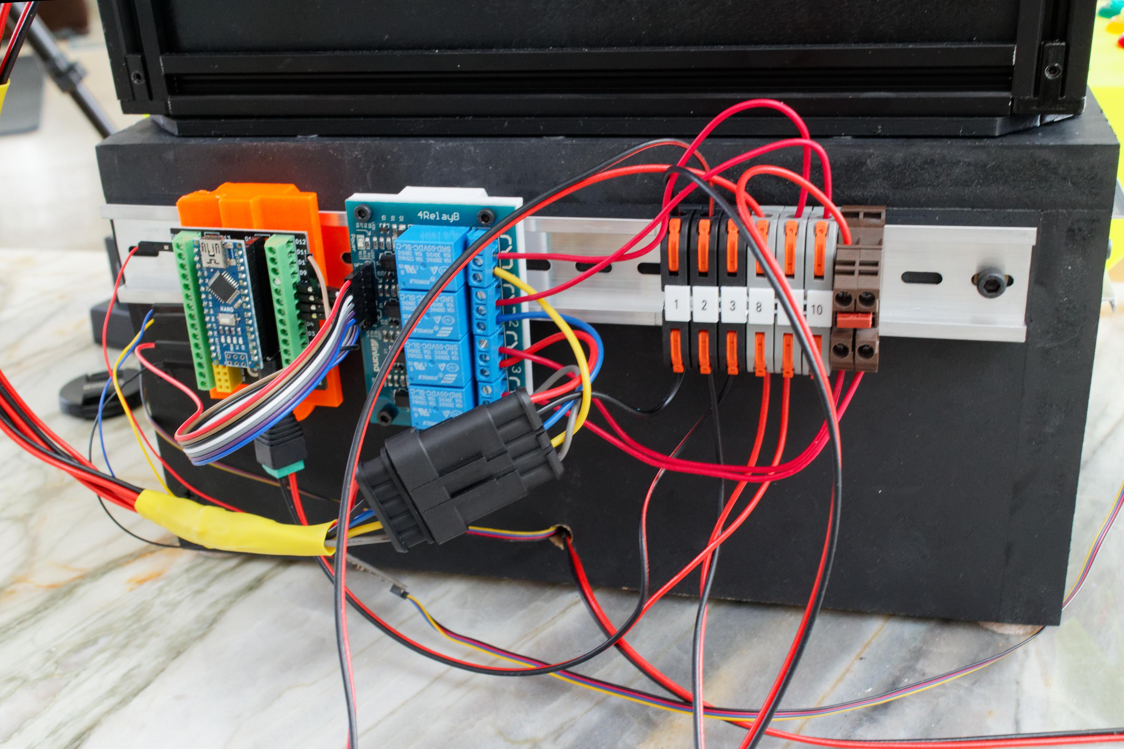
We constructed a simple light control system to switch between different lighting sources. It was constructed using an Adafruit arcade button controller, an Arduino NANO, and a simple four-position relay board. The relay module switched two 12V lines and two 24V lines. The 12v lines controlled daylight led strips and 400nm uv strips. The 24V relays controlled power to the 264nm bulb and the power supply of the 222nm excimer lamp.
Do you think this needs to be its own instructable?
Arcade button mount: Printables Thingiverse
Nano mount: Printables Thingiverse
Relay mount: Printables Thingiverse
Downloads
The Stage Control System
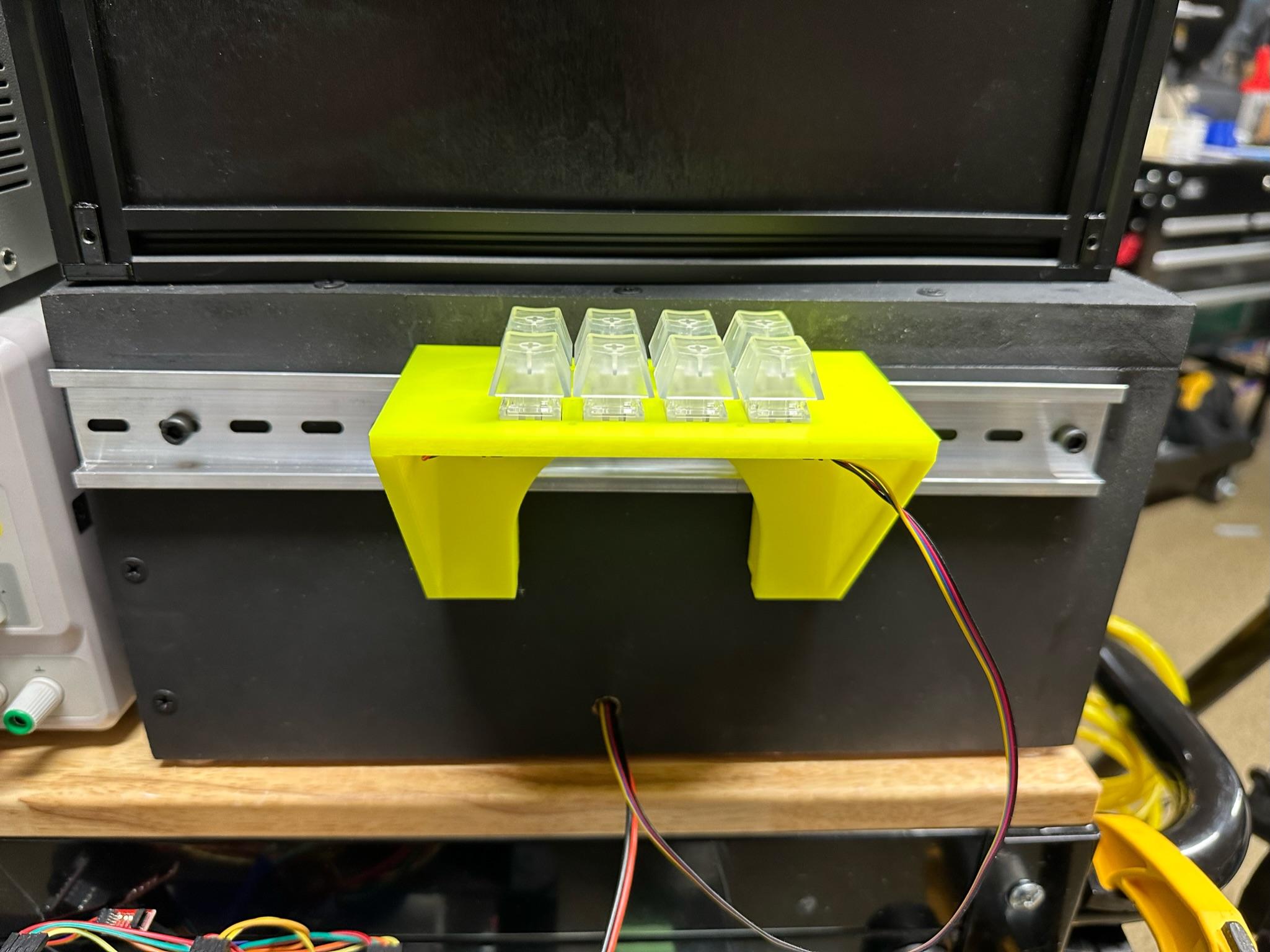
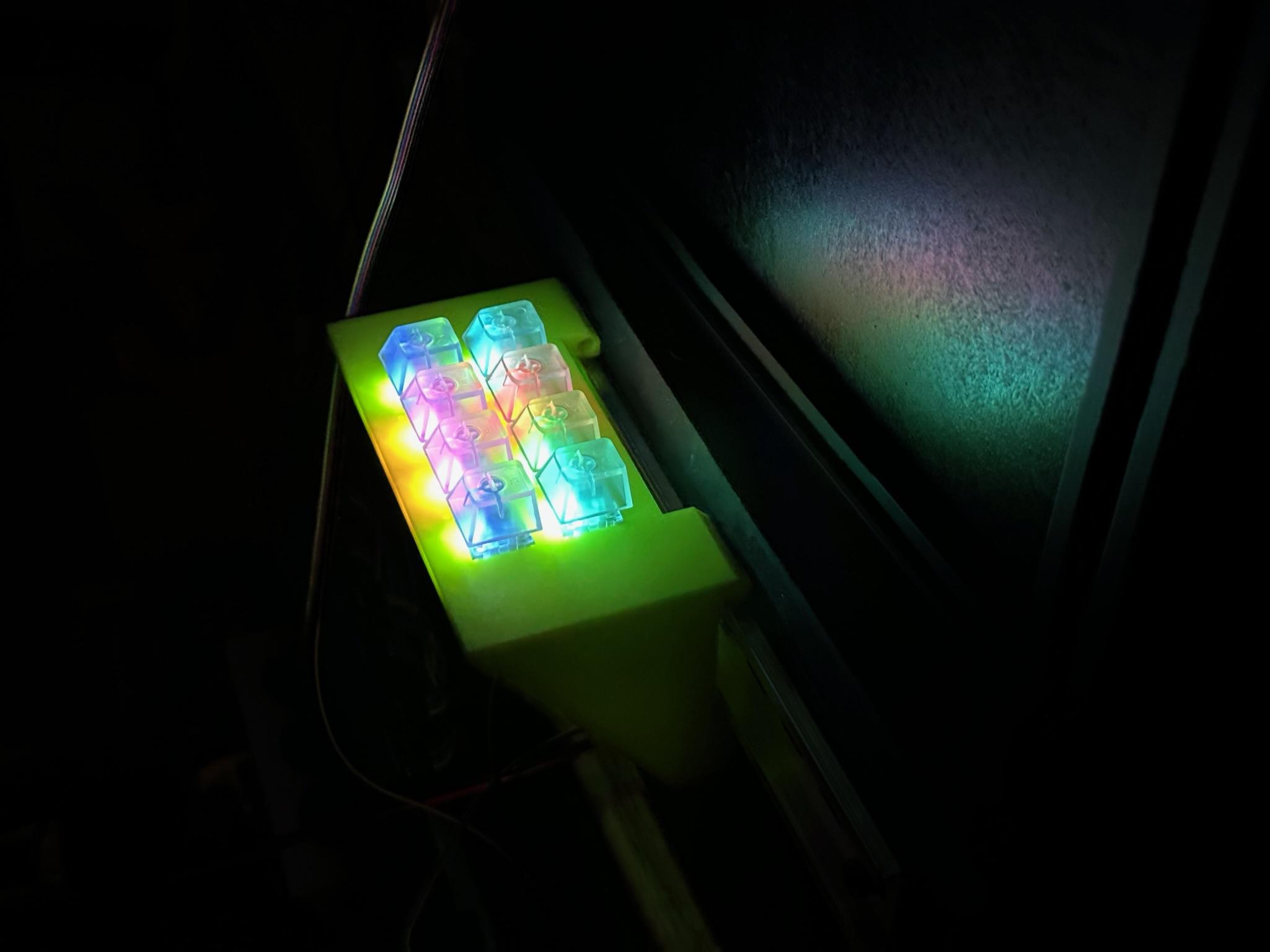
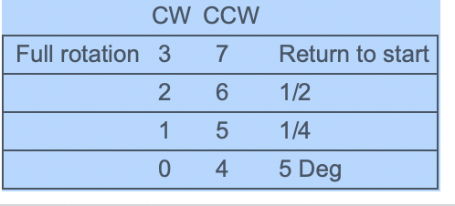
The Stage control system is detailed in our instructable "A Simple Rotating Stage for Photography or Display." The only modifications we made were to rotate the controller buttons. The updated code is attached.
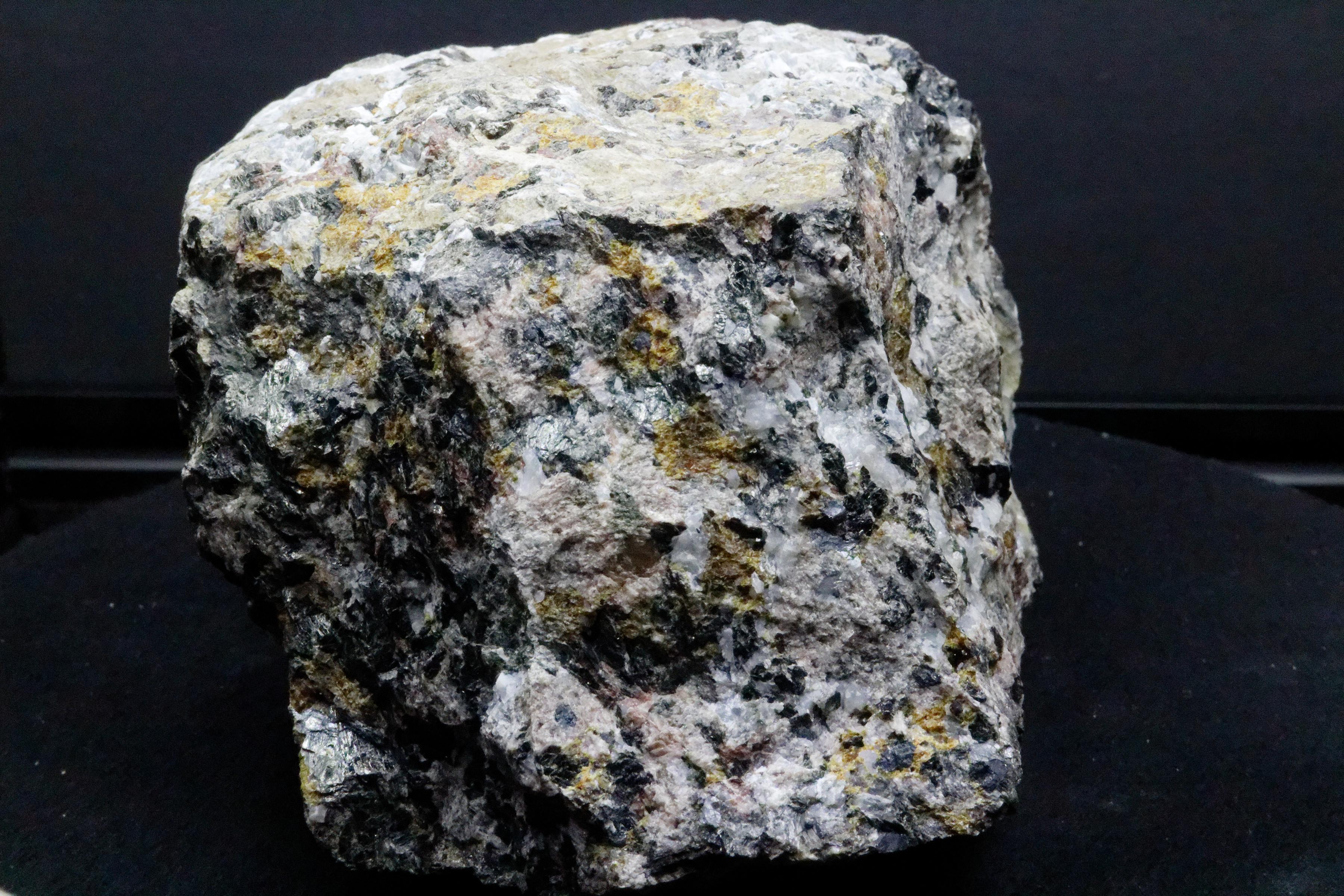
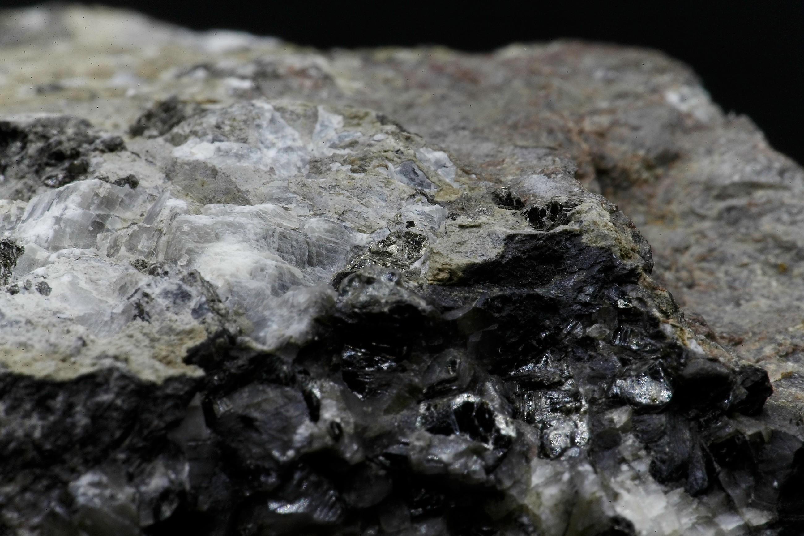
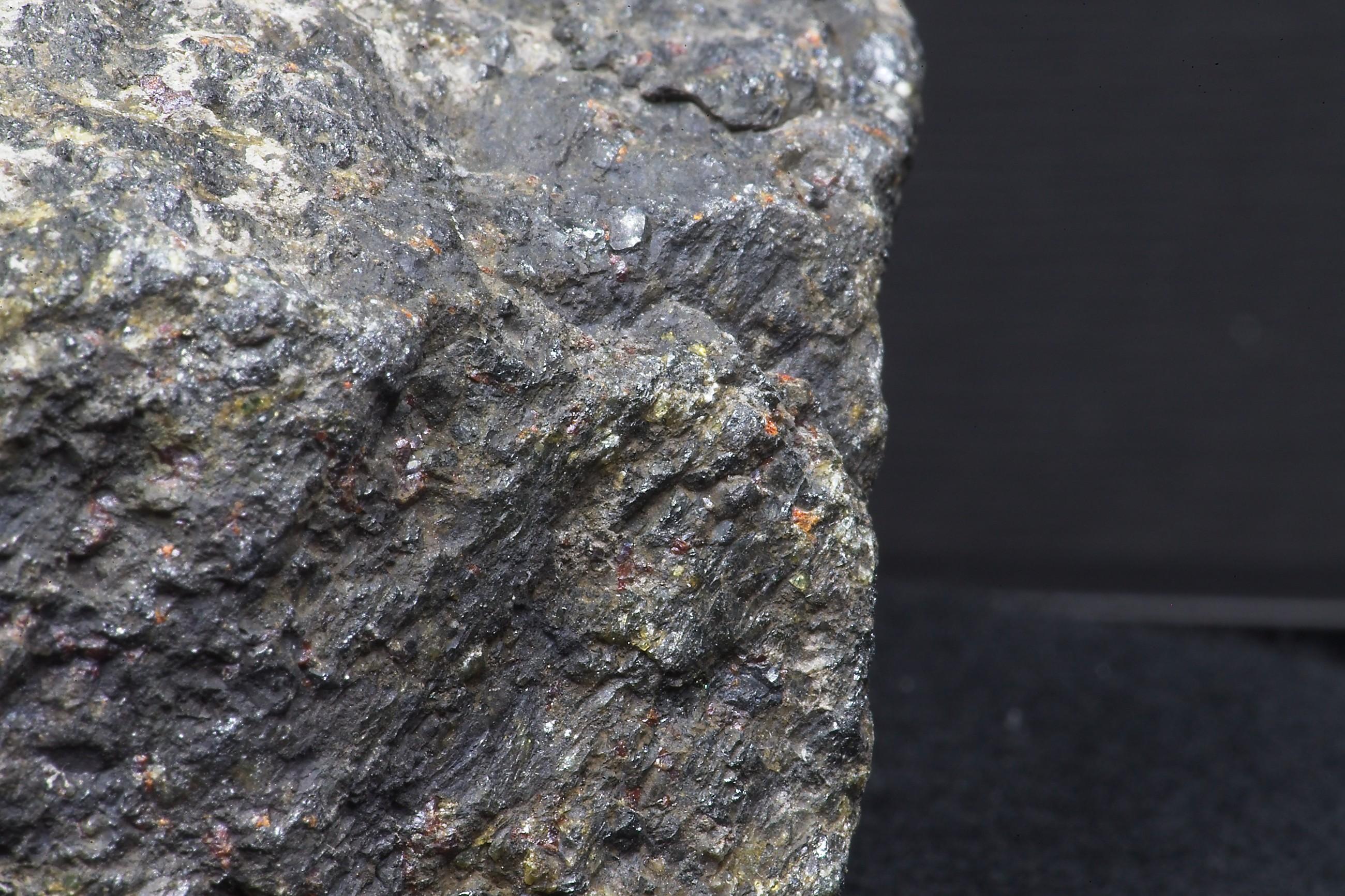
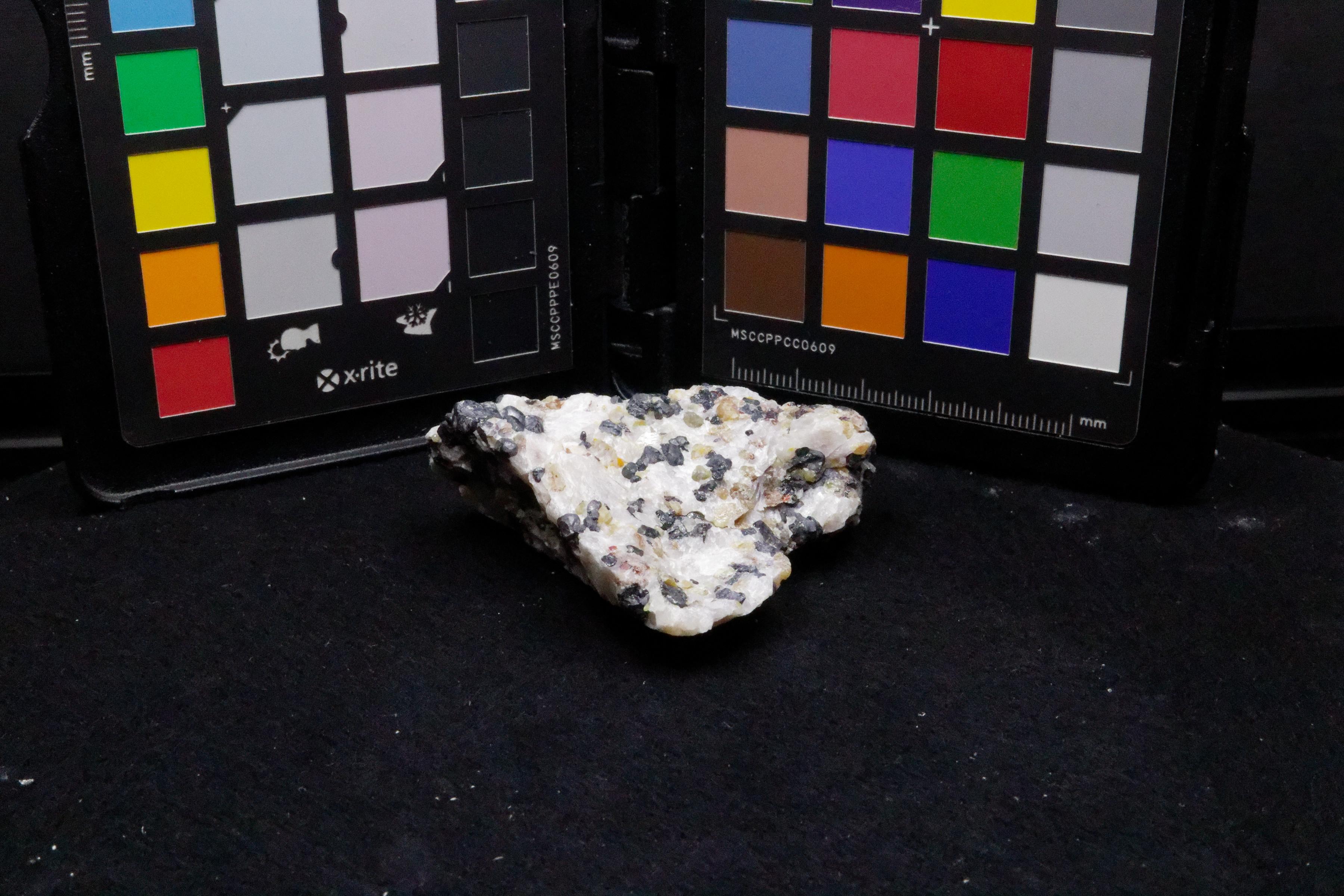
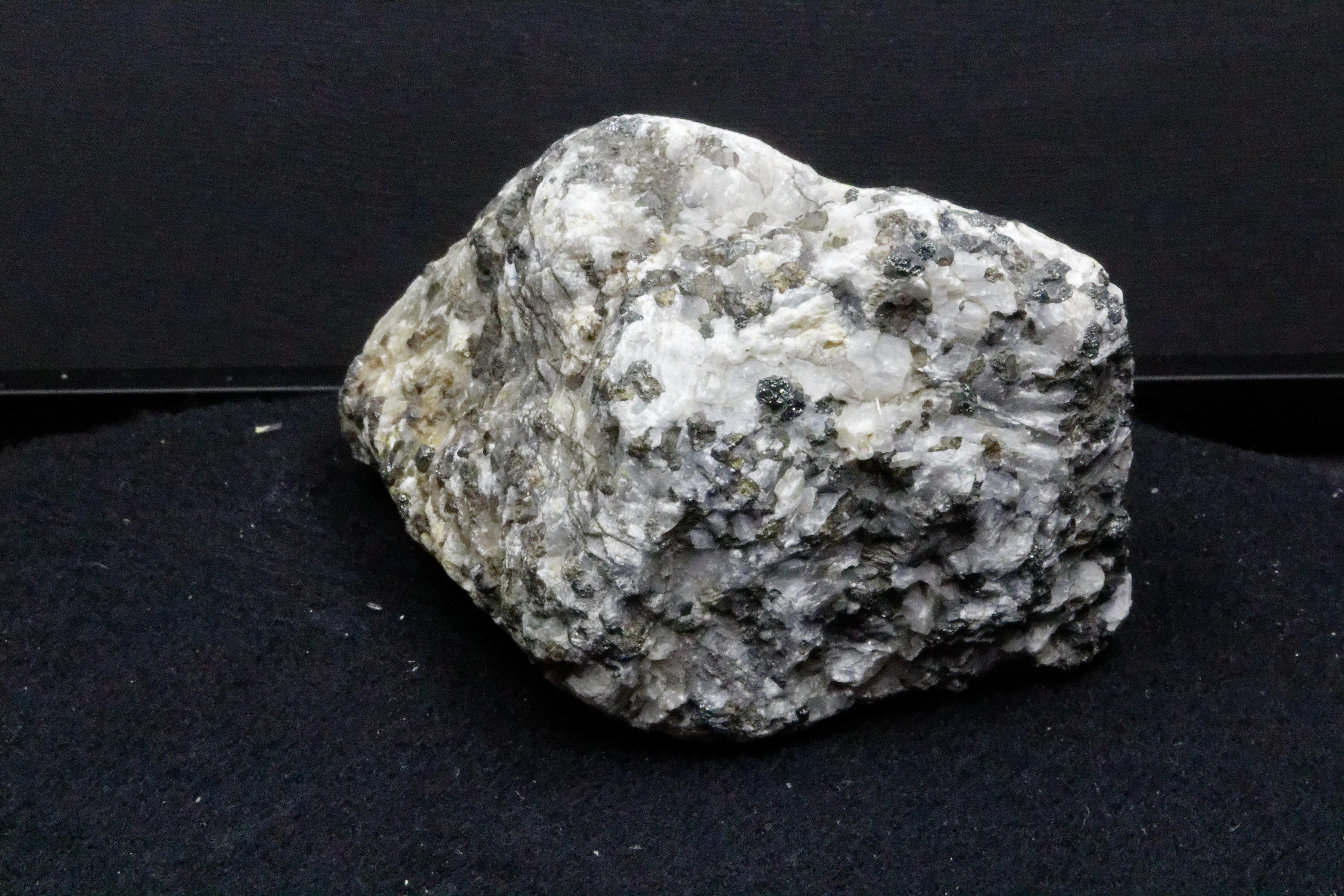
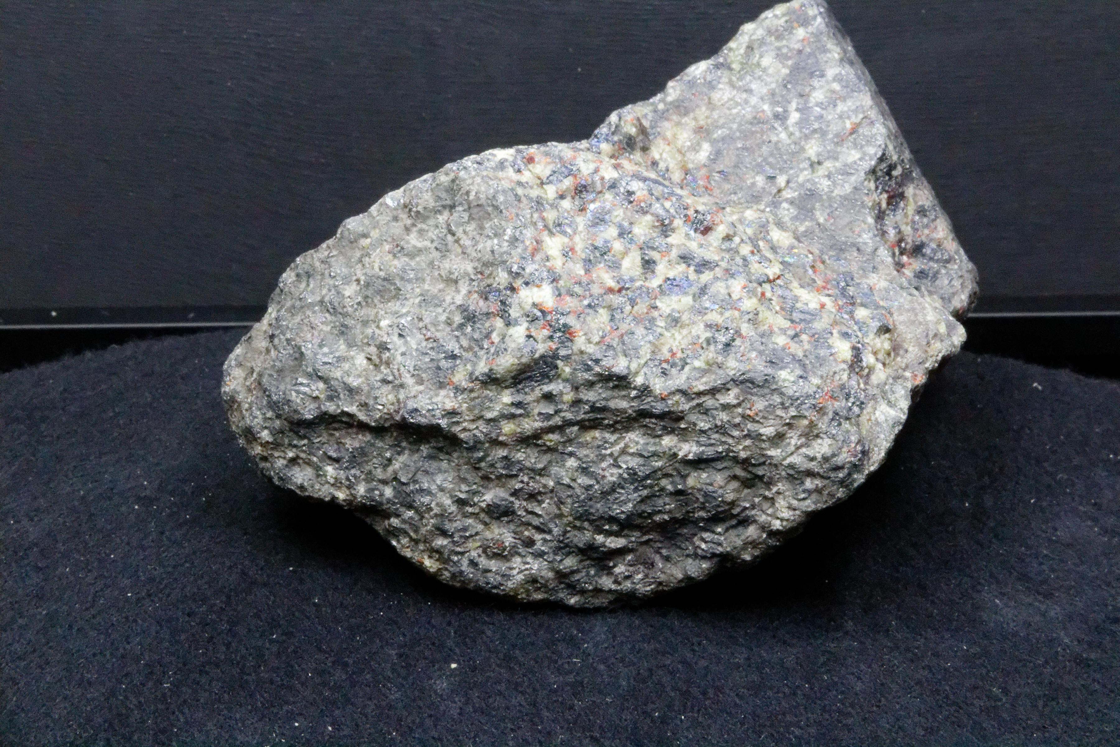
Visible Light

We do not have a spectrum for the "white" light.
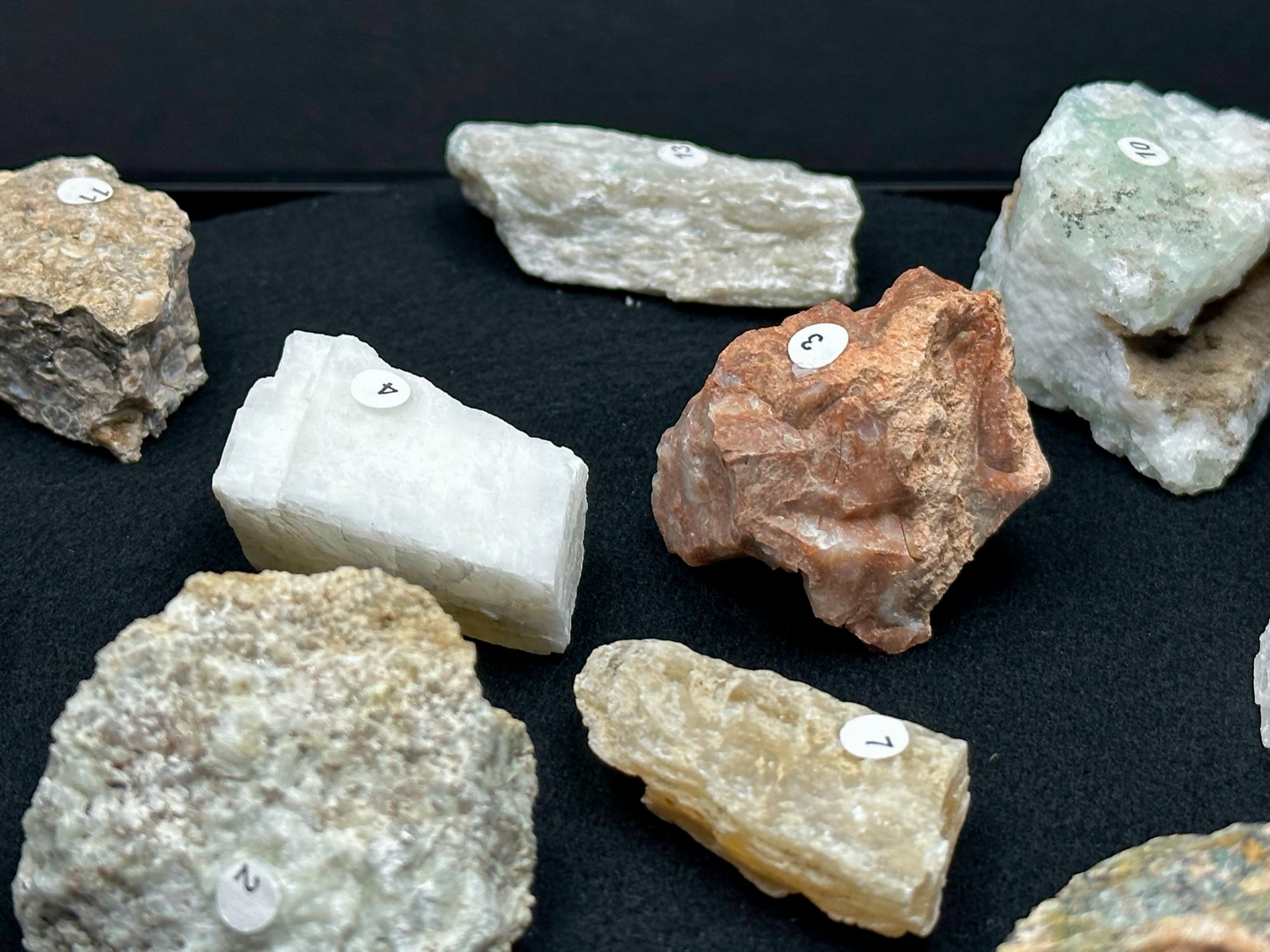
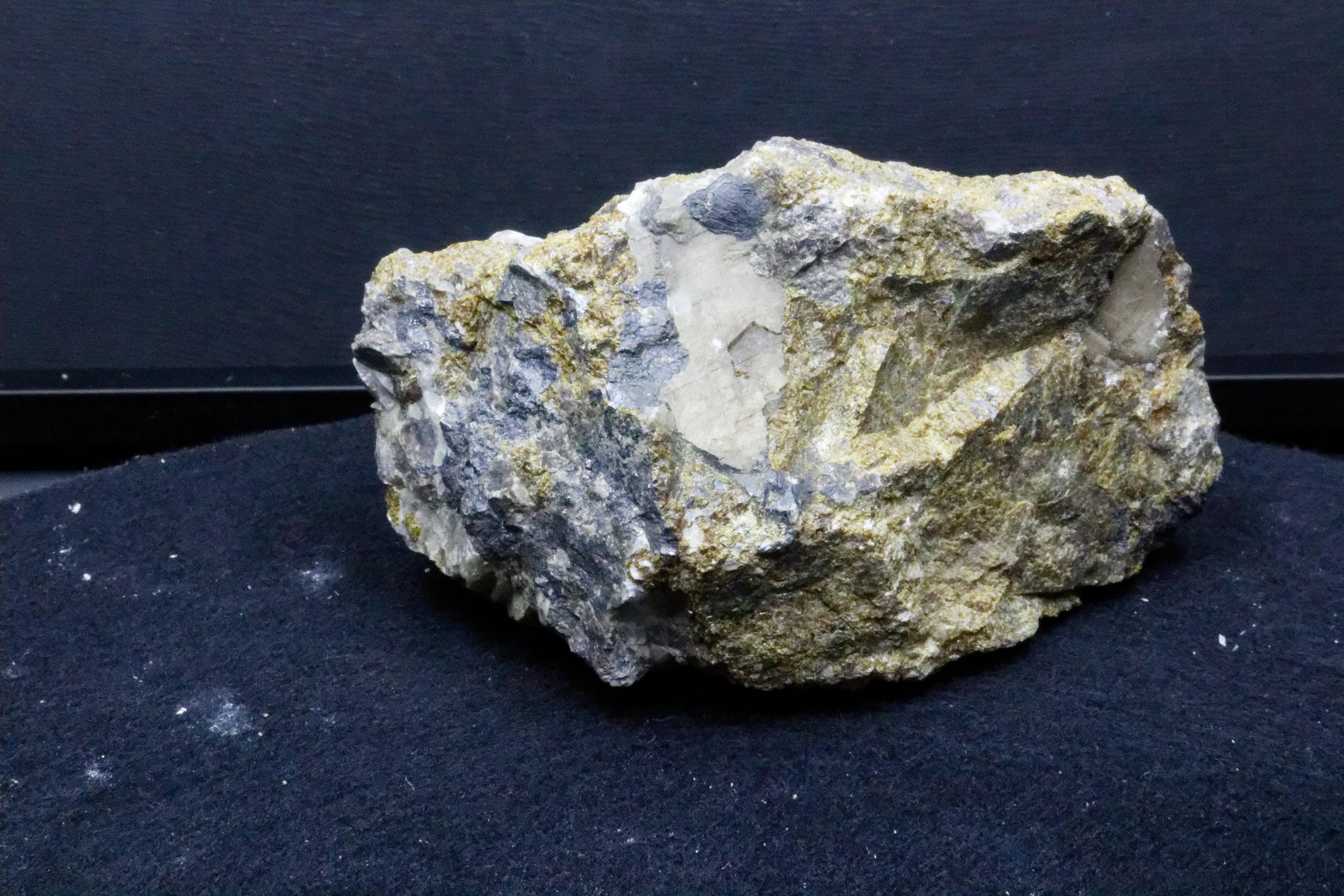
The rock looks like a rock, which is great for setting your focus and finding interesting topological features.
We used LED strips from Amazon. The LEDs were 6000k to approximate daylight. They were leftovers from another project and used 12V. This made them compatible with the power supply we used for powering the turntable, the 400nm LEDs, and Arduino Nanos. We would only use half the number of led strips if we were doing the project again.
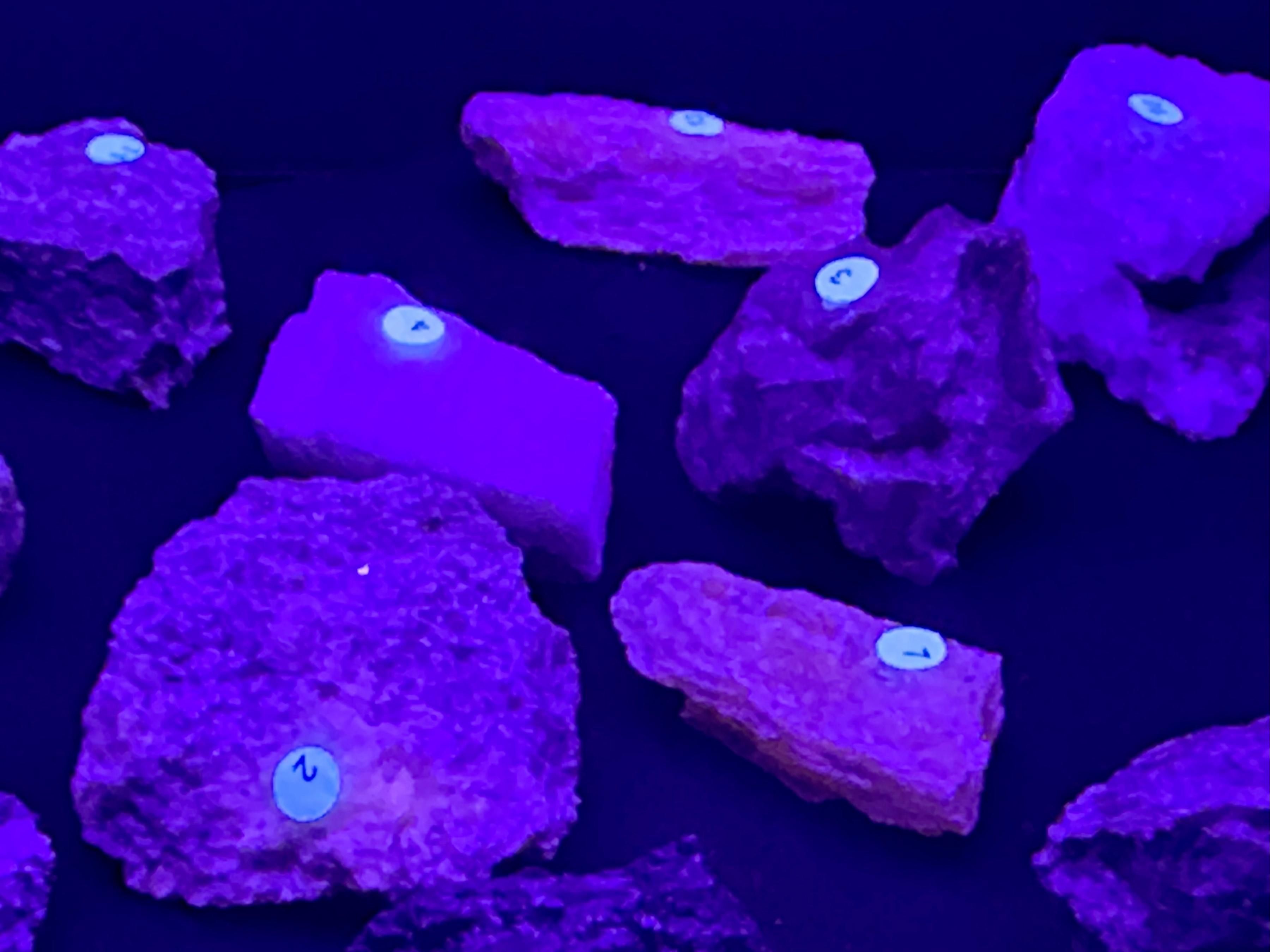
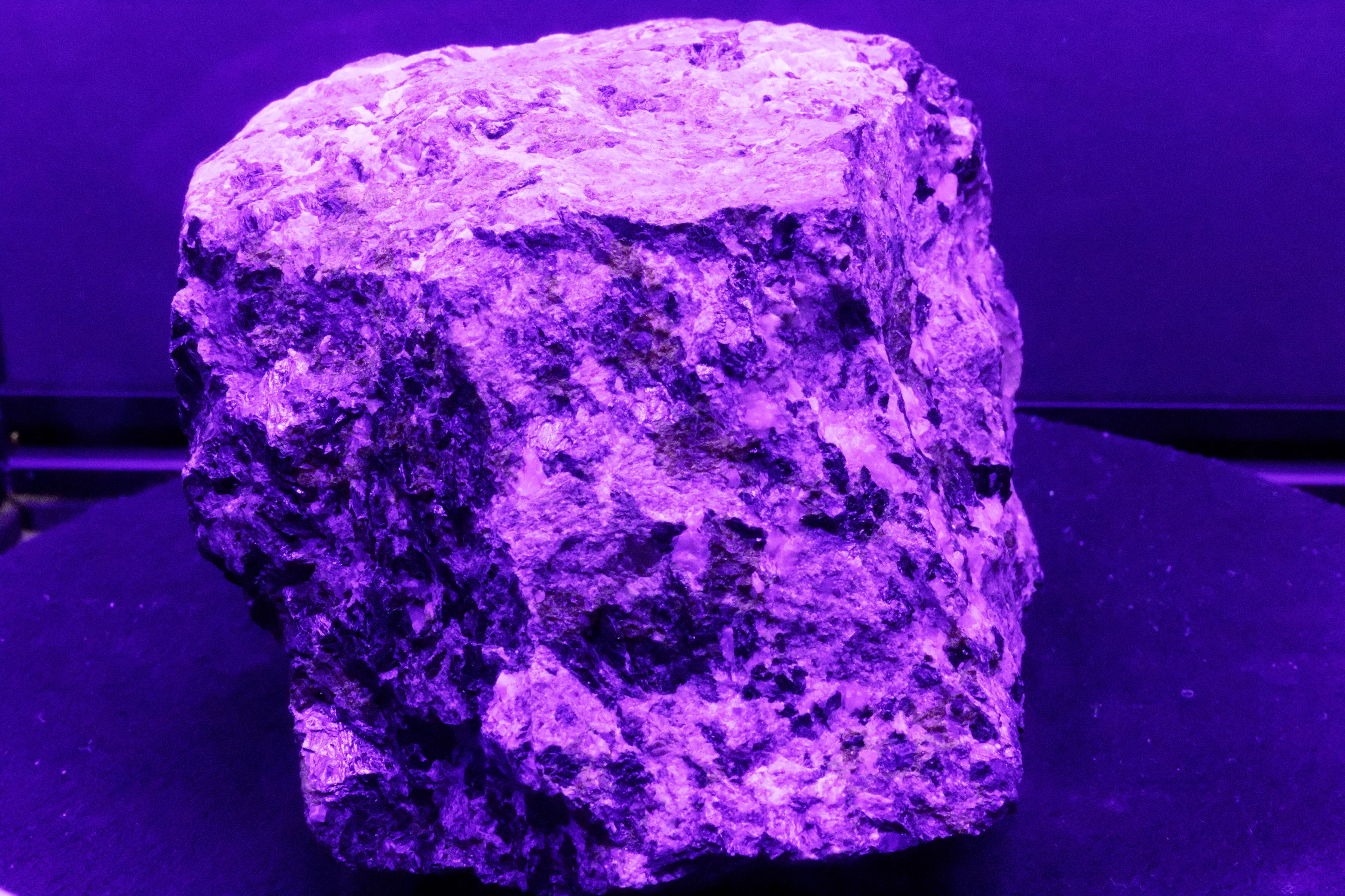
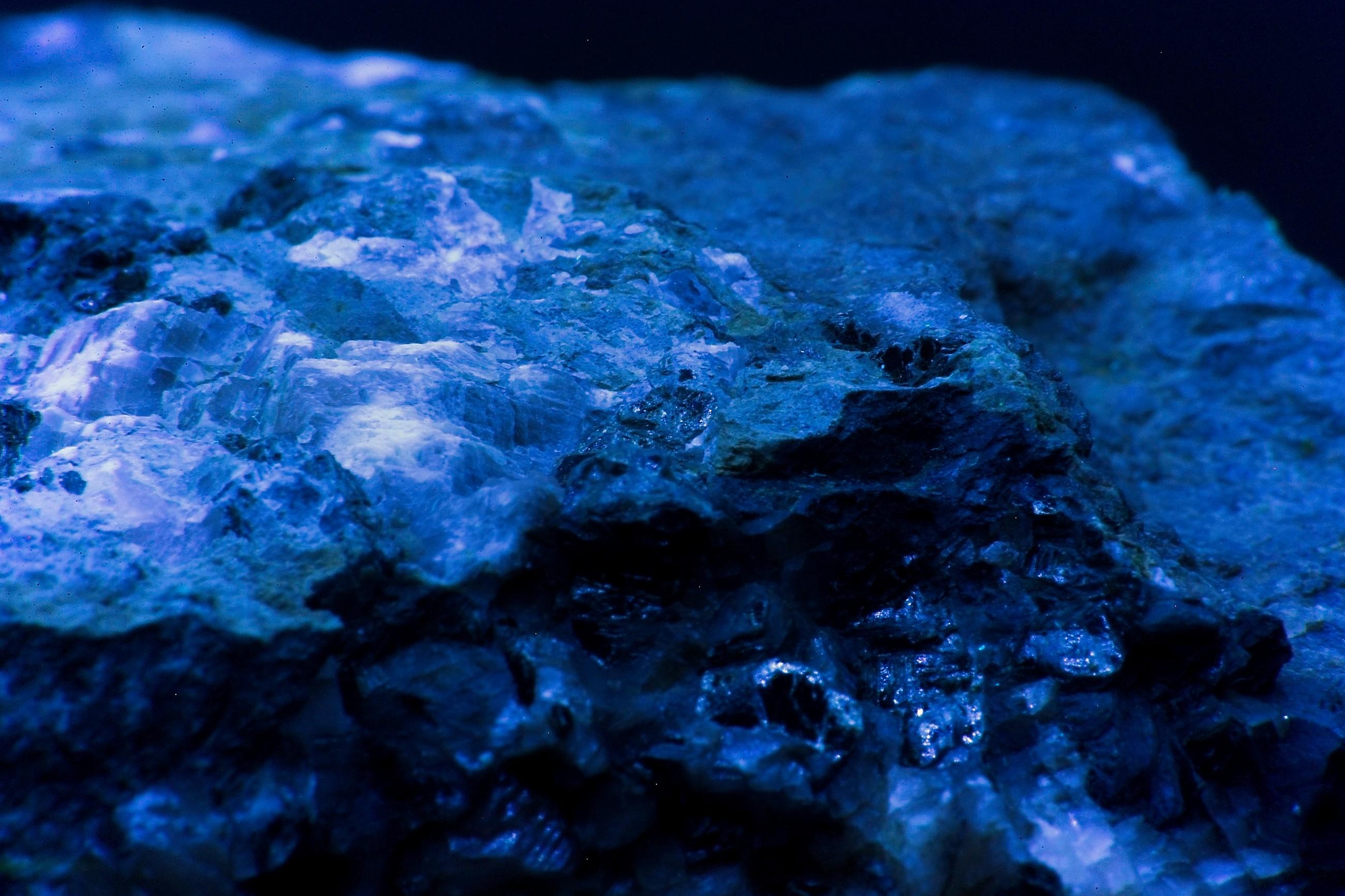
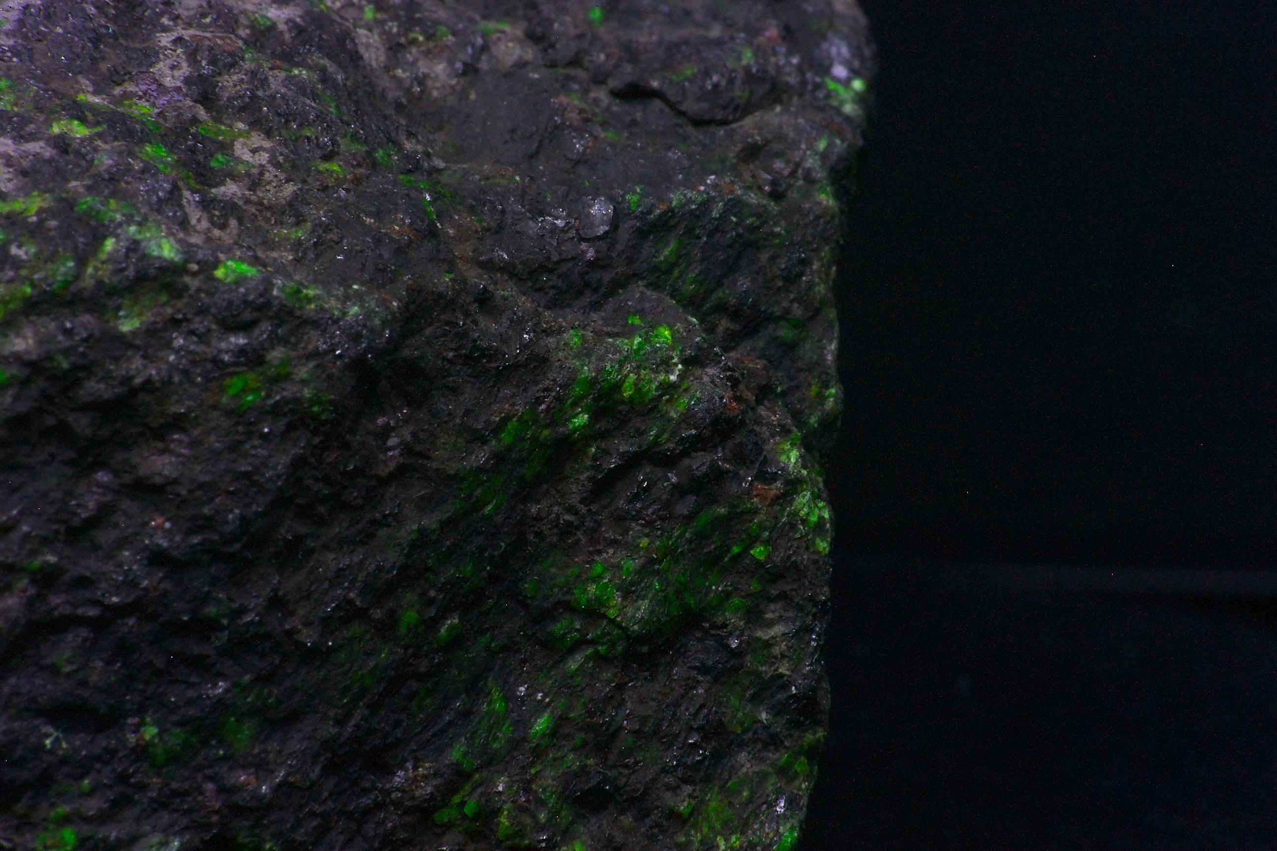
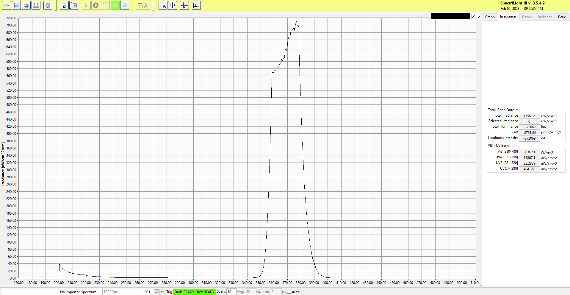
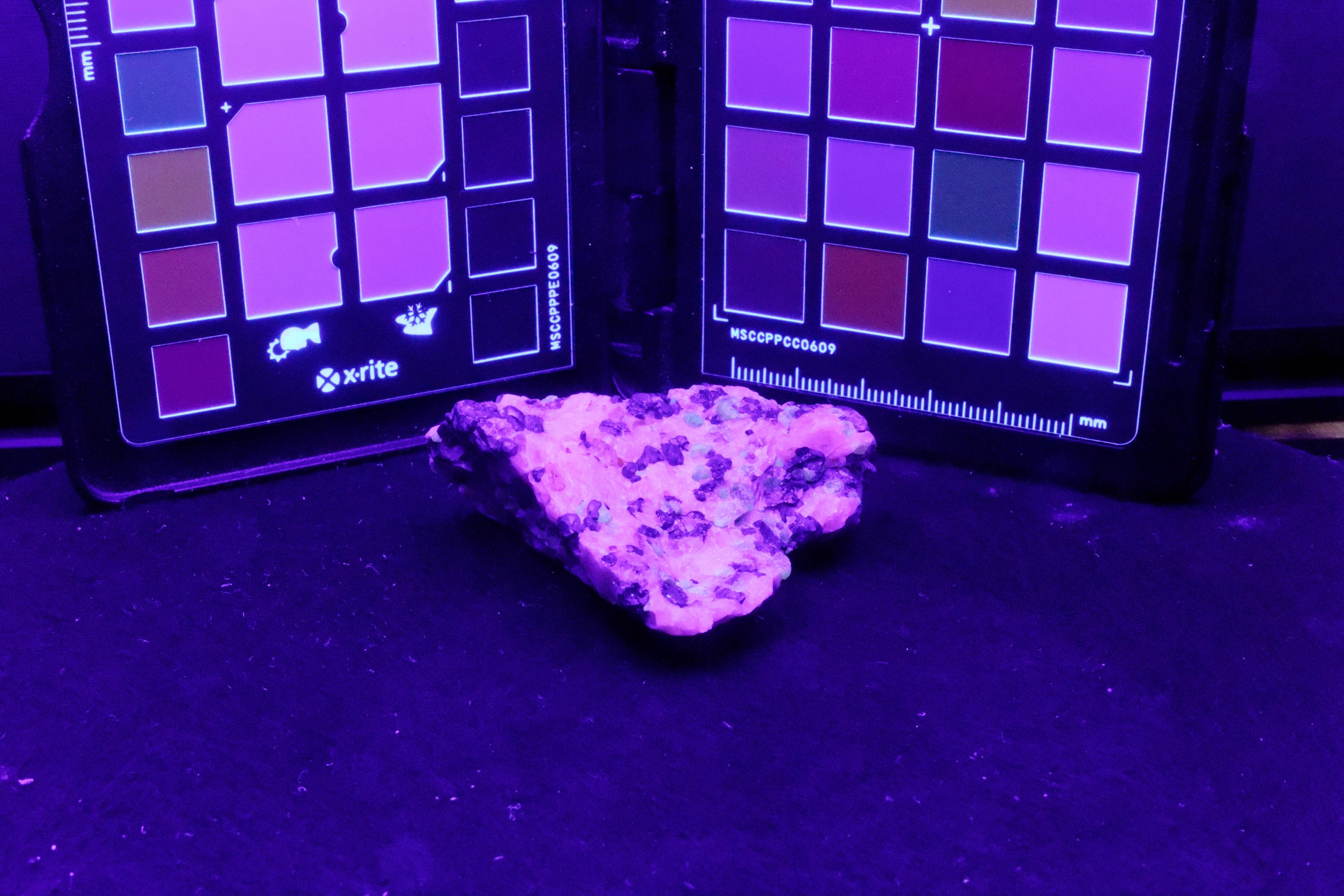
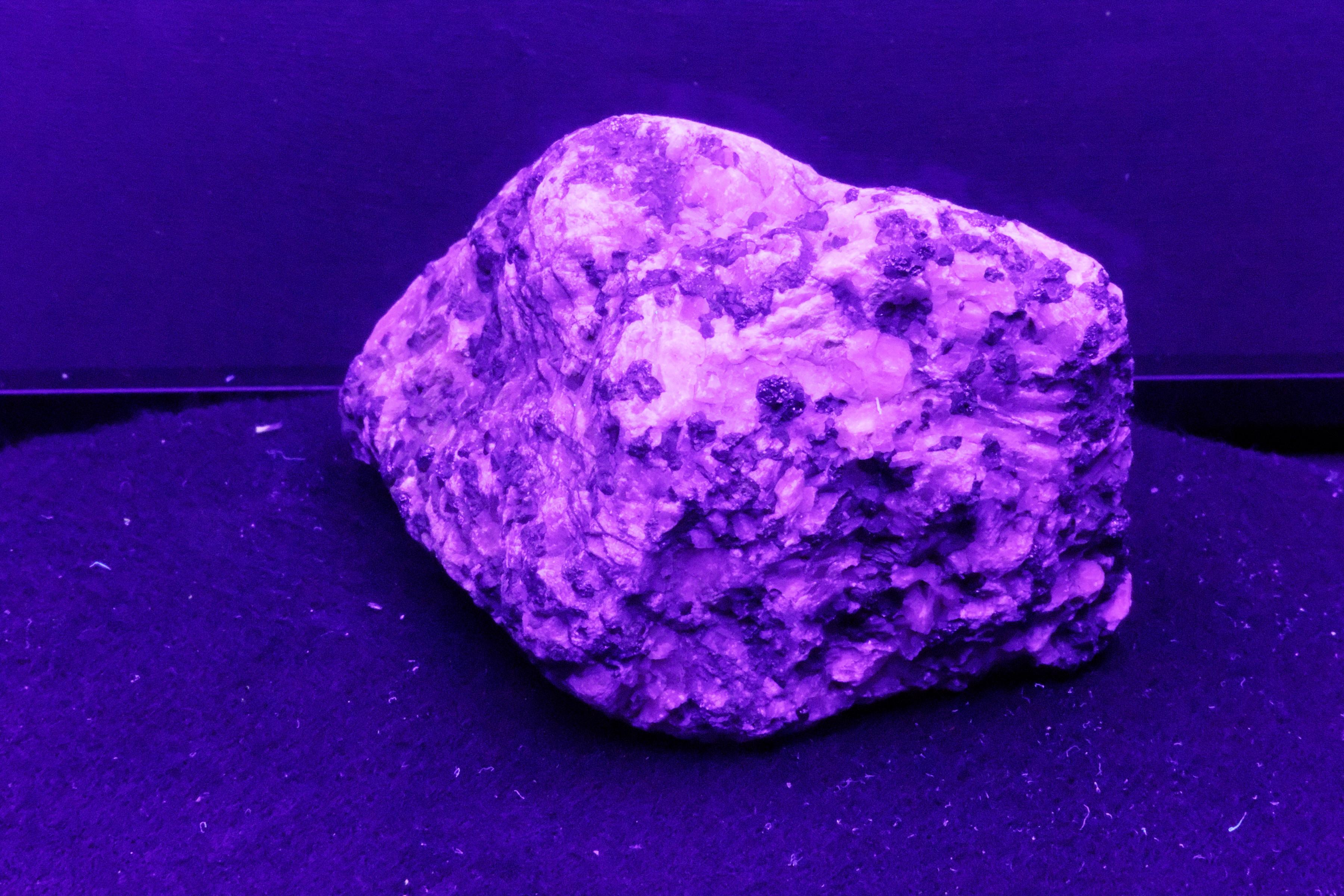
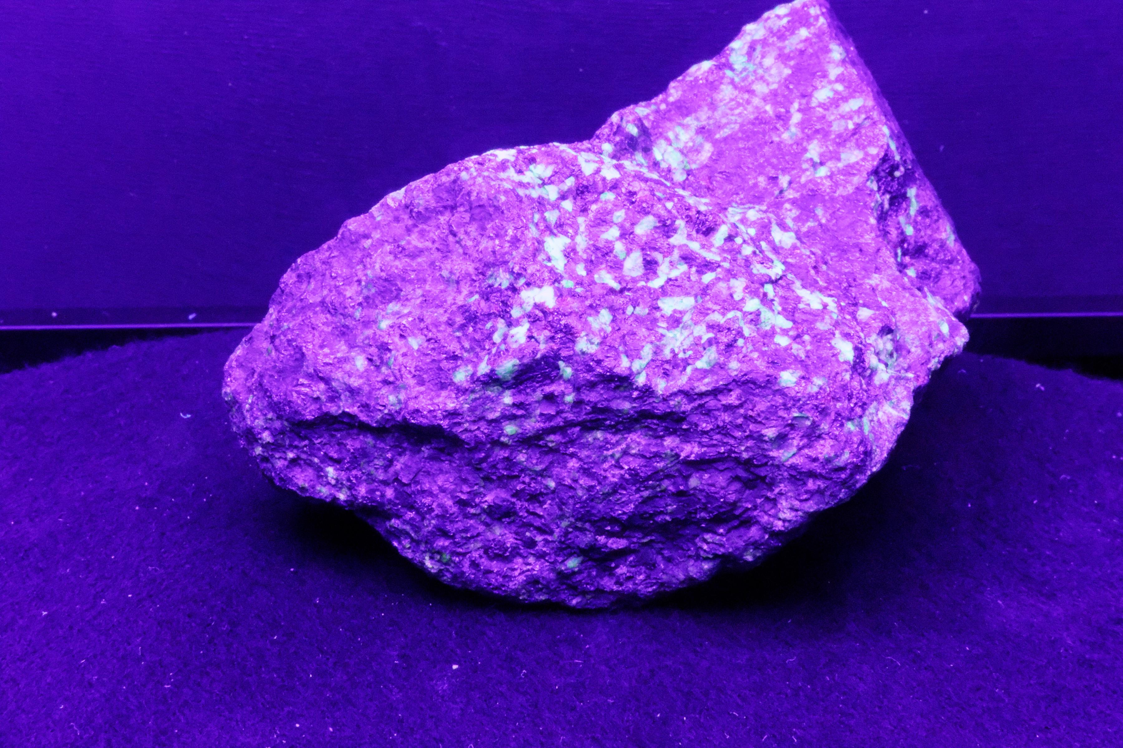
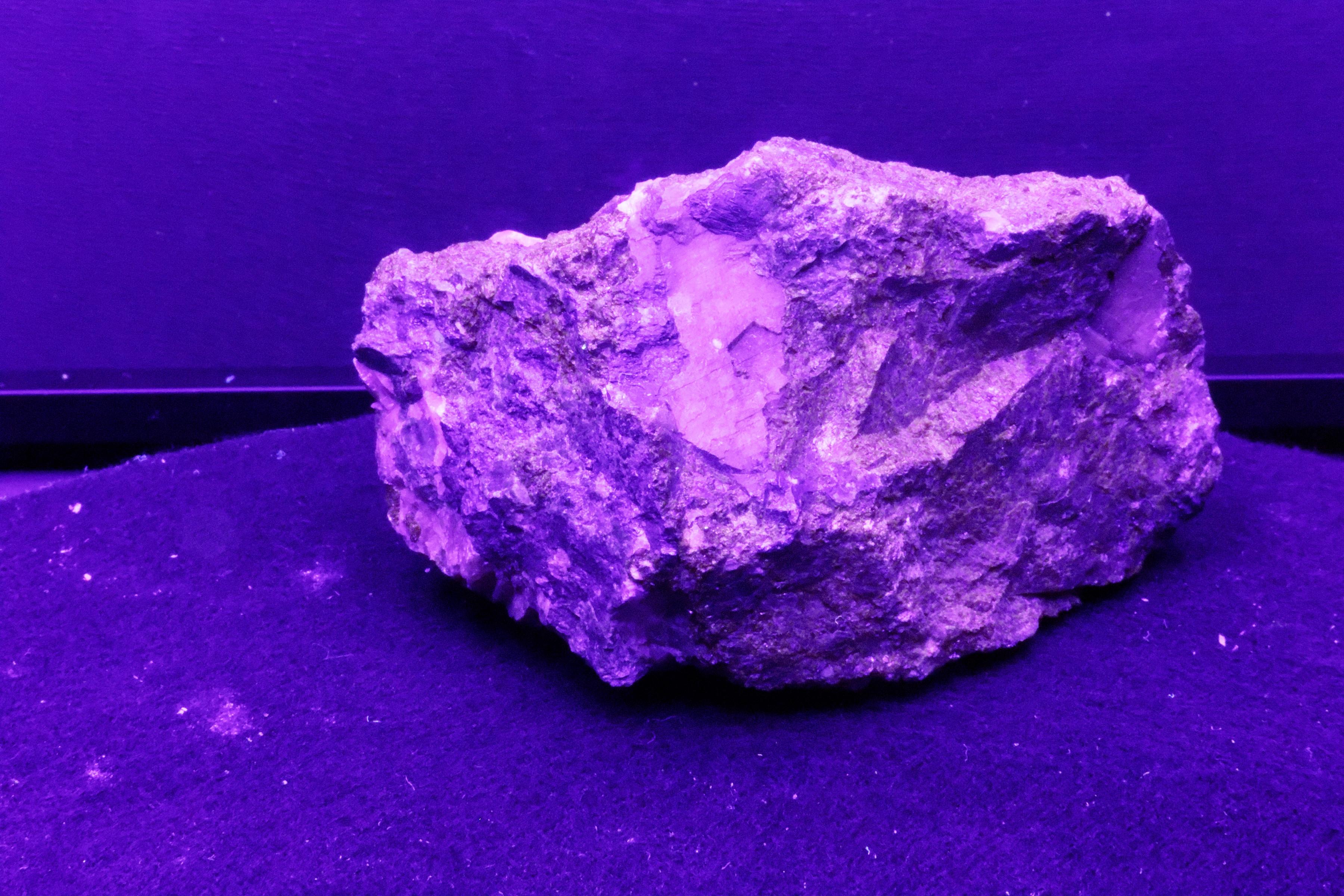
400nm
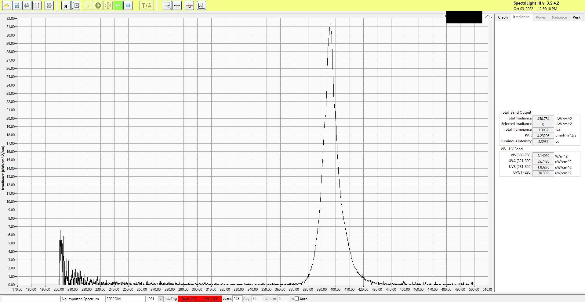
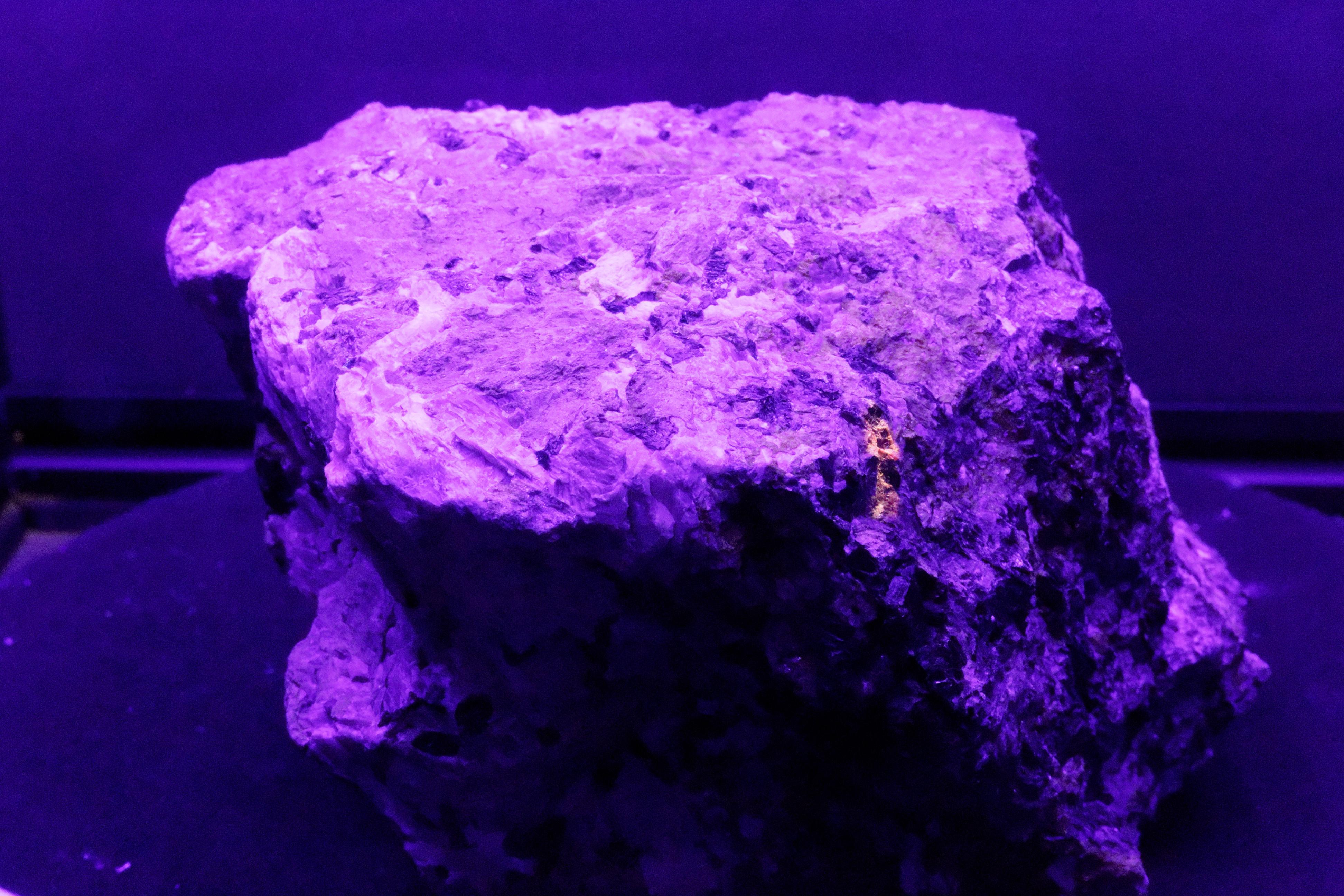
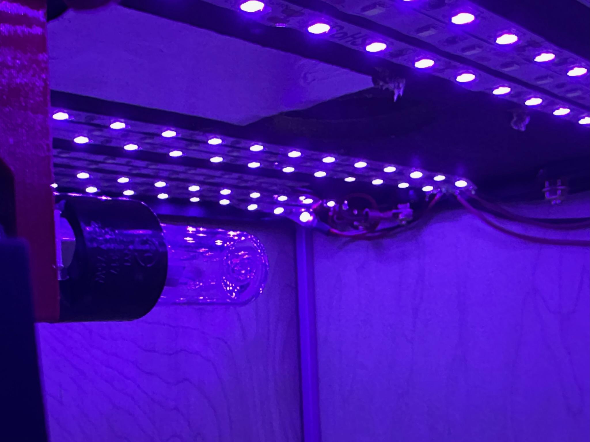
If you look at the spectrum of this light, you can see how wide the frequency spread is. A lot of the energy is in the visible part of the spectrum. This is why the rock has a purple cast. We would only use half the number of led strips if we were doing the project again.
We used UV-led strips from Amazon.
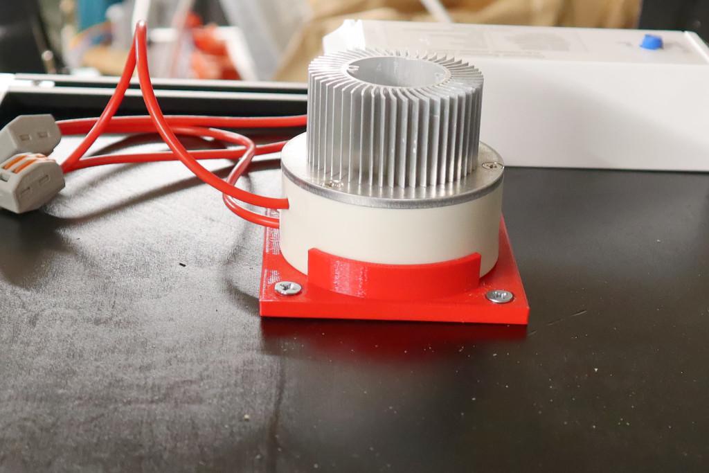
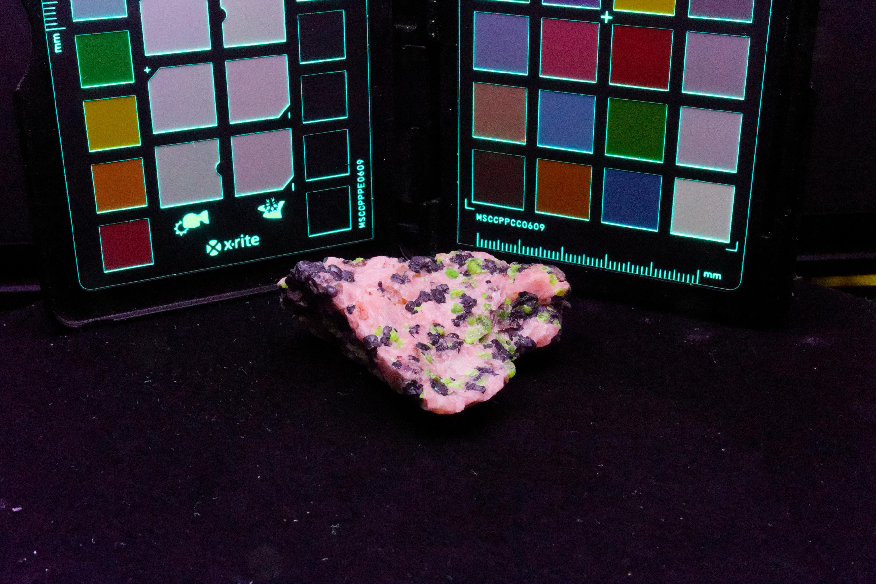
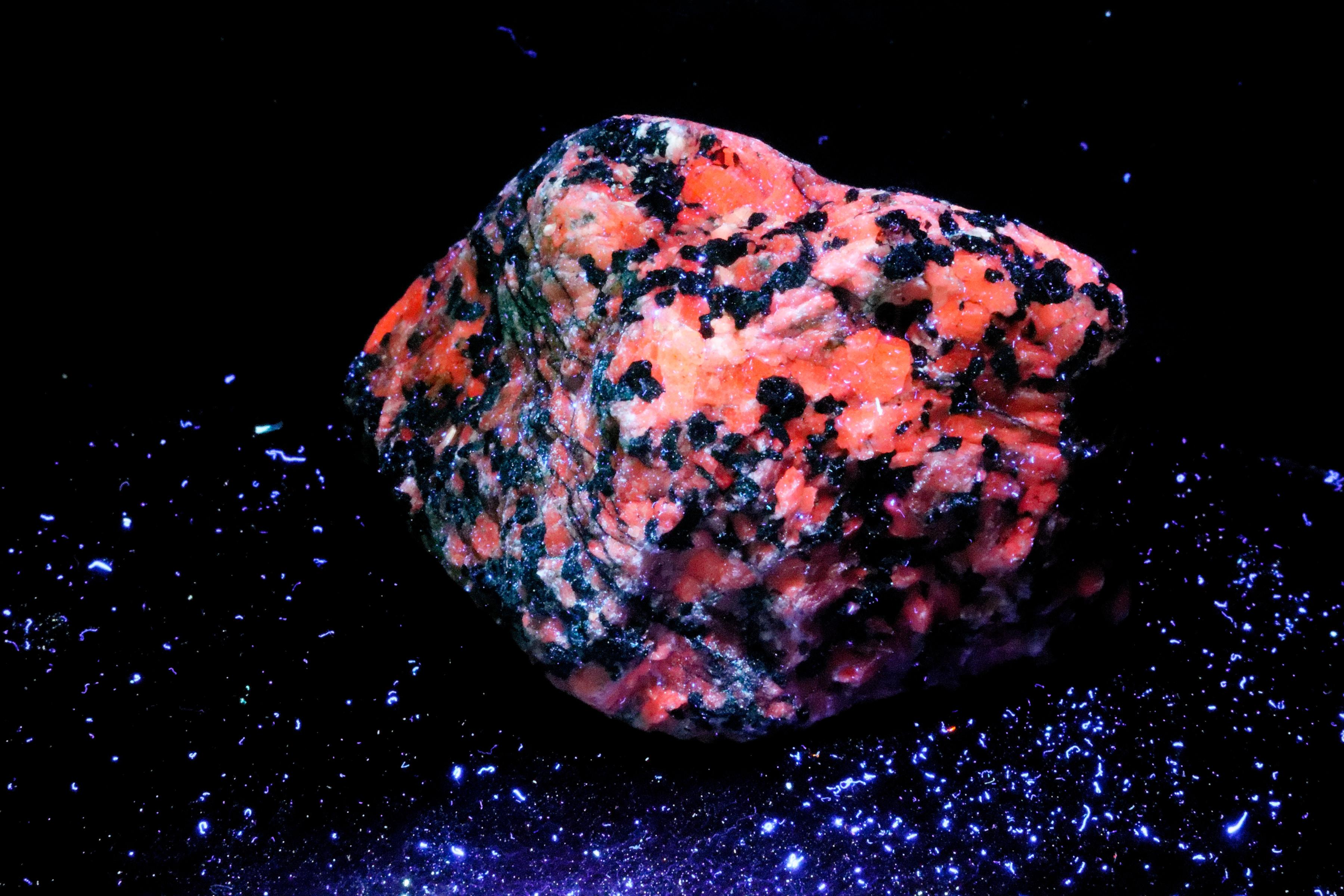
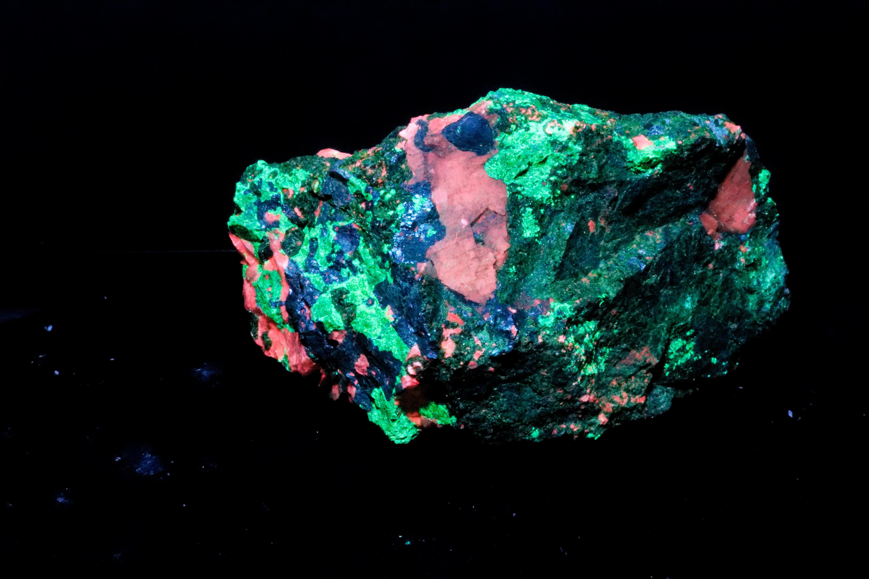
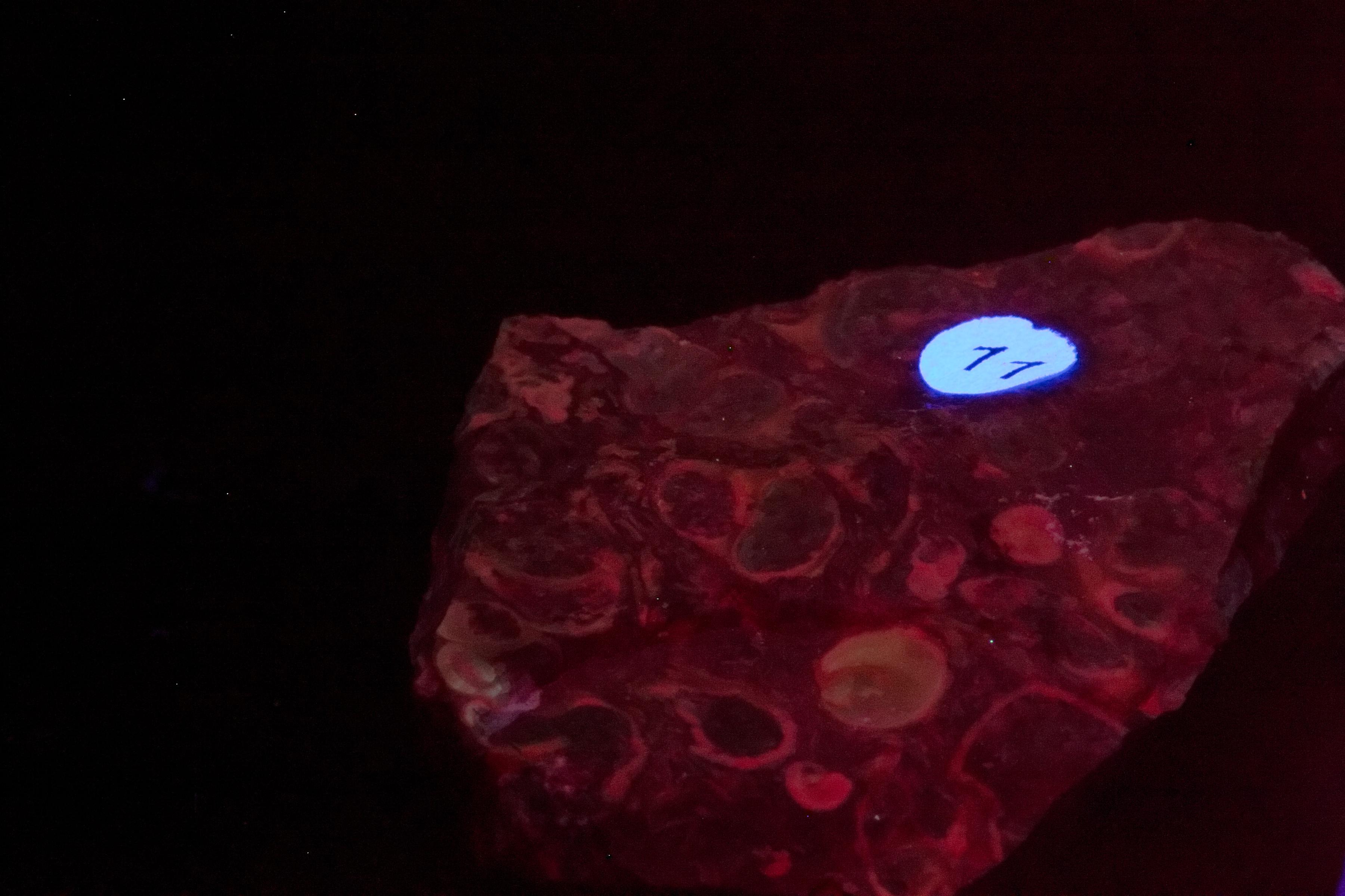
356nm
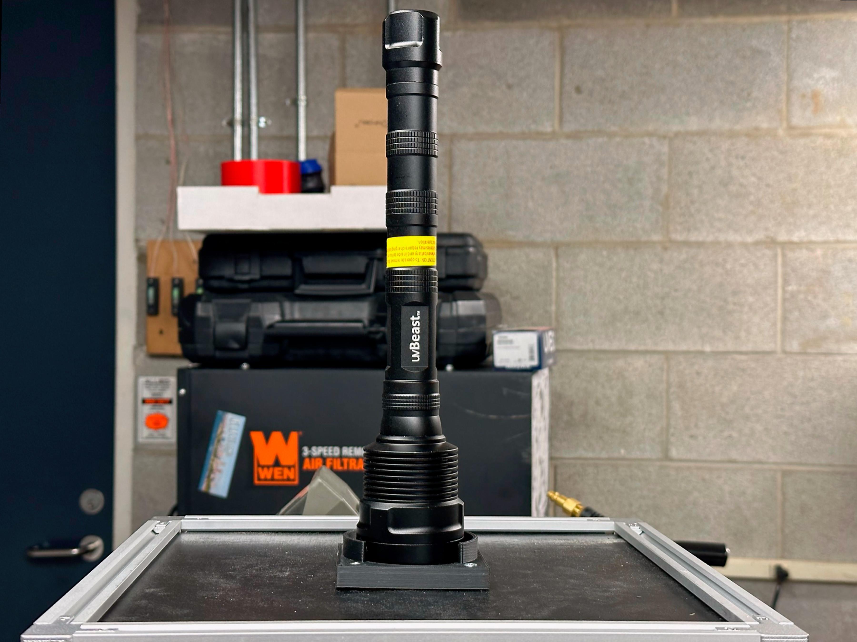
We had initially designed and produced a circuit board that used the same LEDs the flashlights listed below use. It is much easier and cheaper to use flashlights. Both of the flashlights listed have a bandpass filter element built in. The flashlights can be taken with you in the field when you hunt for specimens.
UV filtered flashlights we used:
The mount for the lamp holder can be found at Printable or Thingiverse.
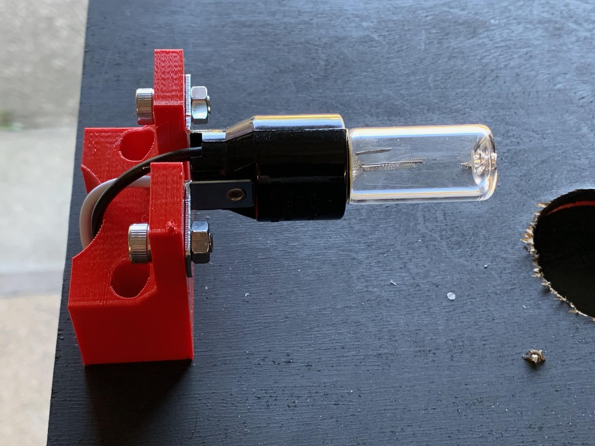
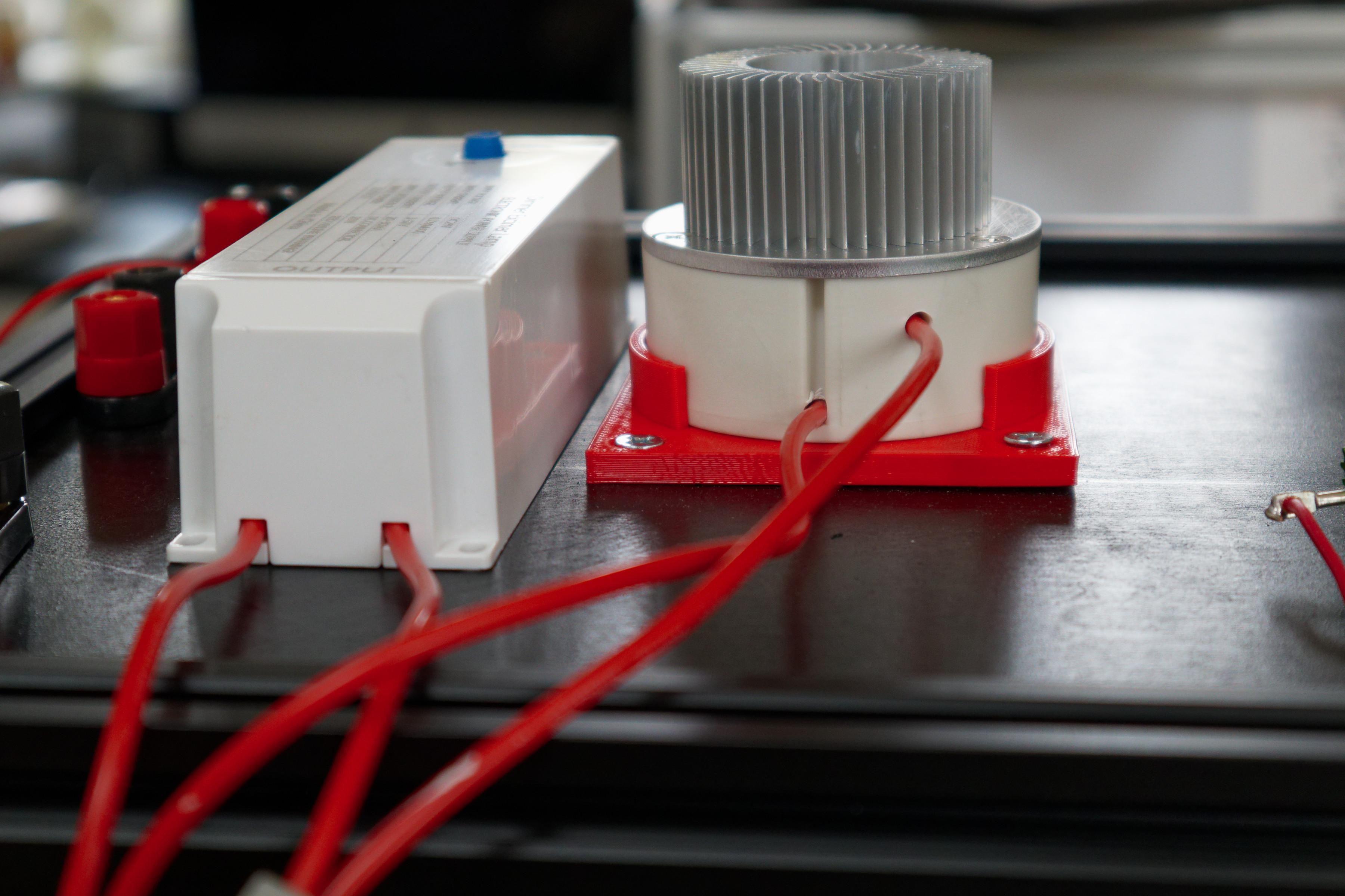
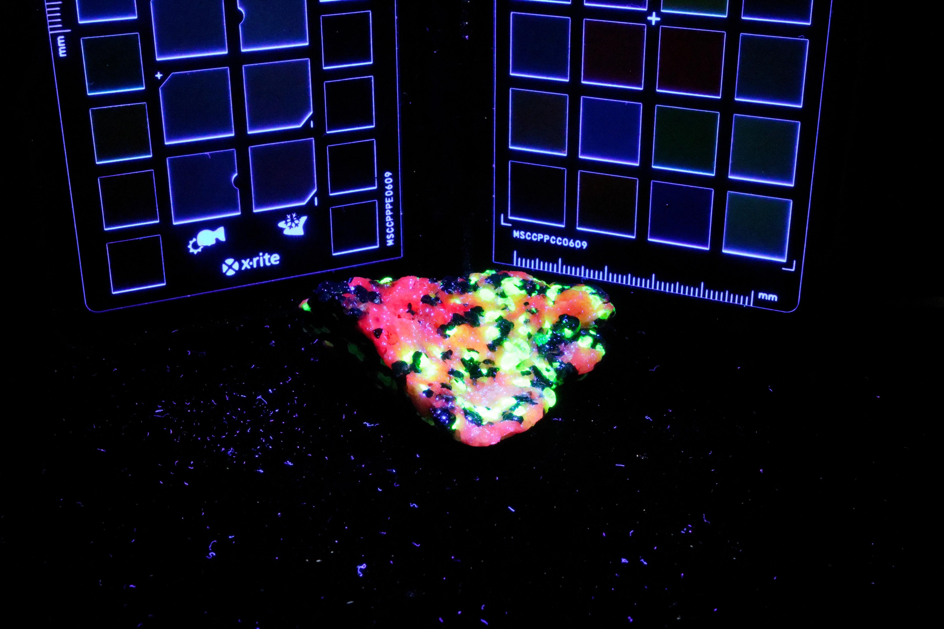
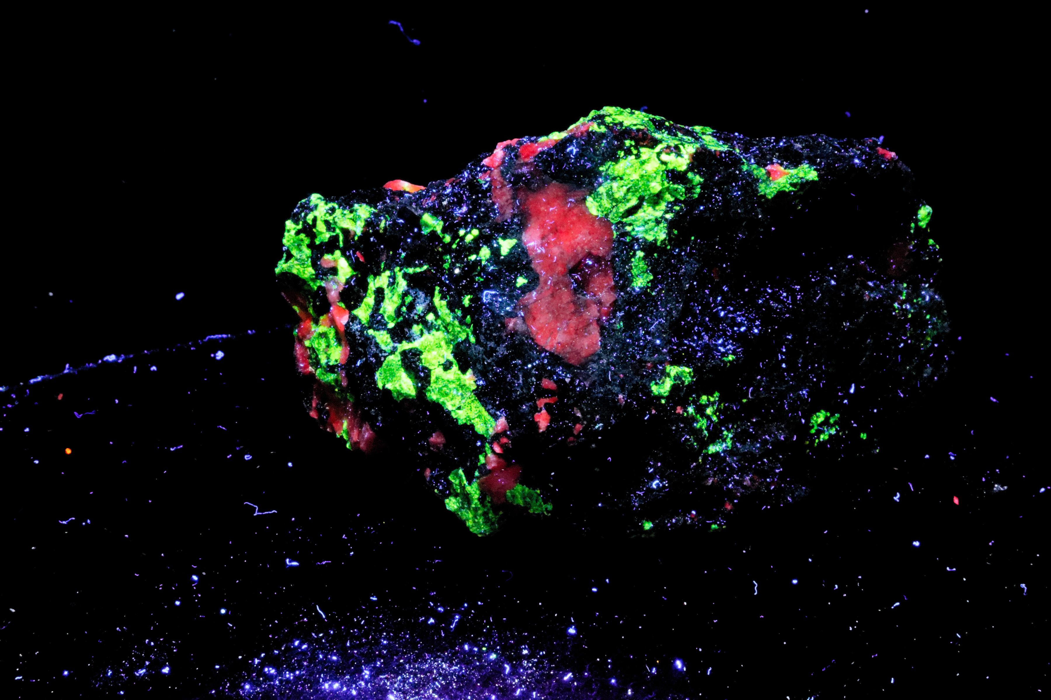
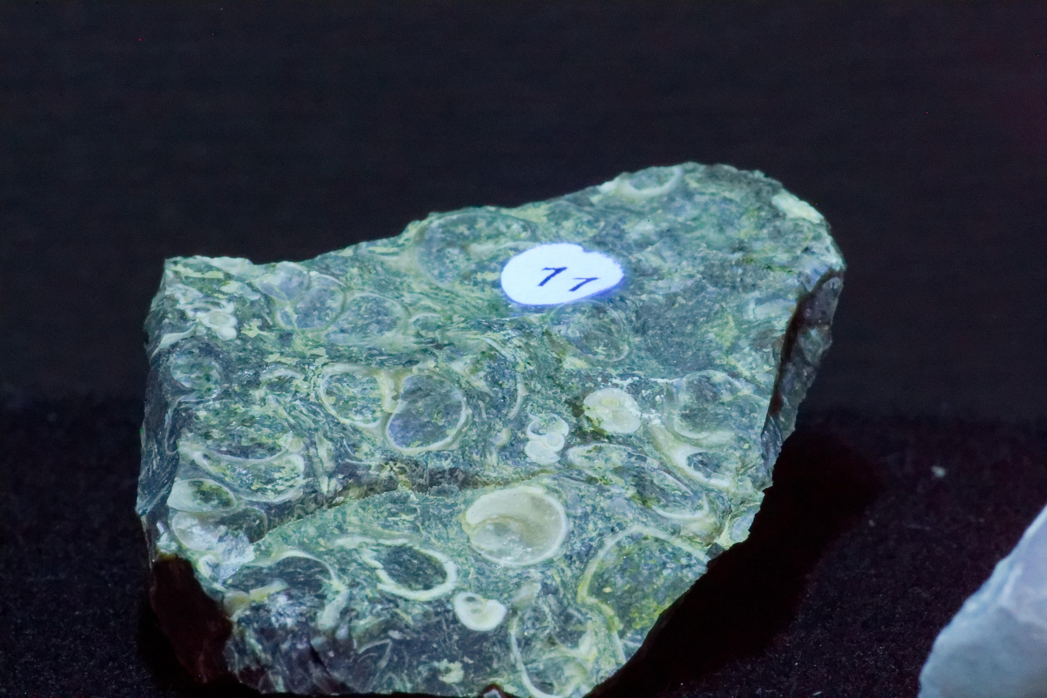
256nm
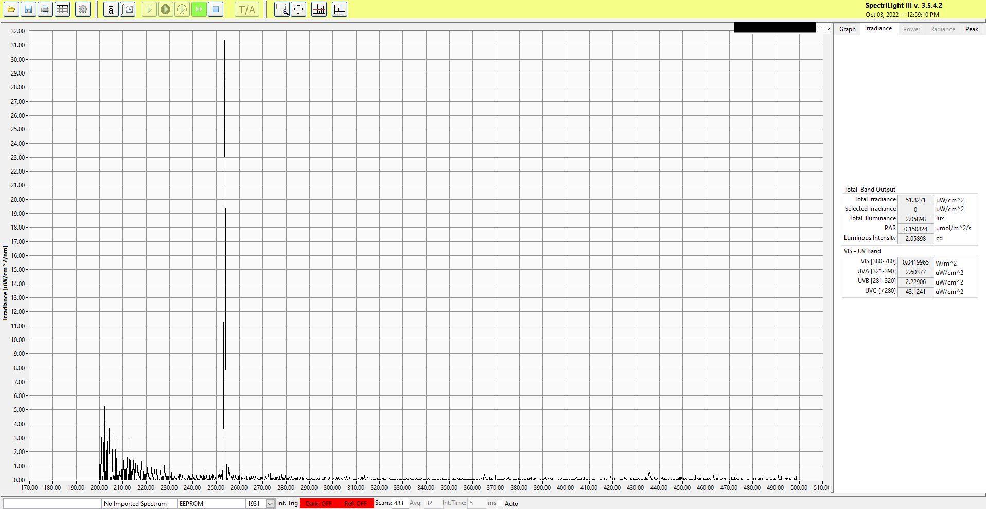
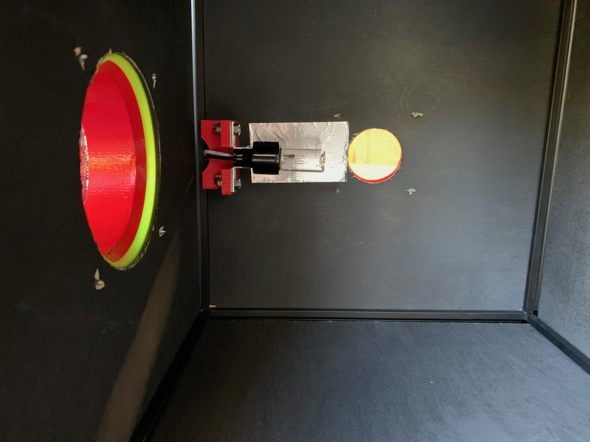
This bulb is the source of UV at 256nm. It is sold as a germicidal bulb and should be treated as dangerous. The links below will provide you with an explanation of the physics of the bulb and a simple circuit to make it work.
Resources
https://russellsrandomthoughts.blogspot.com/2013/05/the-gtl3-bulb-simple-and-inexpensive.html
https://www.instructables.com/DIY-Ultraviolet-Sterilization-Device-UVClean/
The bracket for the E17 bulb can be found on Amazon.
Search for e17 3w germicidal bulb to find the bulb.
Files for the mount for the E17 bracket can be found here: Printables or Thingiverse.
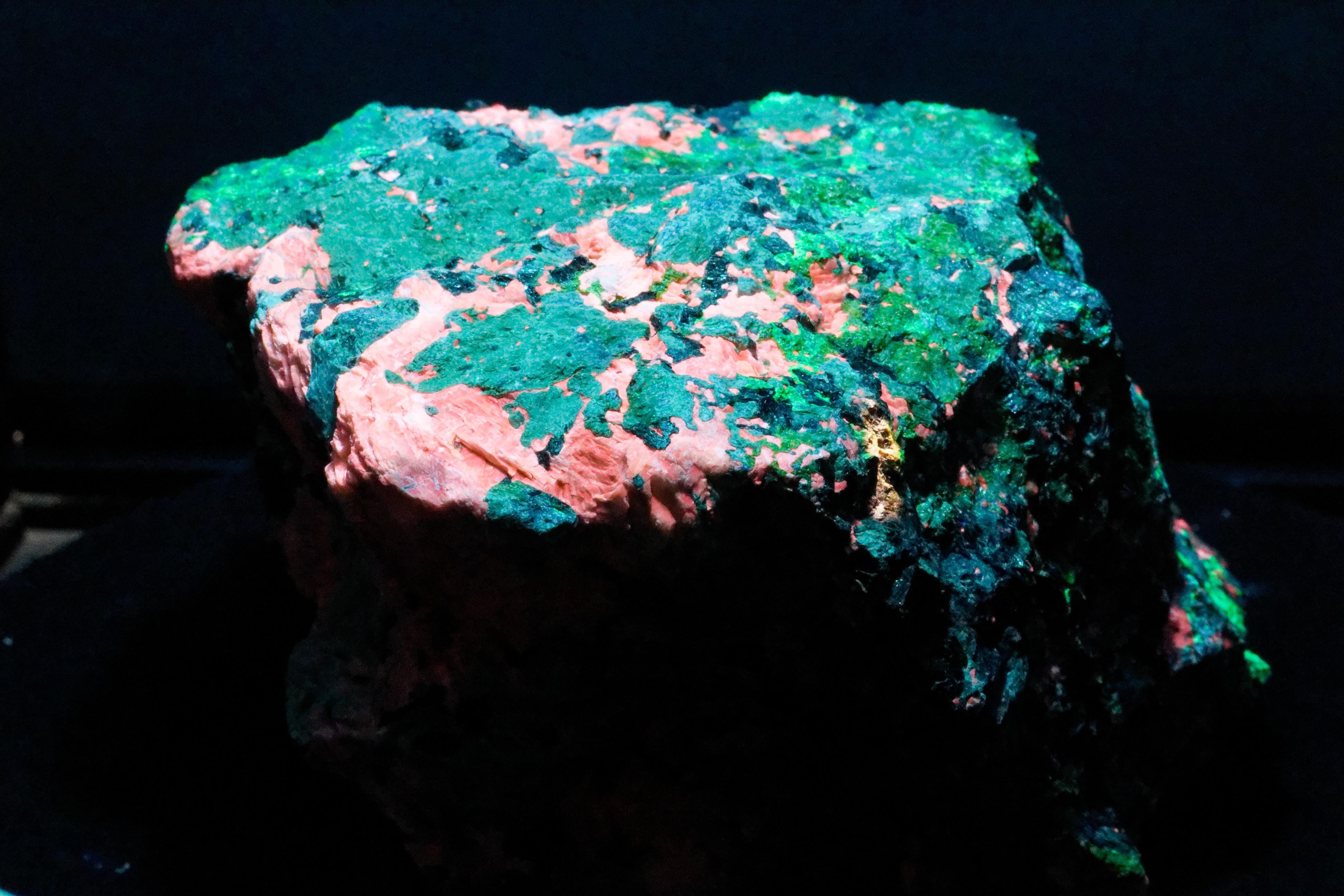
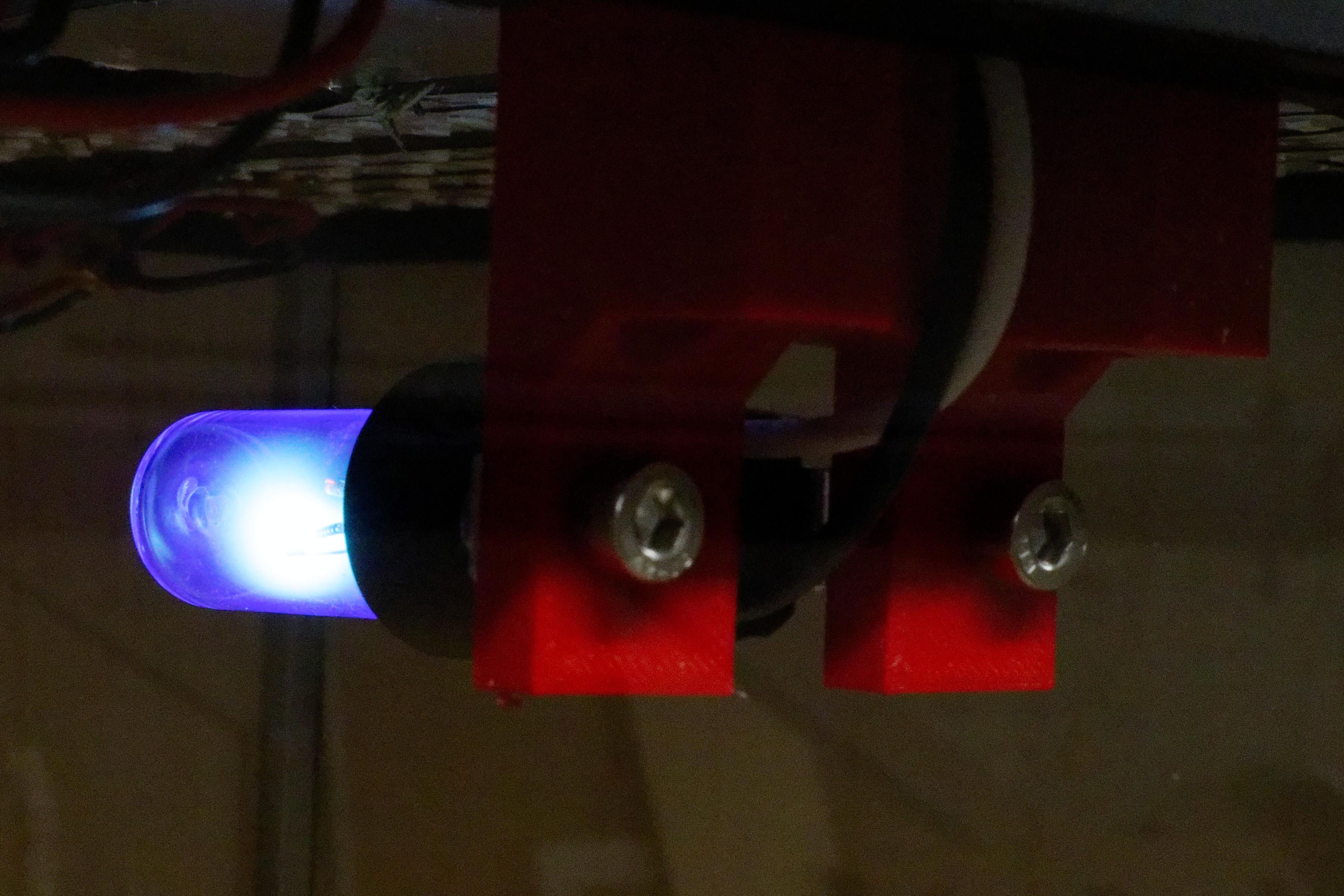
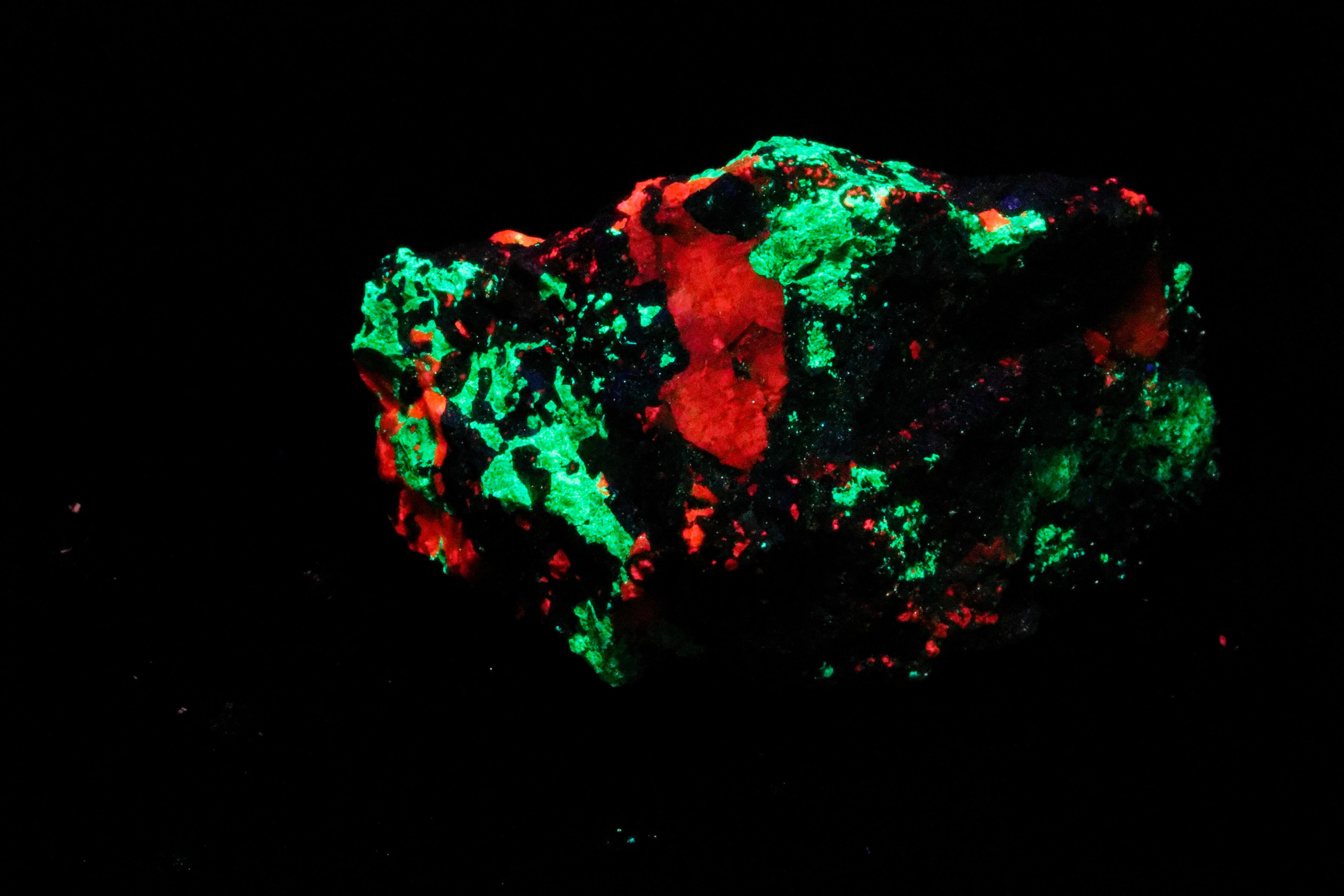
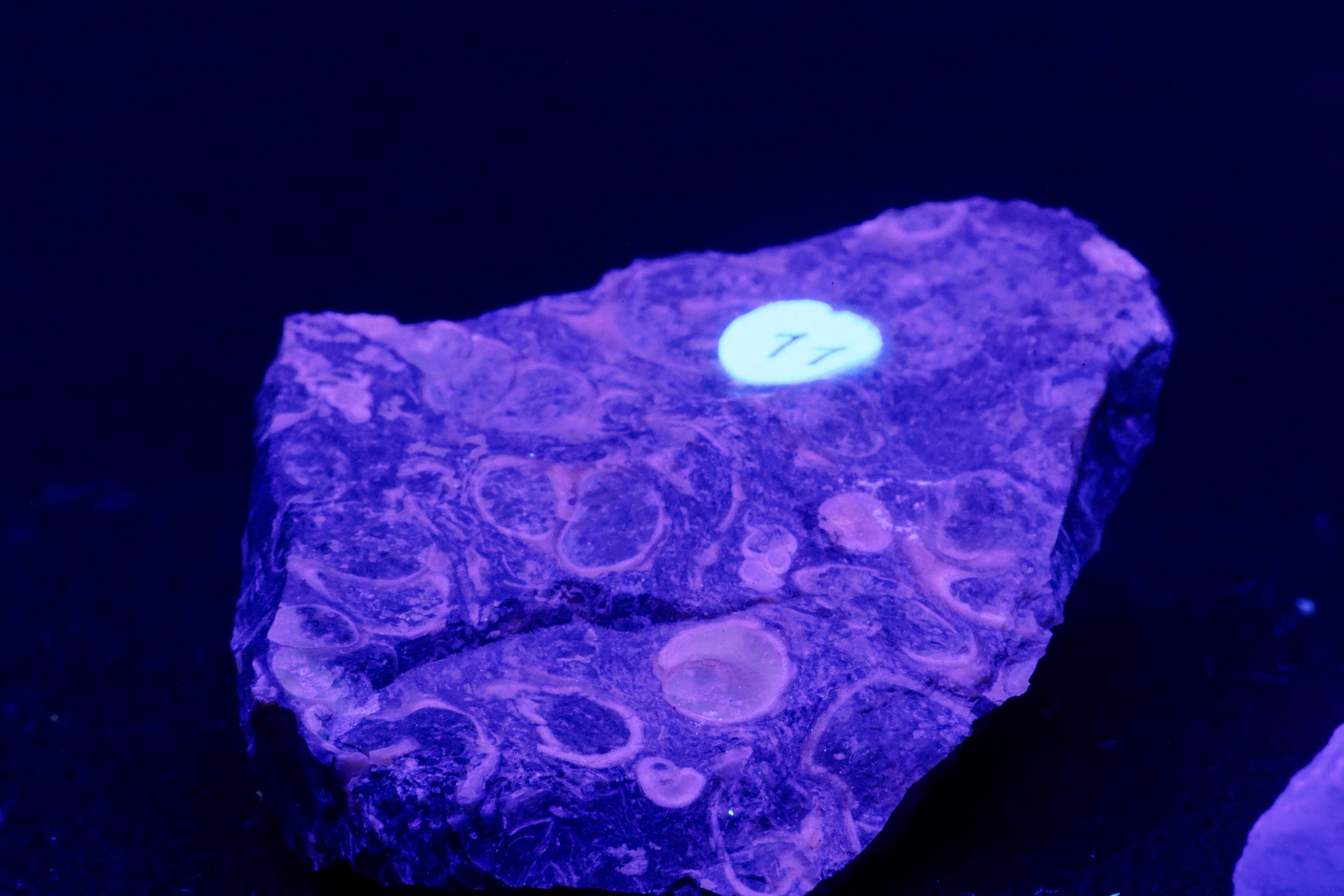
222nm
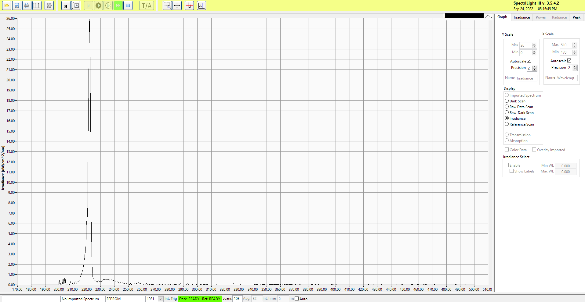
This is the lamp that started the project. While evaluating short-wave UV lamps for a project, the question is, "is there an easy way to show that the lamp is on?" The printed fluorescent plastics we used reacted to most of the UV spectrum. We remembered that certain minerals would fluoresce under different frequencies of UV light. We could show which lamp was lit by having minerals that reacted to very narrow portions of the UV spectrum.
This lame was a sample from an overseas manufacturer. The supplier we obtained it from appears to be out of business, so we can not provide a link.
Search for Excimer lamp 222nm 15w 24v A65
A little search around pays off; prices ranged from $750 down to $280 when we ran a google search in February of 2023.
This is the obligatory warning. You are buying something on the internet. The specifications that a distributor gives you may or MAY NOT be accurate. The pandemic created a Wild West marketplace for some of these products. Unless you have access to a testing lab or certified and calibrated test equipment, please err on the side of extreme caution when purchasing any UV products.
The mount for the lamp holder can be found at Printable or Thingiverse.
Safety for the First Time Use
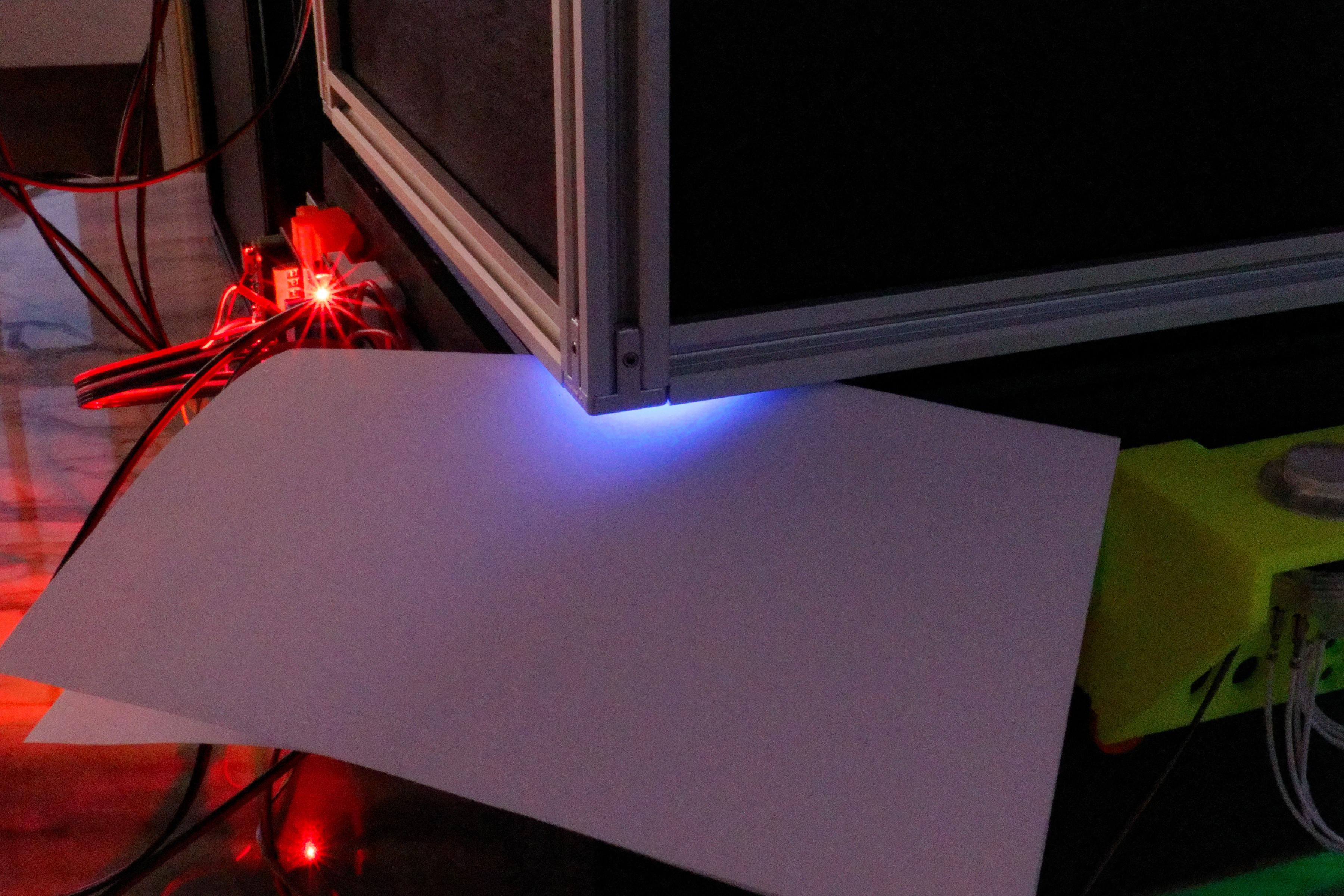
Some notes on assembling and initial testing of the dark box.
Always start testing with the highest frequency of UV light available. If you have installed the 400nm (black light), that is a great place to start. A sheet of copier paper is your best friend for setup. The "whitener" they add to copier paper is very fluorescent. It can help you track down small light leaks. Also, it is good practice to leave a sheet on the turntable when changing setups in case a UV source is accidentally active. You will not be able to see it in the presence of room light.
Light leaks work both ways. Any path UV can leak out is a path that light can leak in. While it might not impact a short exposure, it will be visible in longer exposures.
Yes, you can wear dayglow clothing too. If you or your teammates start to glow, there is a leak somewhere.
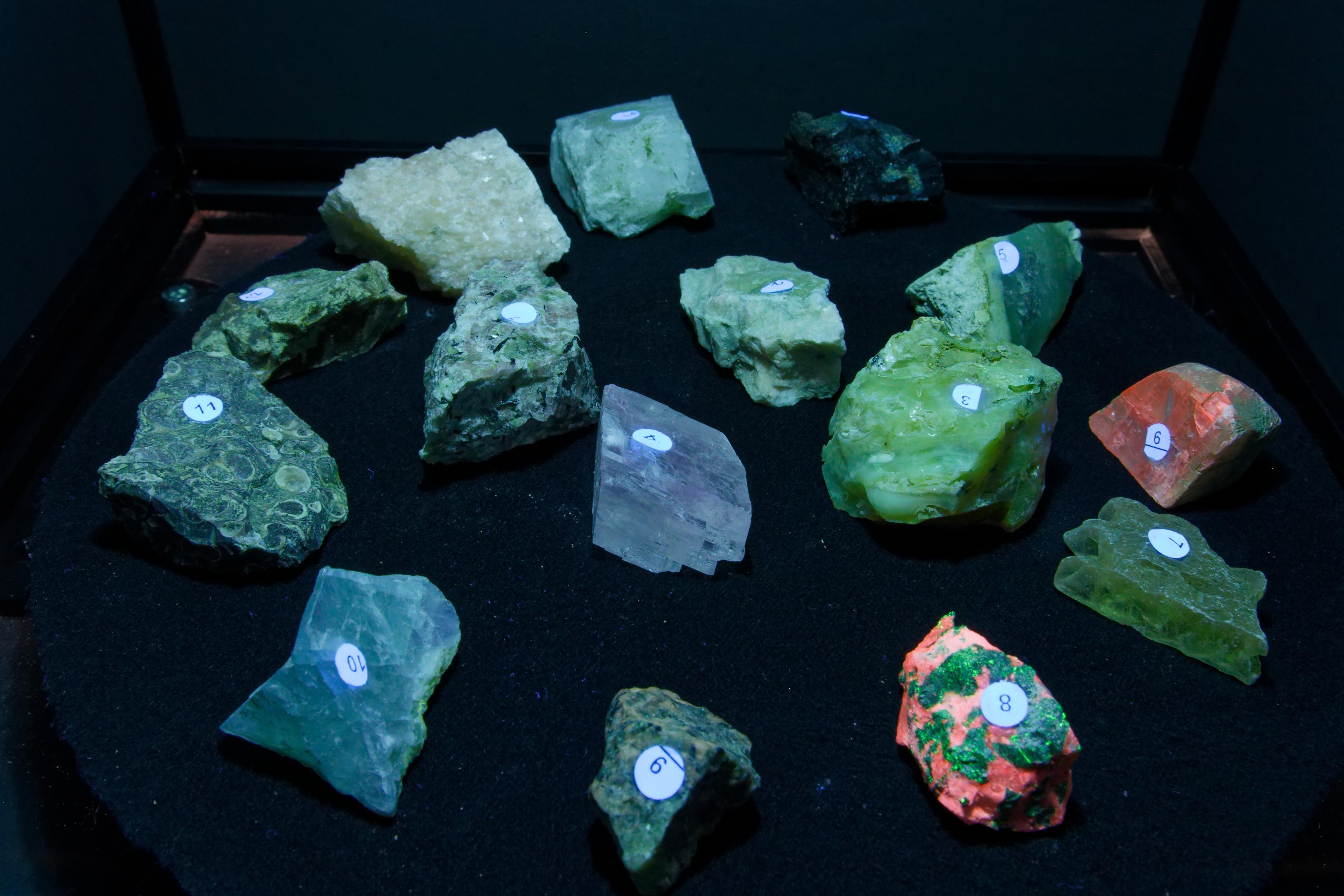
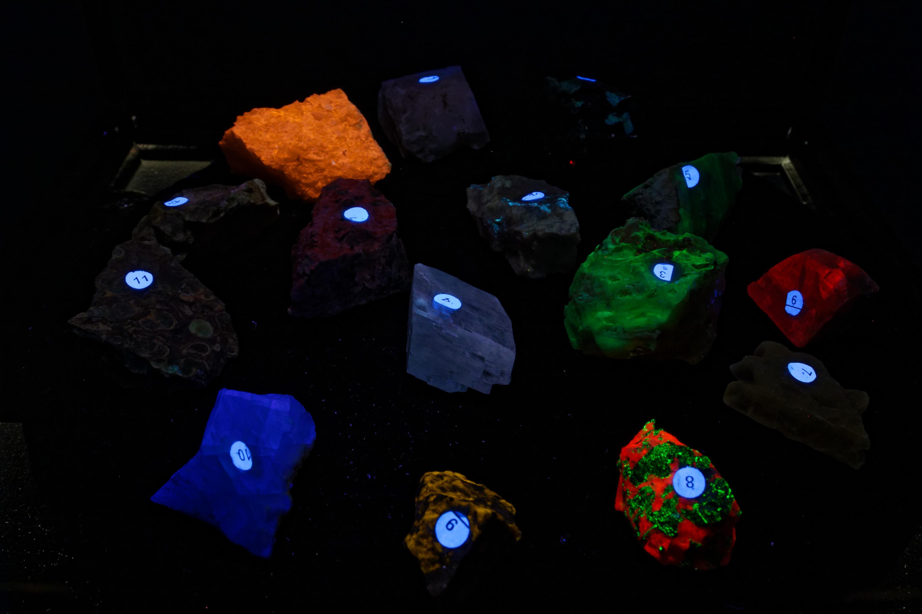
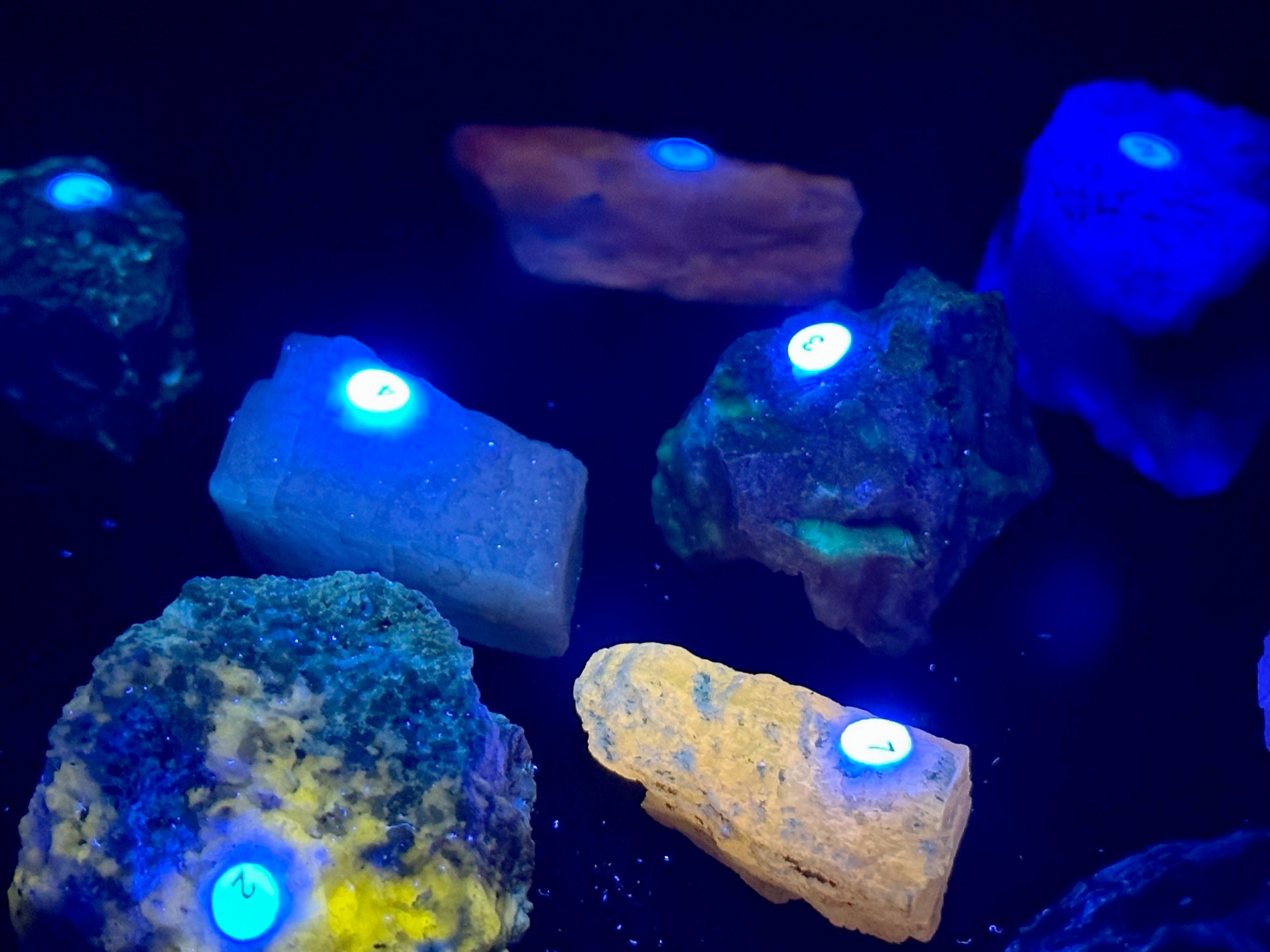
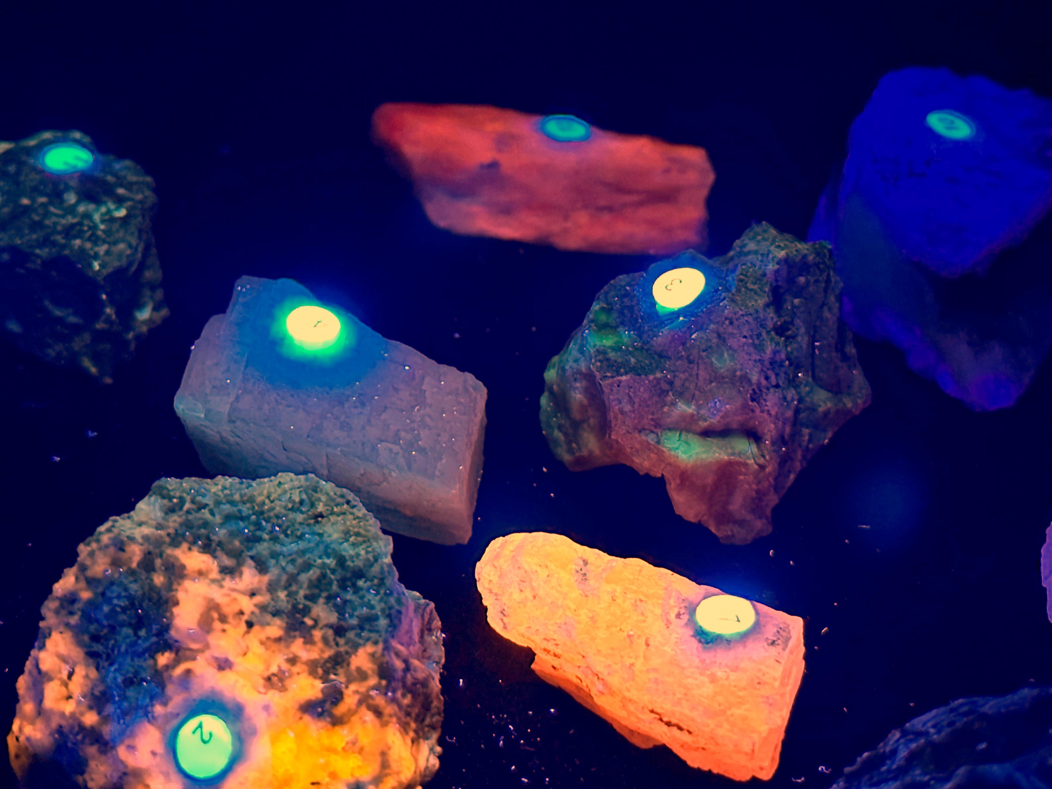
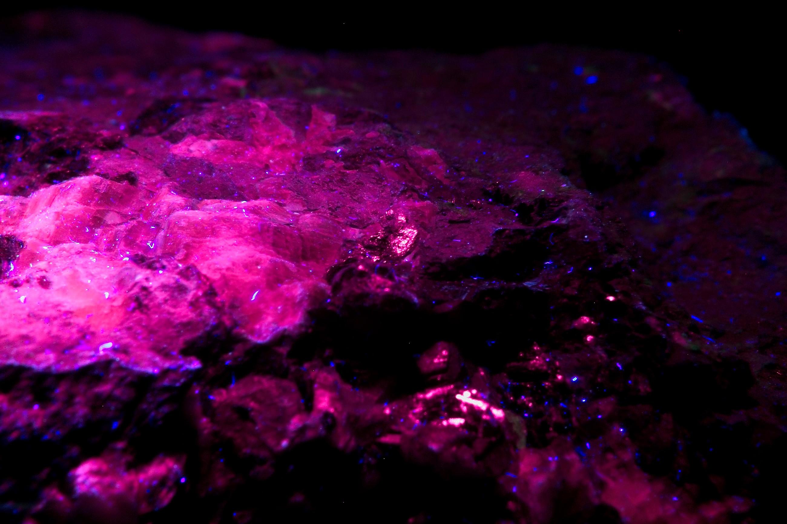
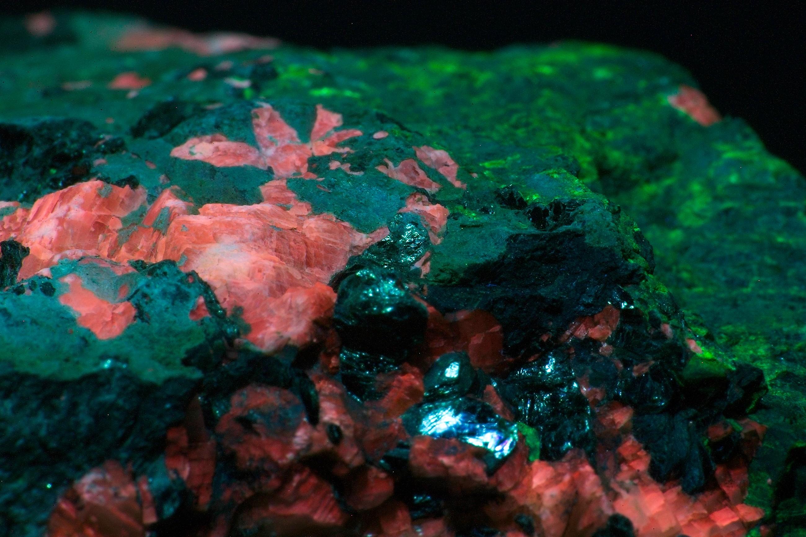
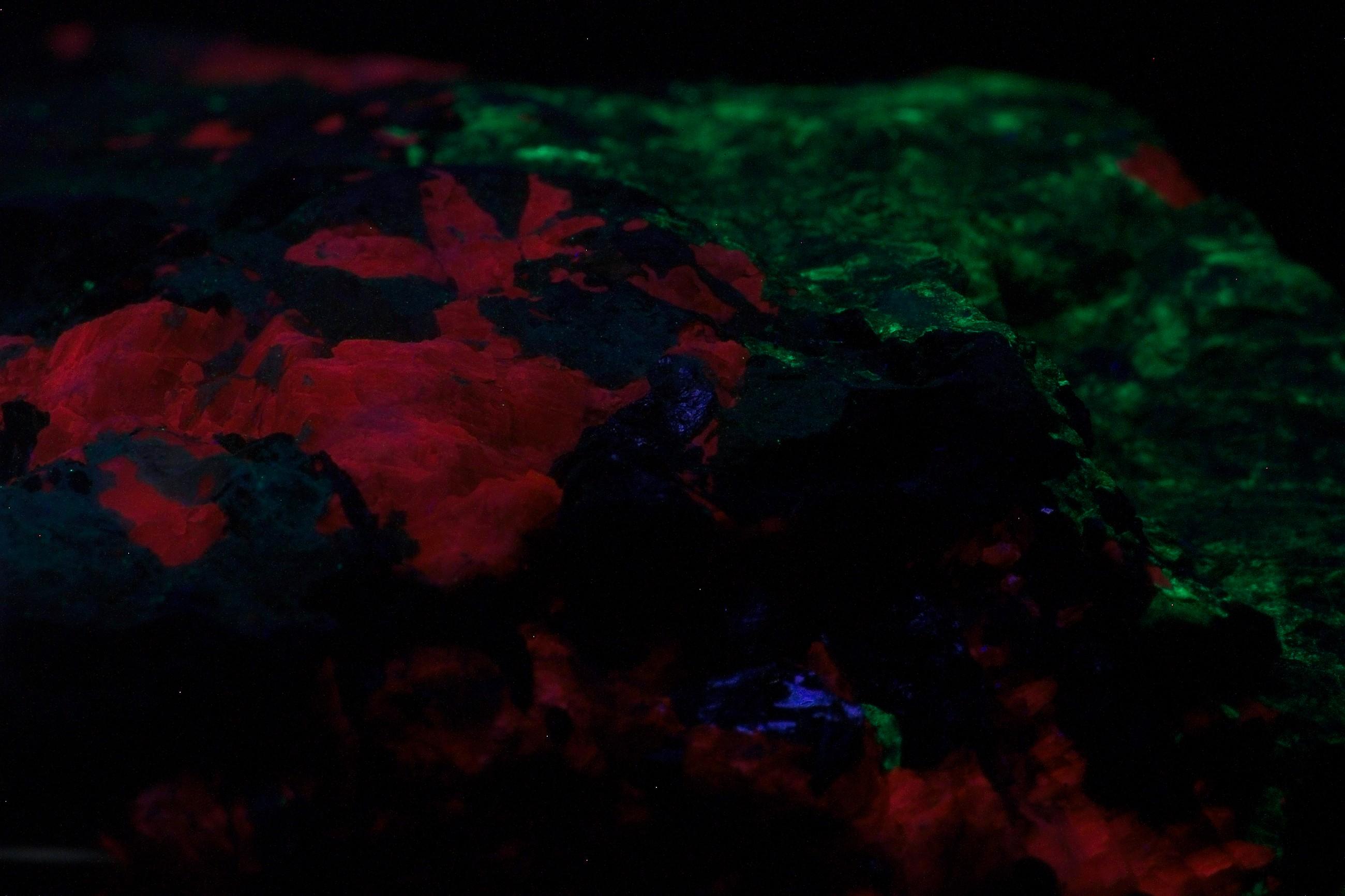
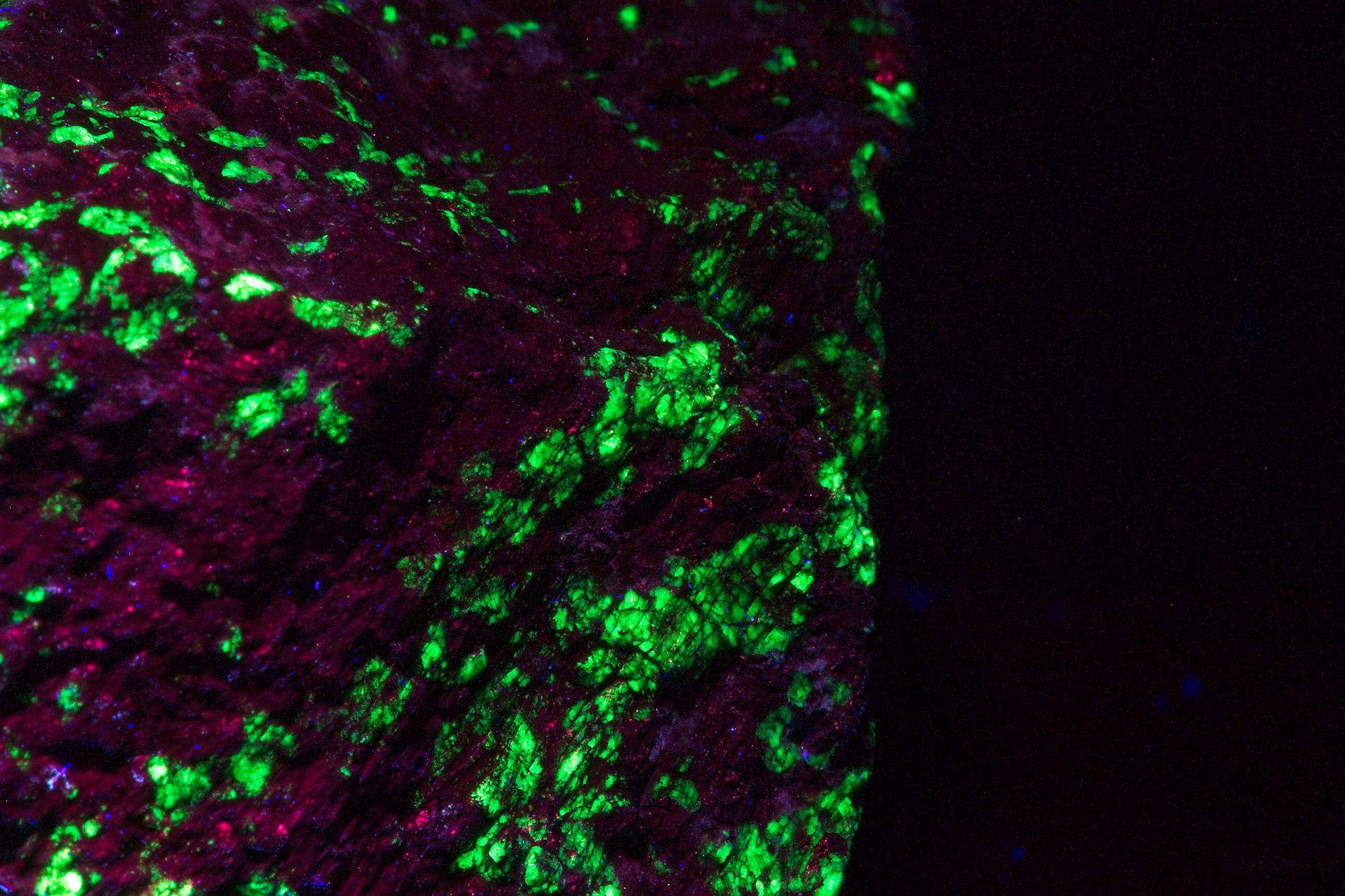
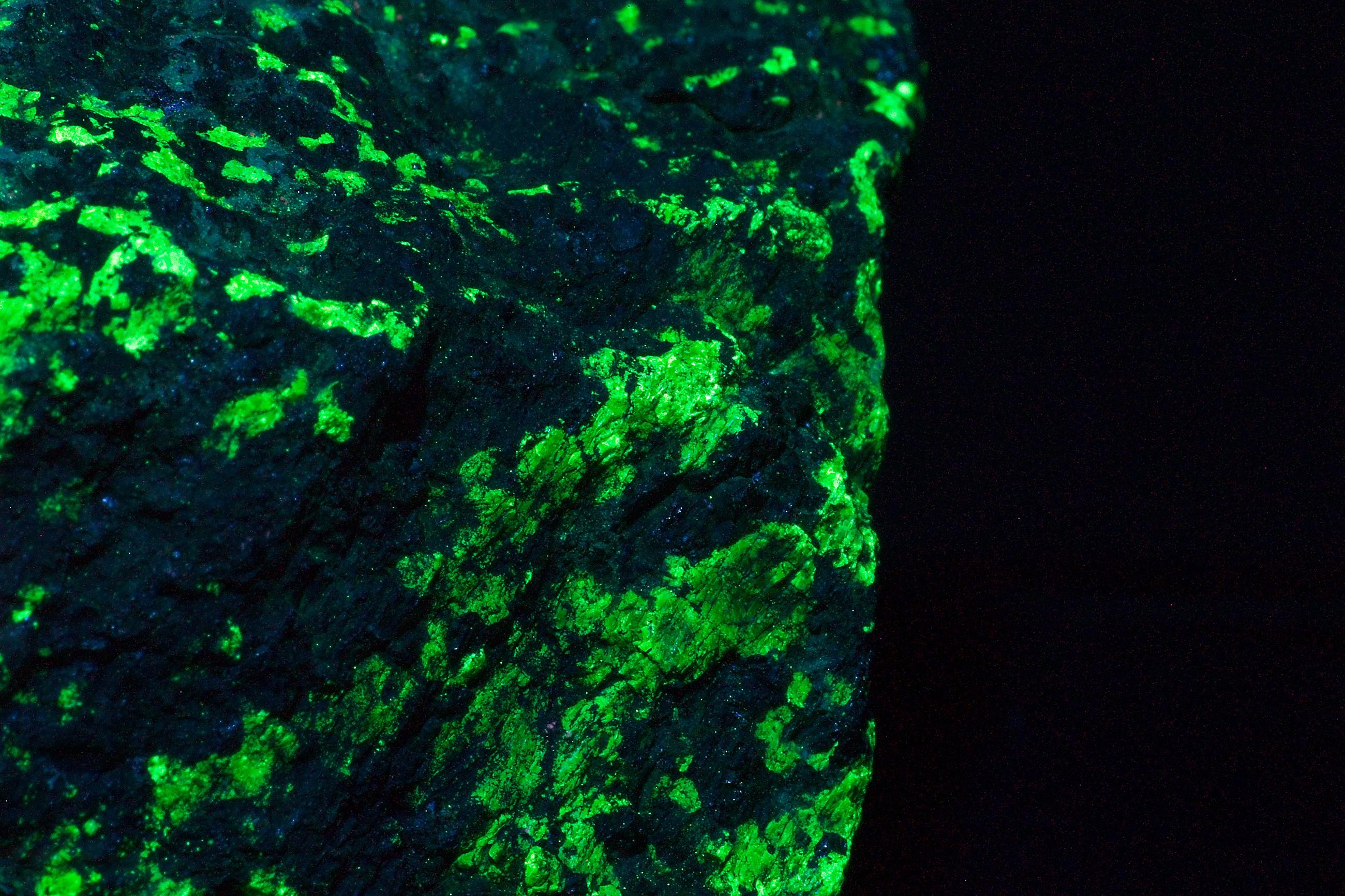
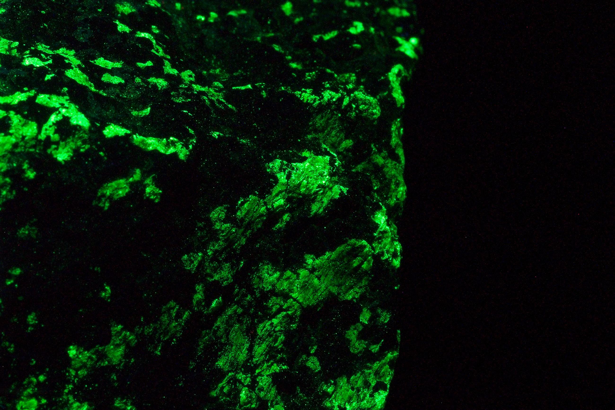
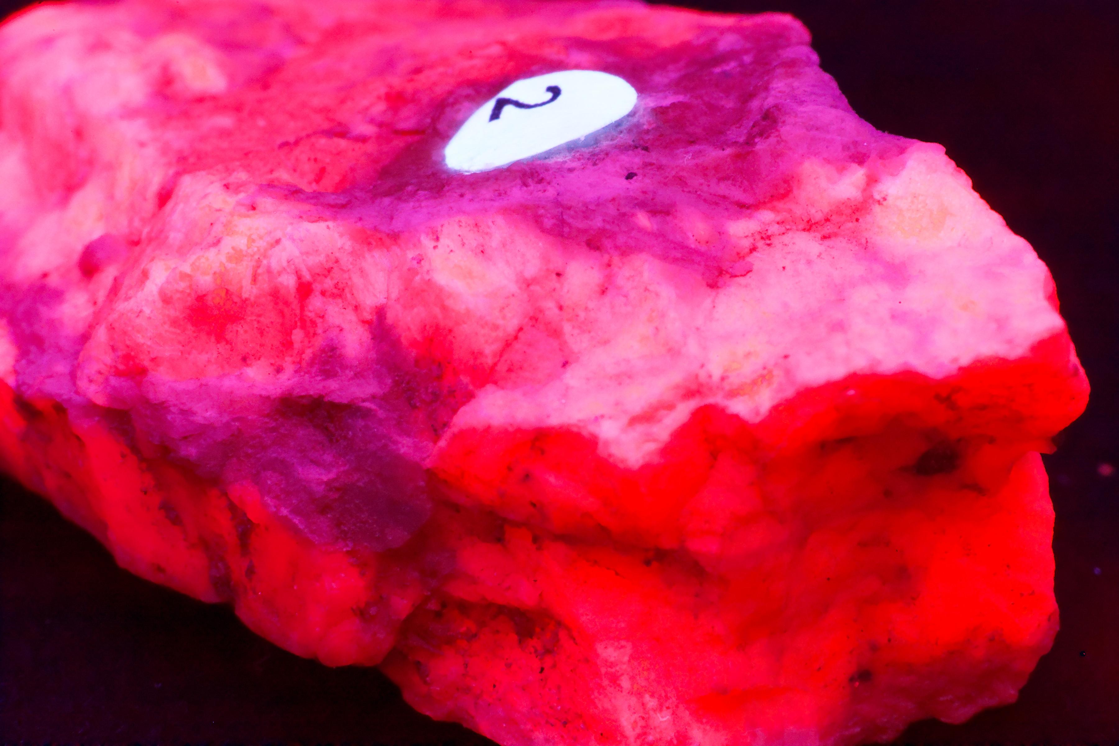
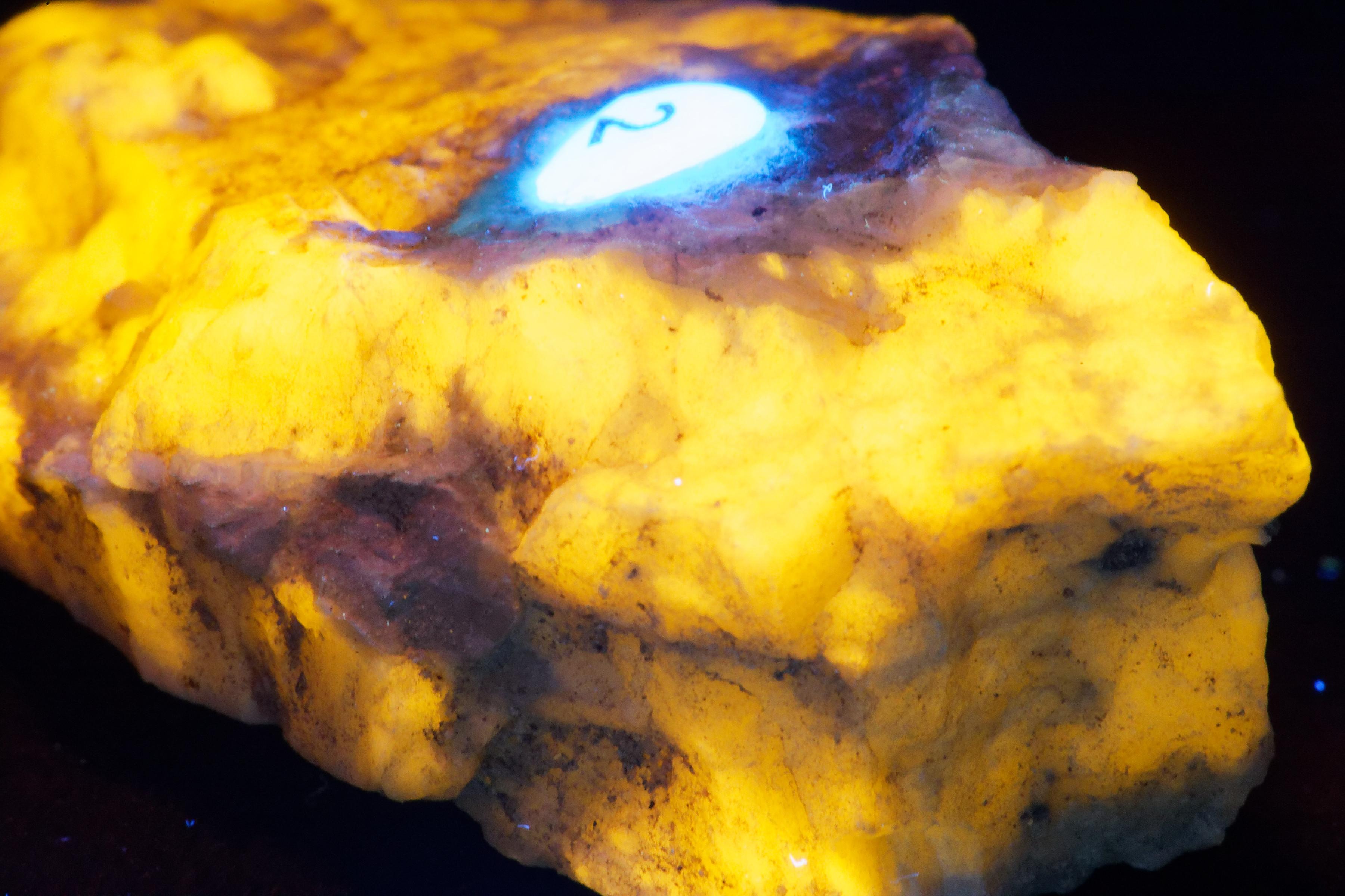
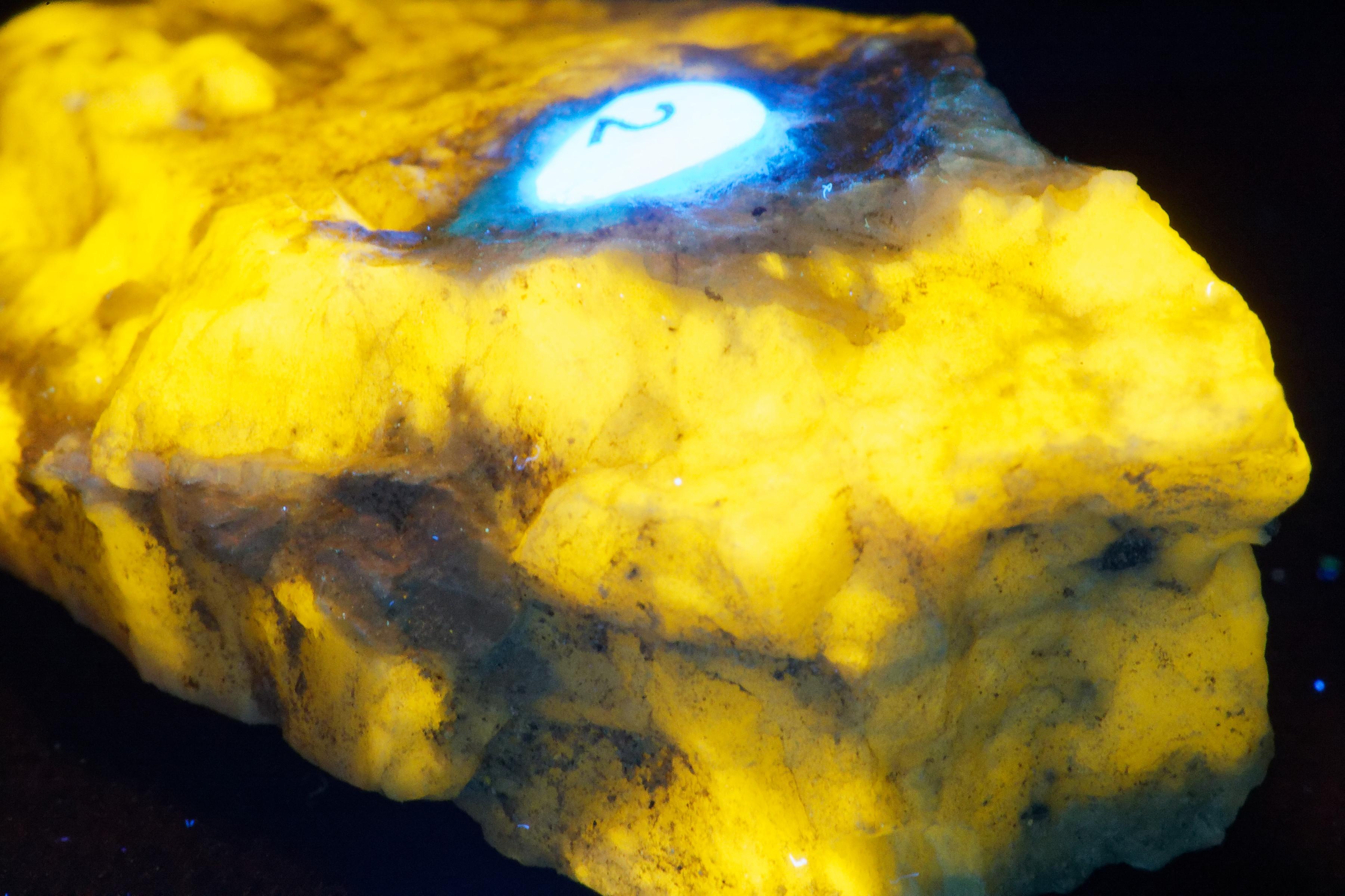
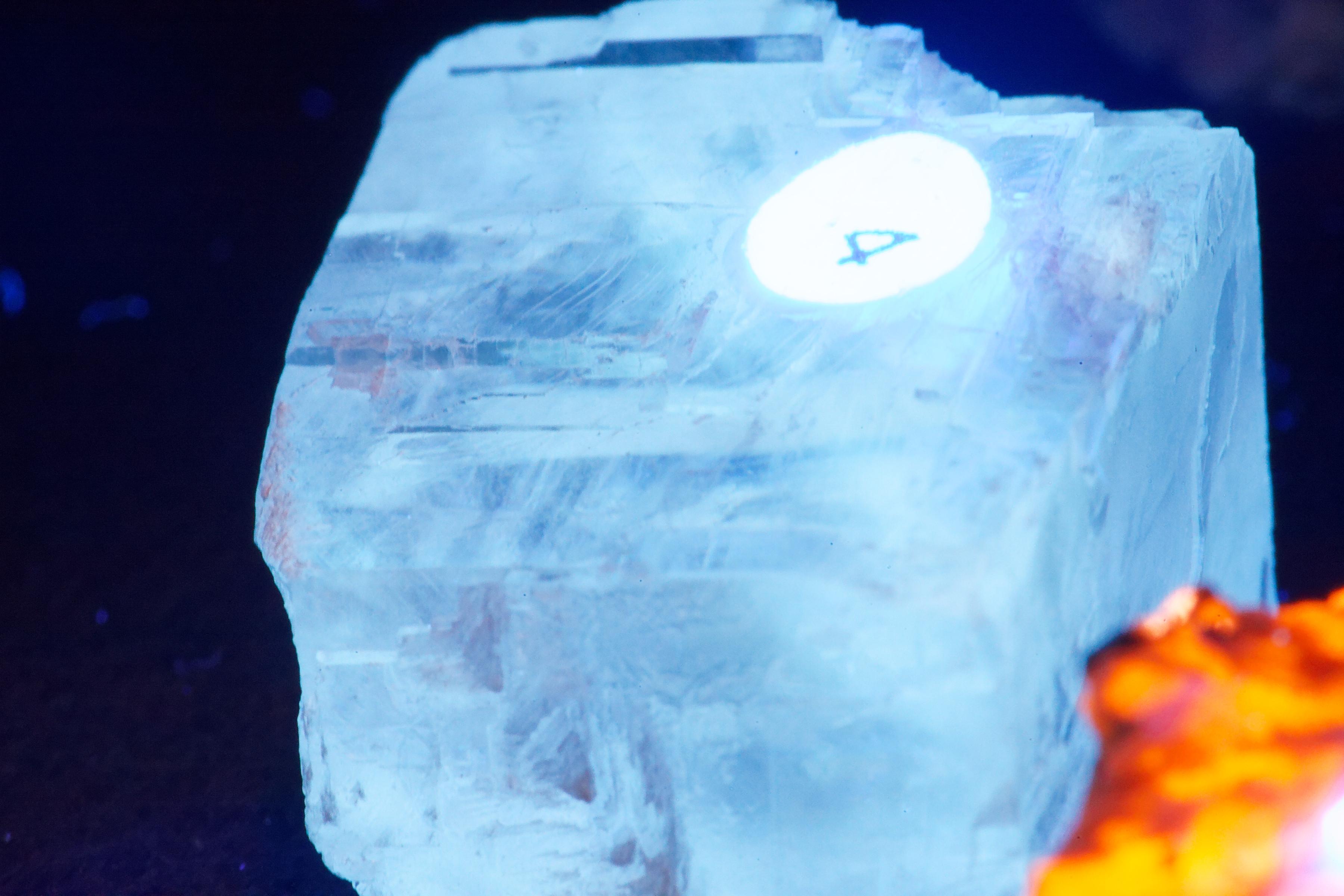
Color Corection and the Problem of White Balance in a UV Environment
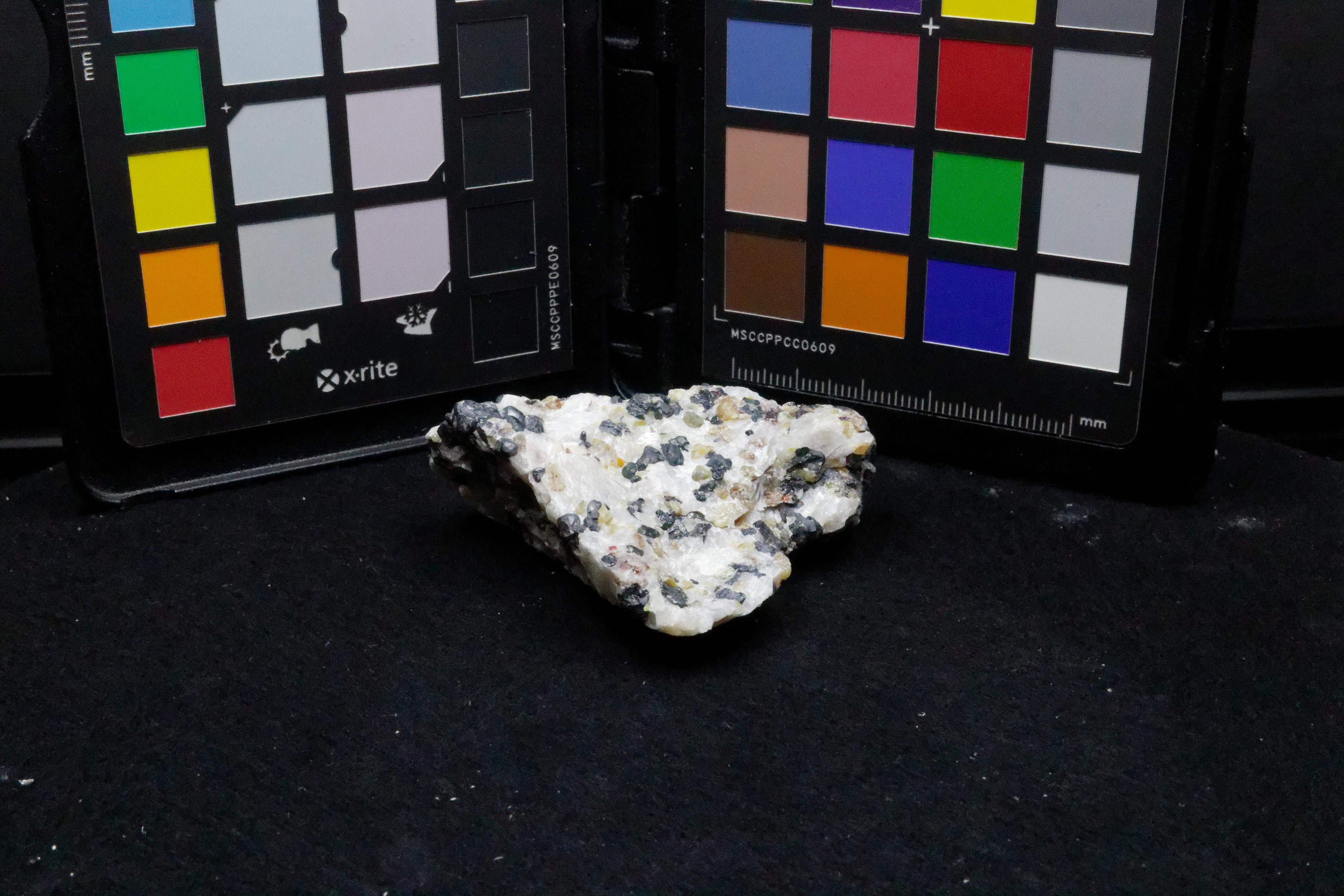
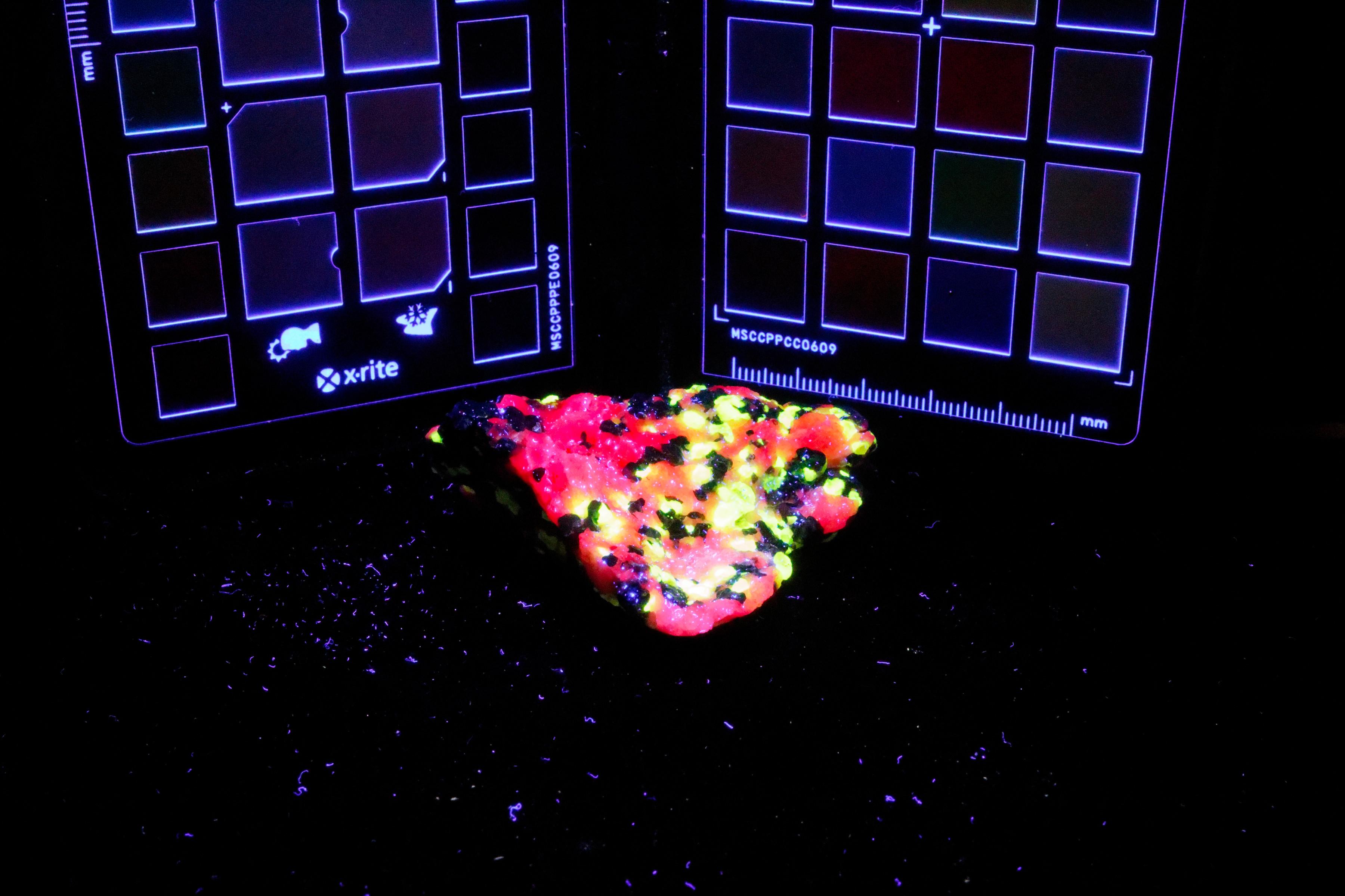
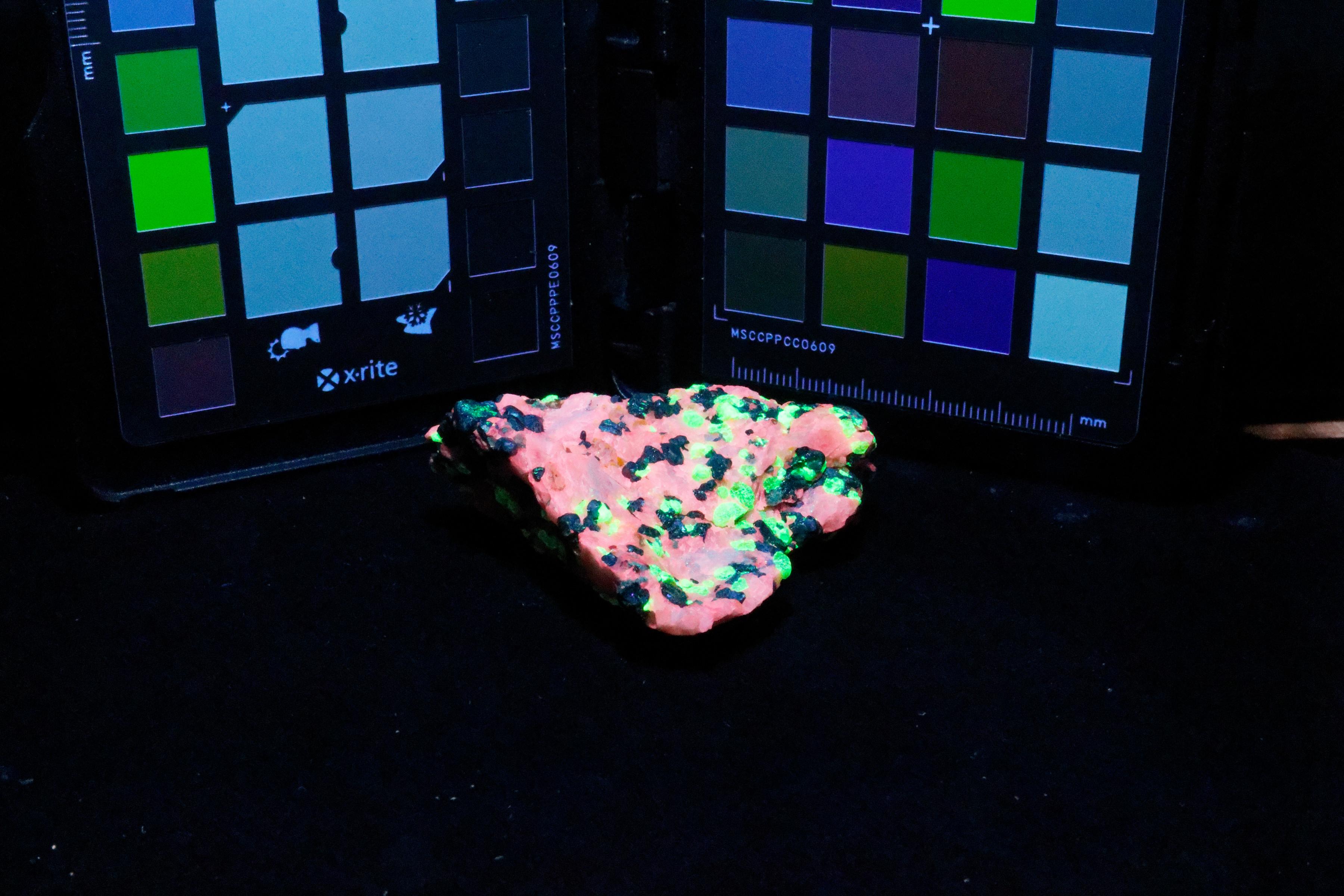
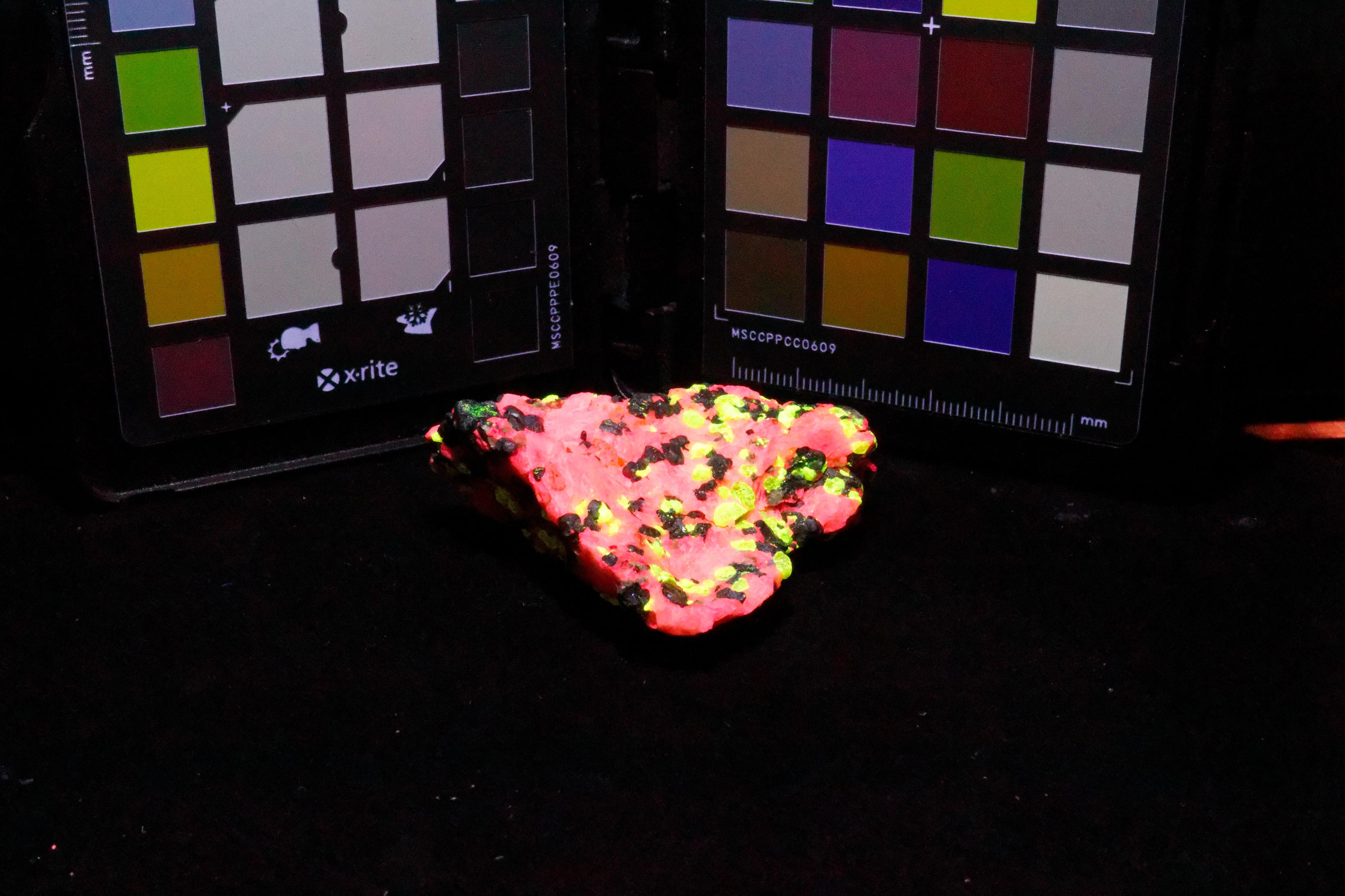
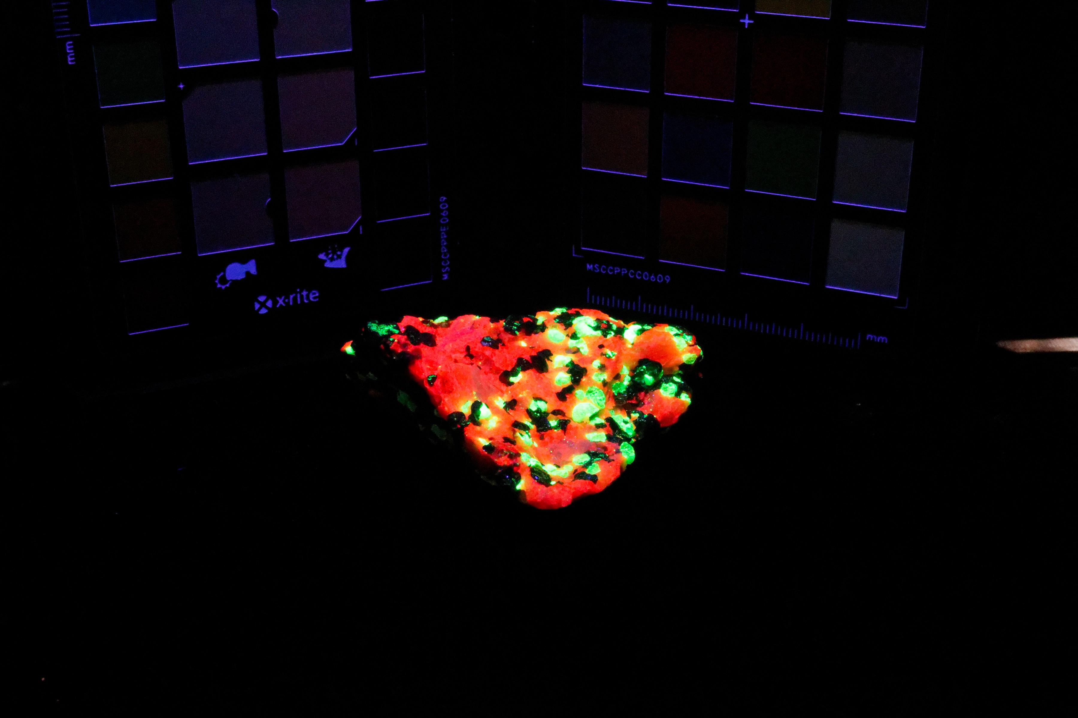
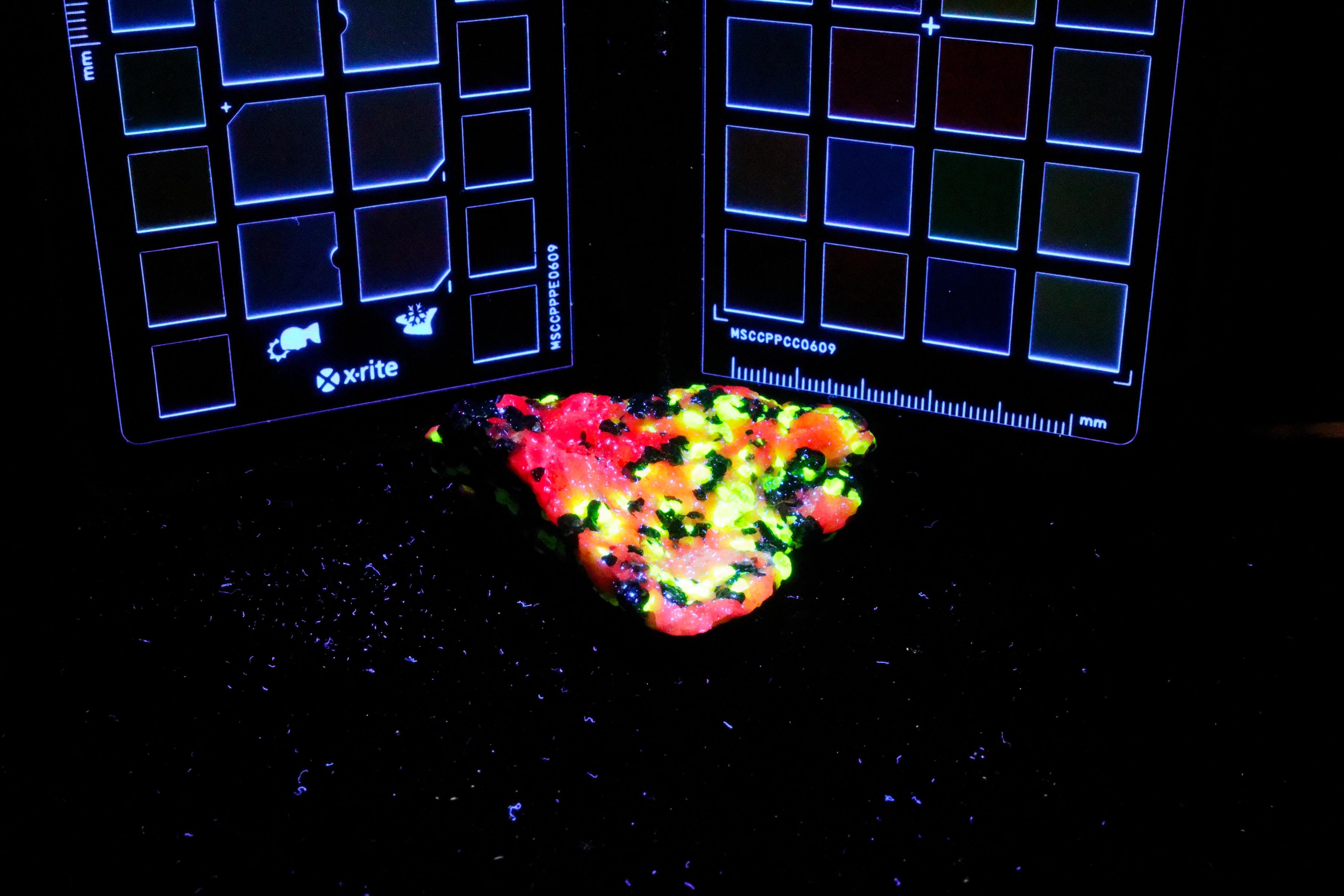
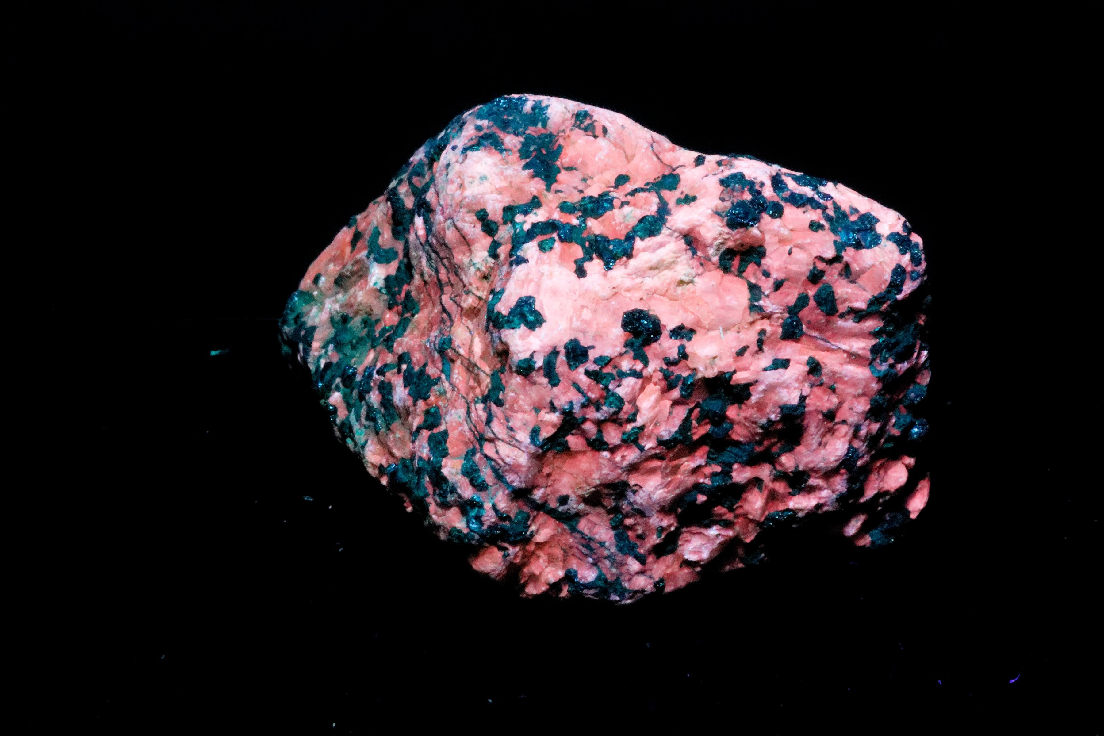
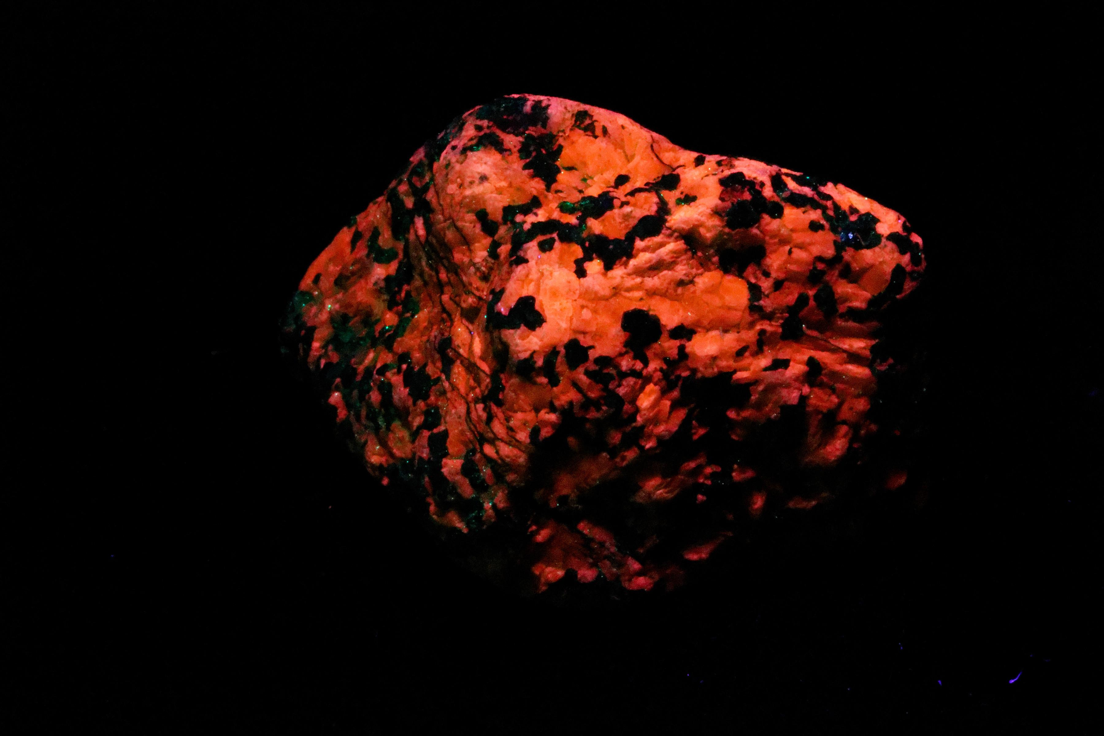
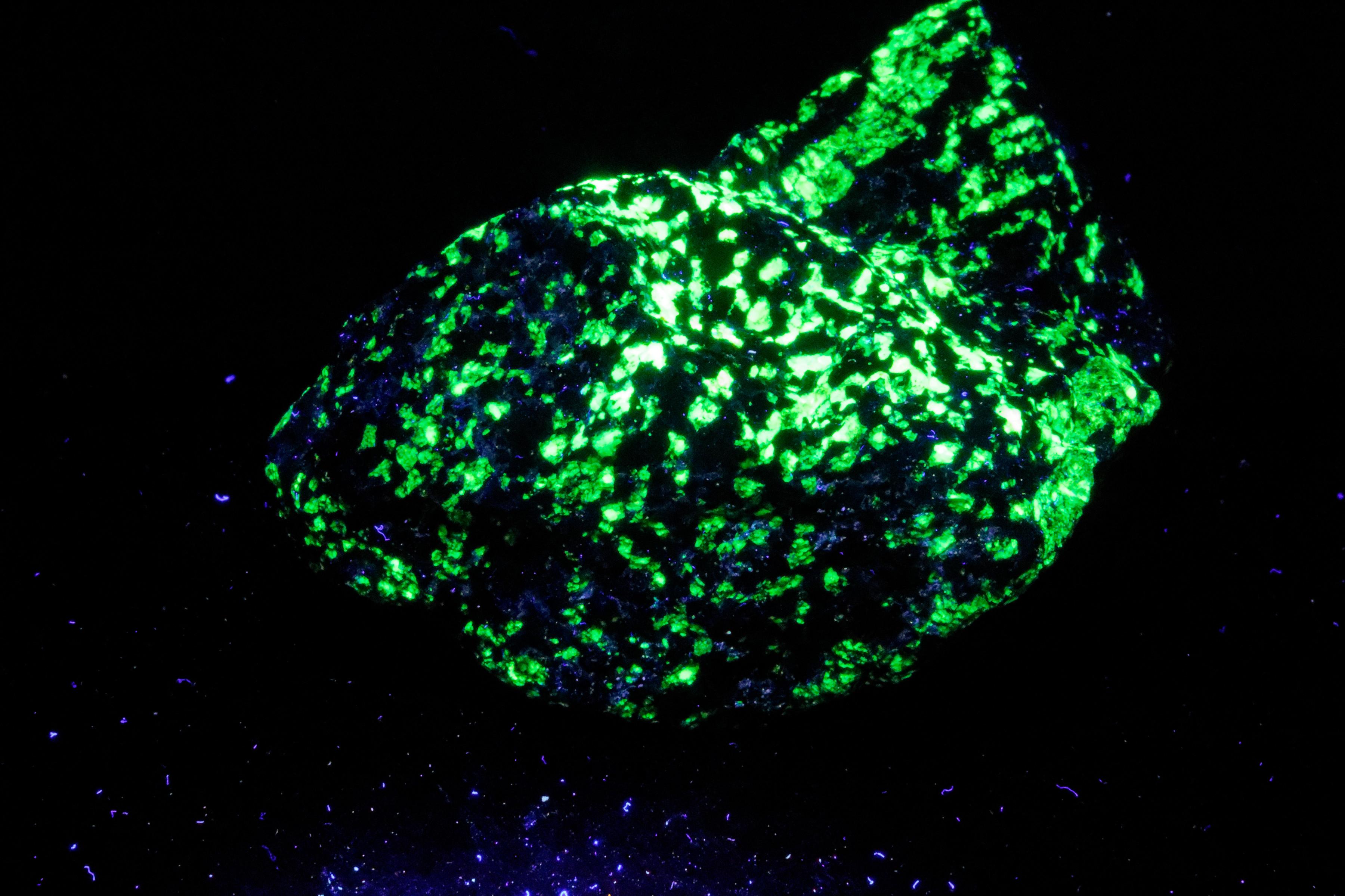
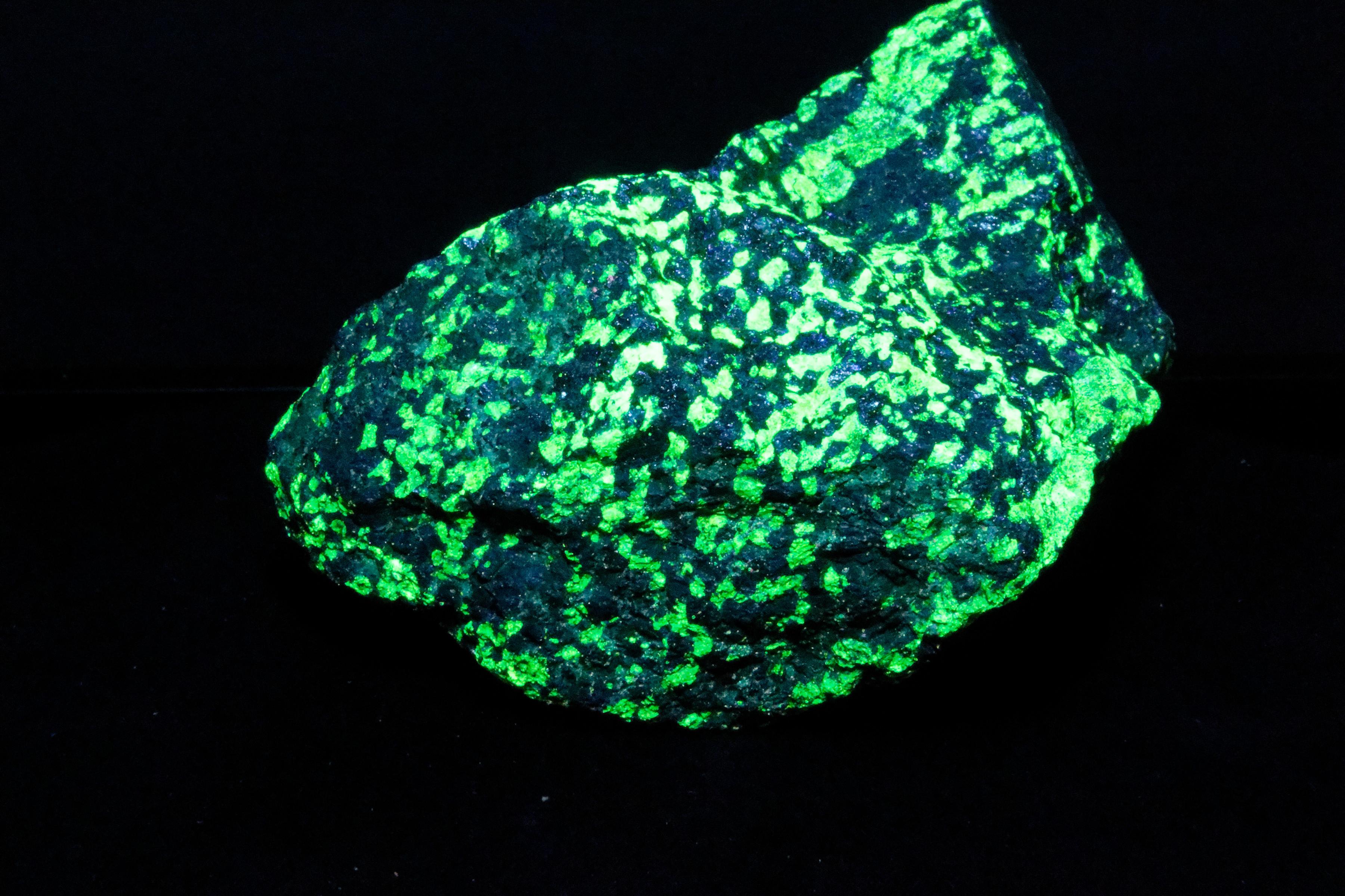
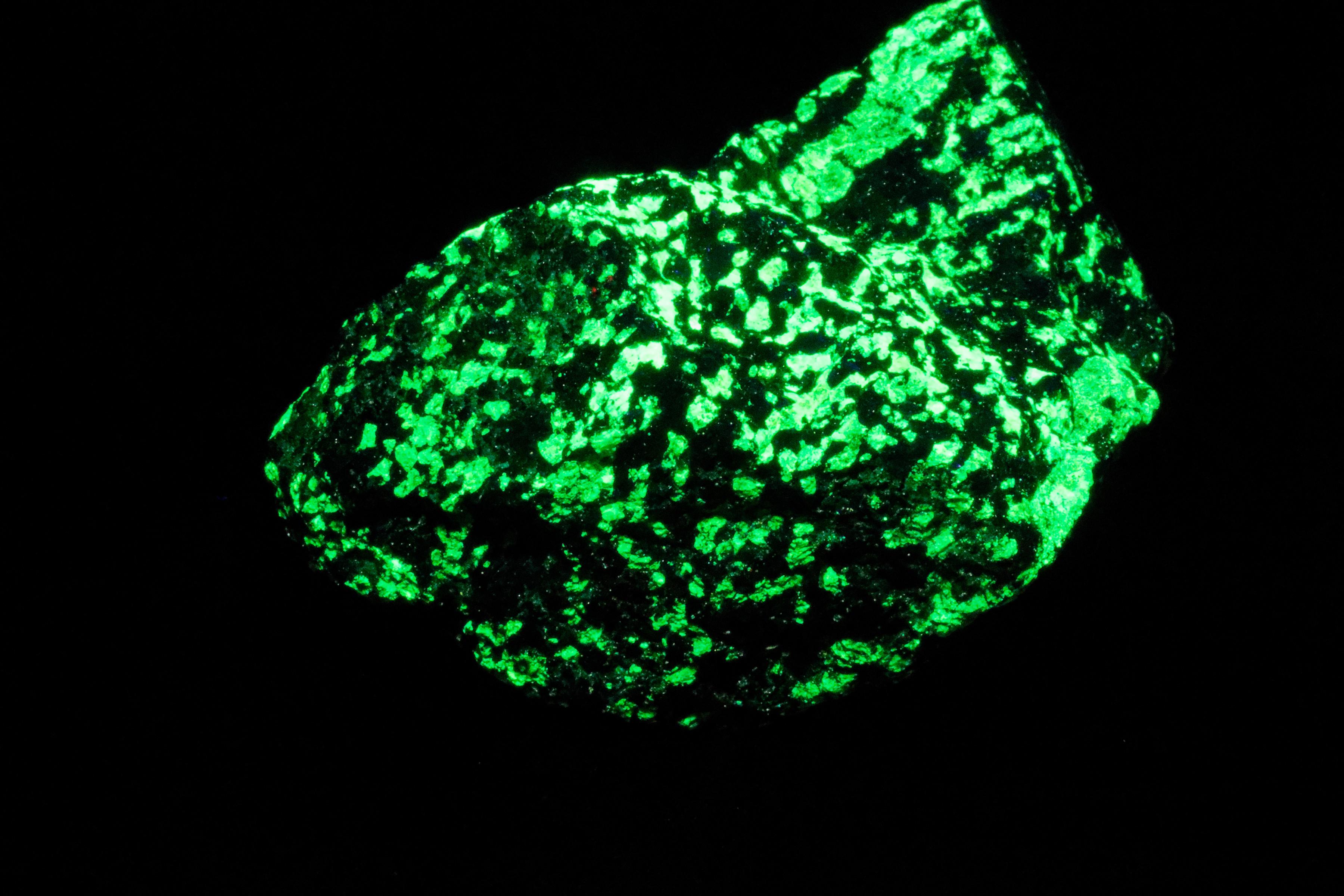
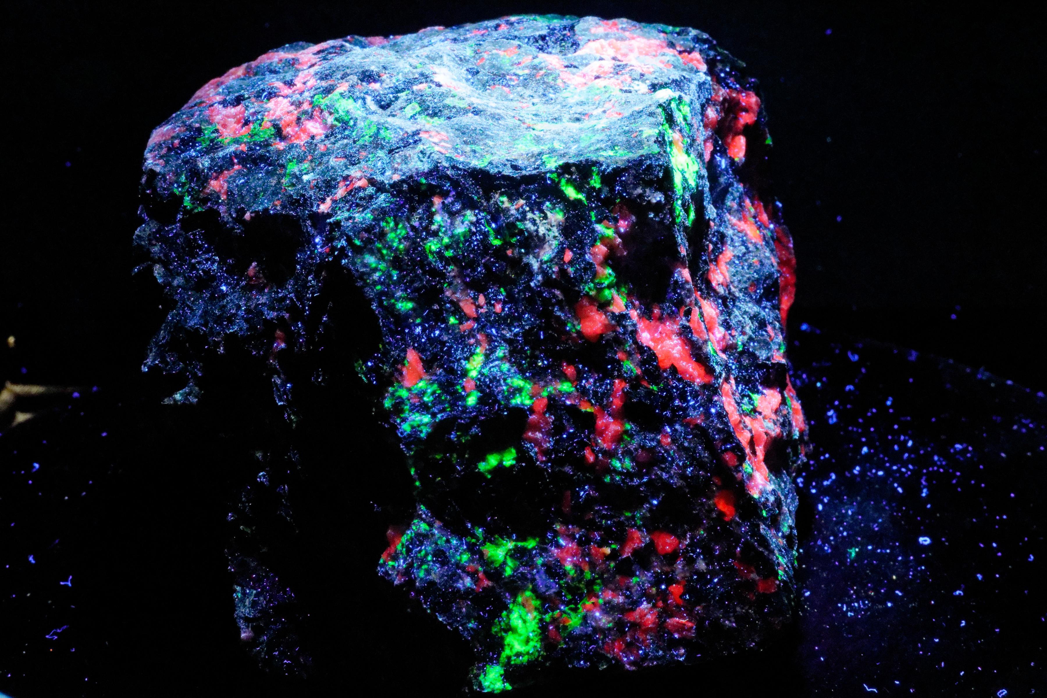
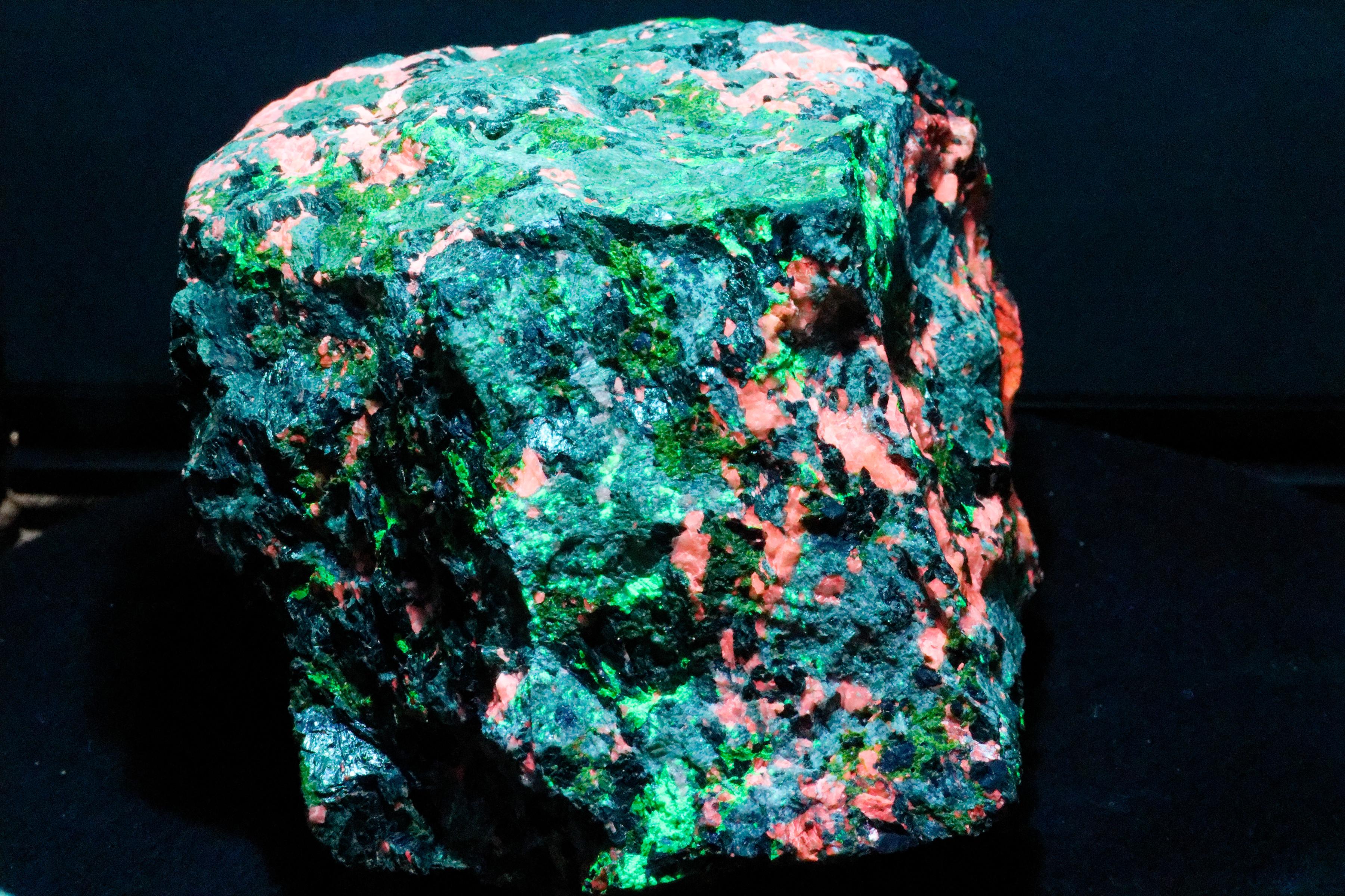
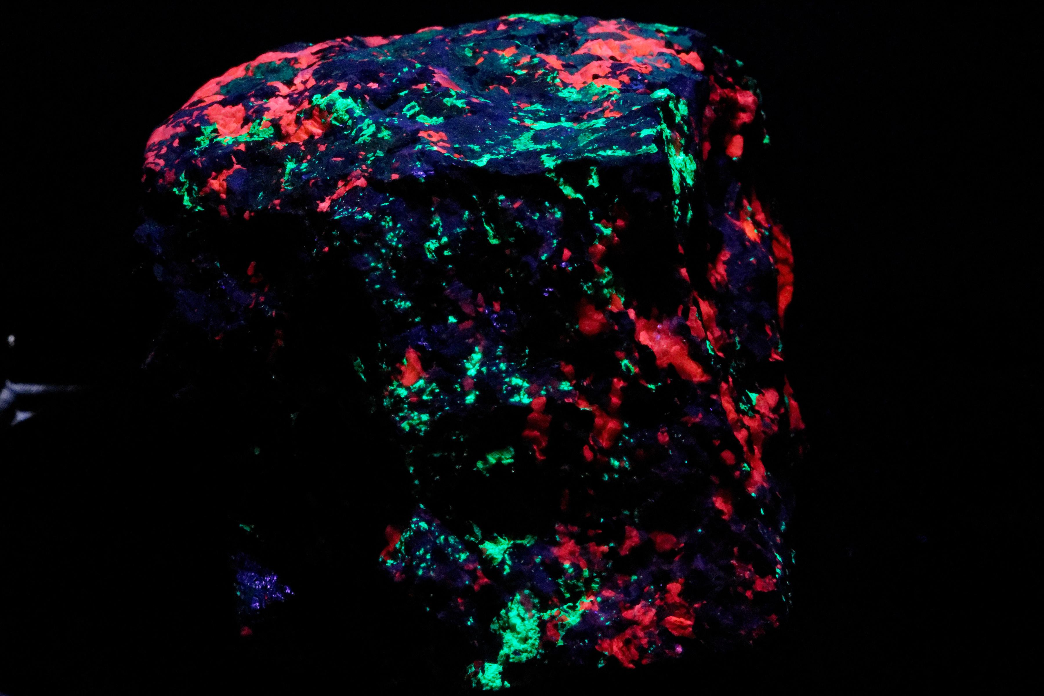
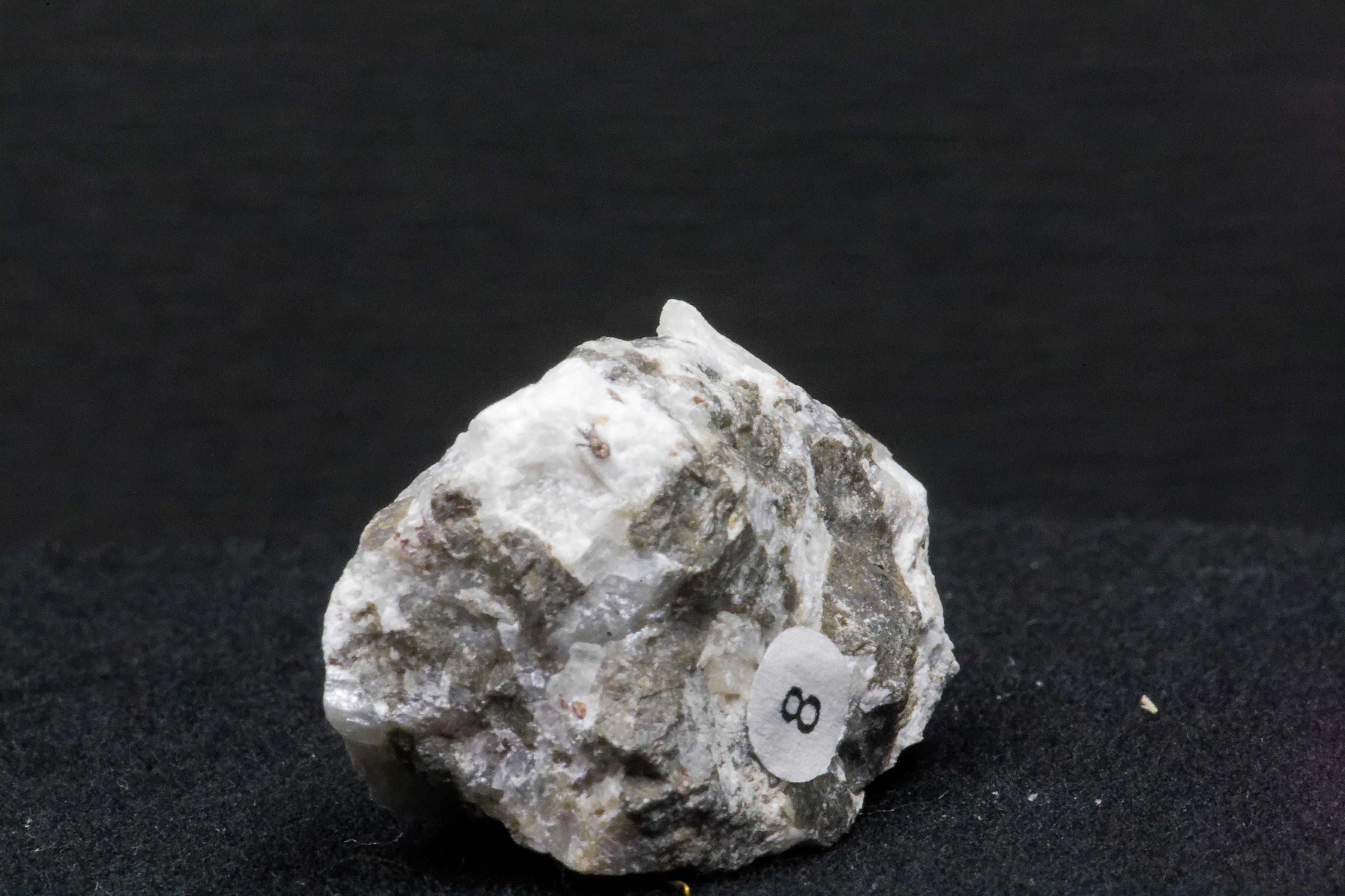
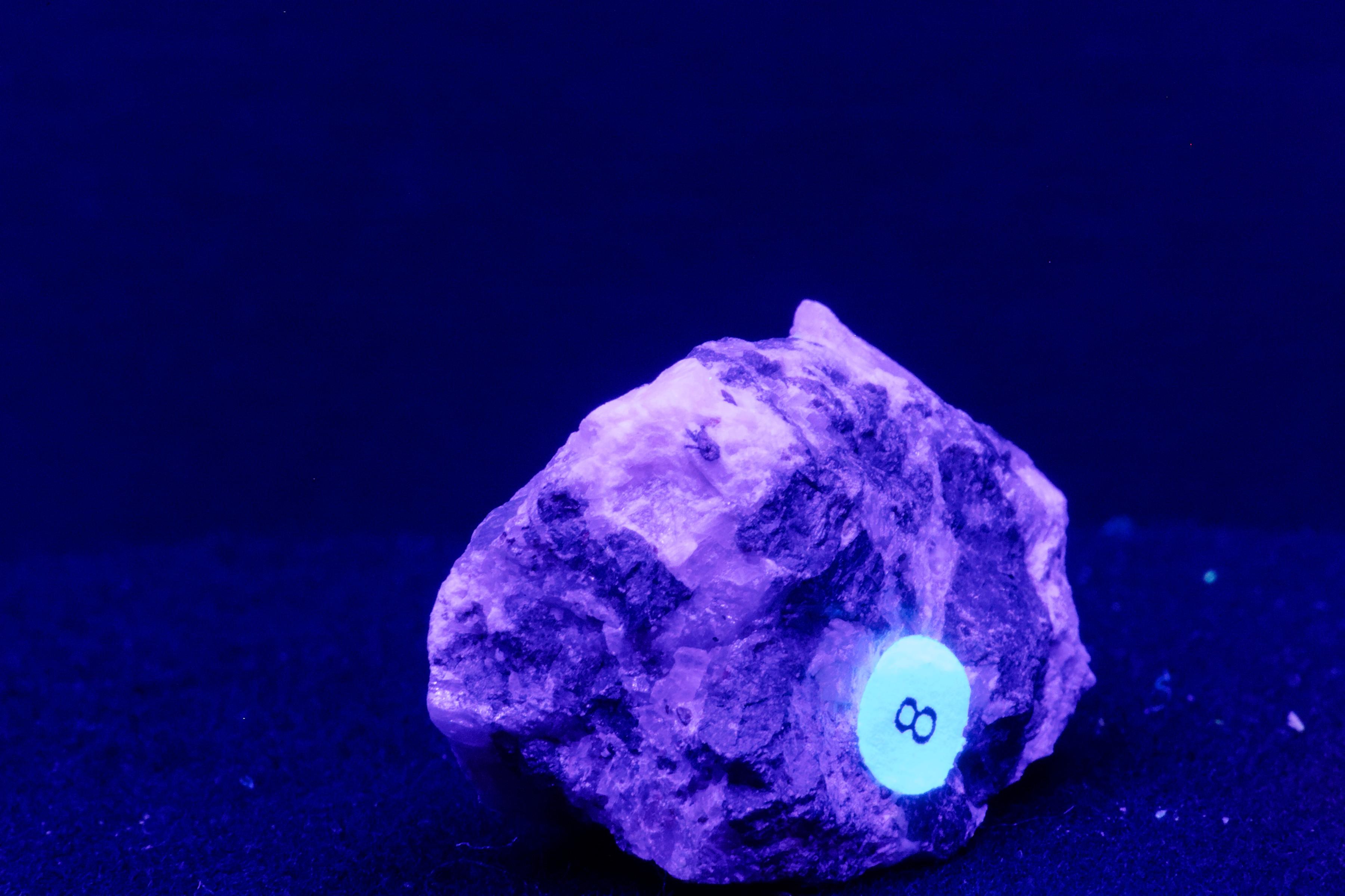
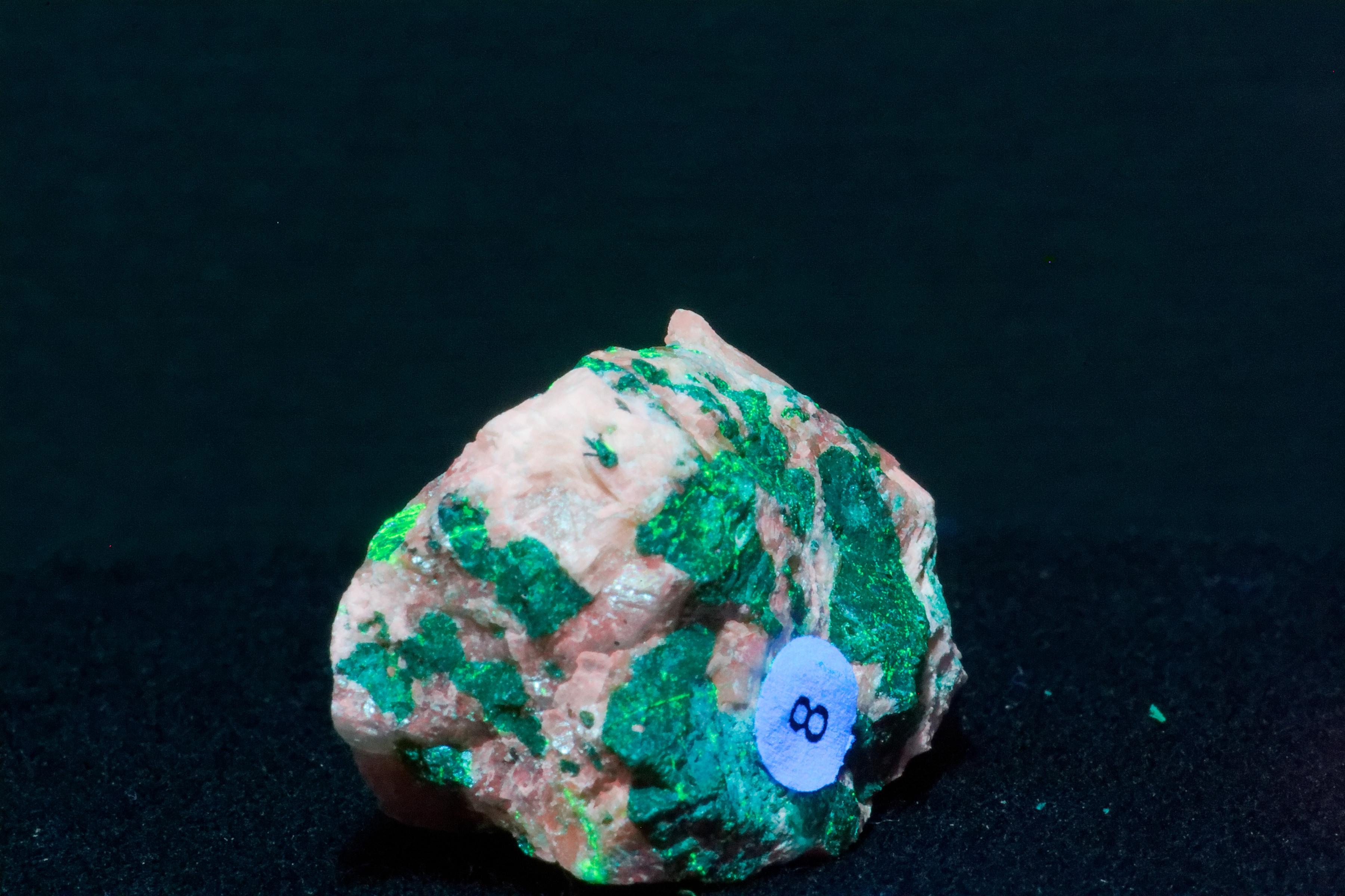
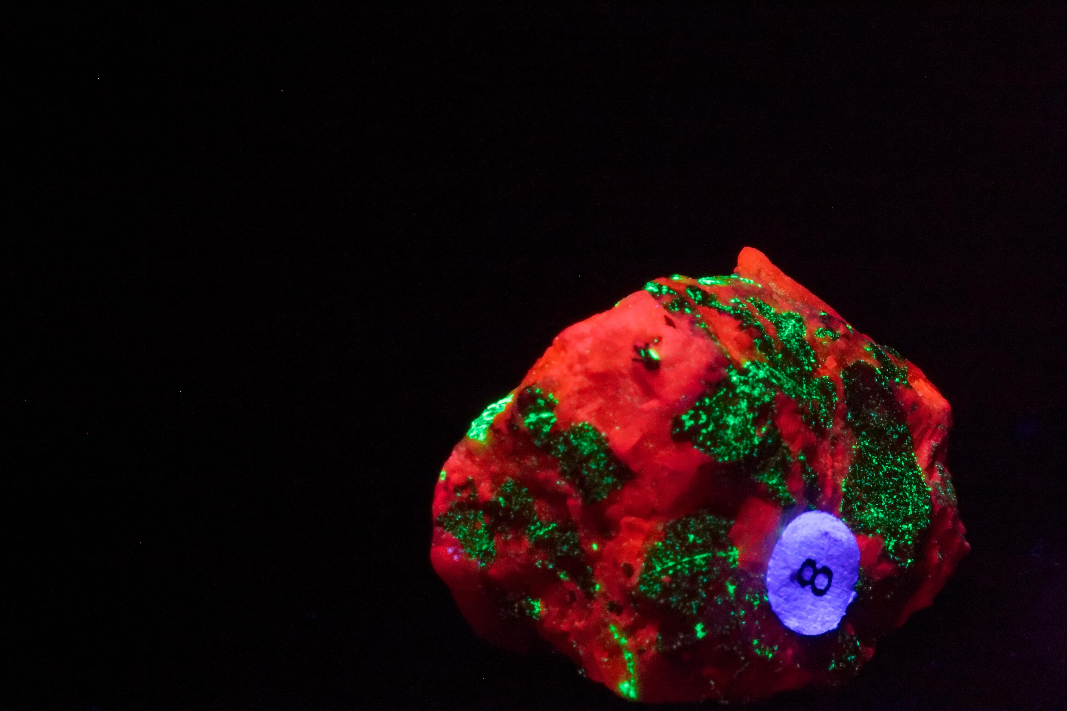
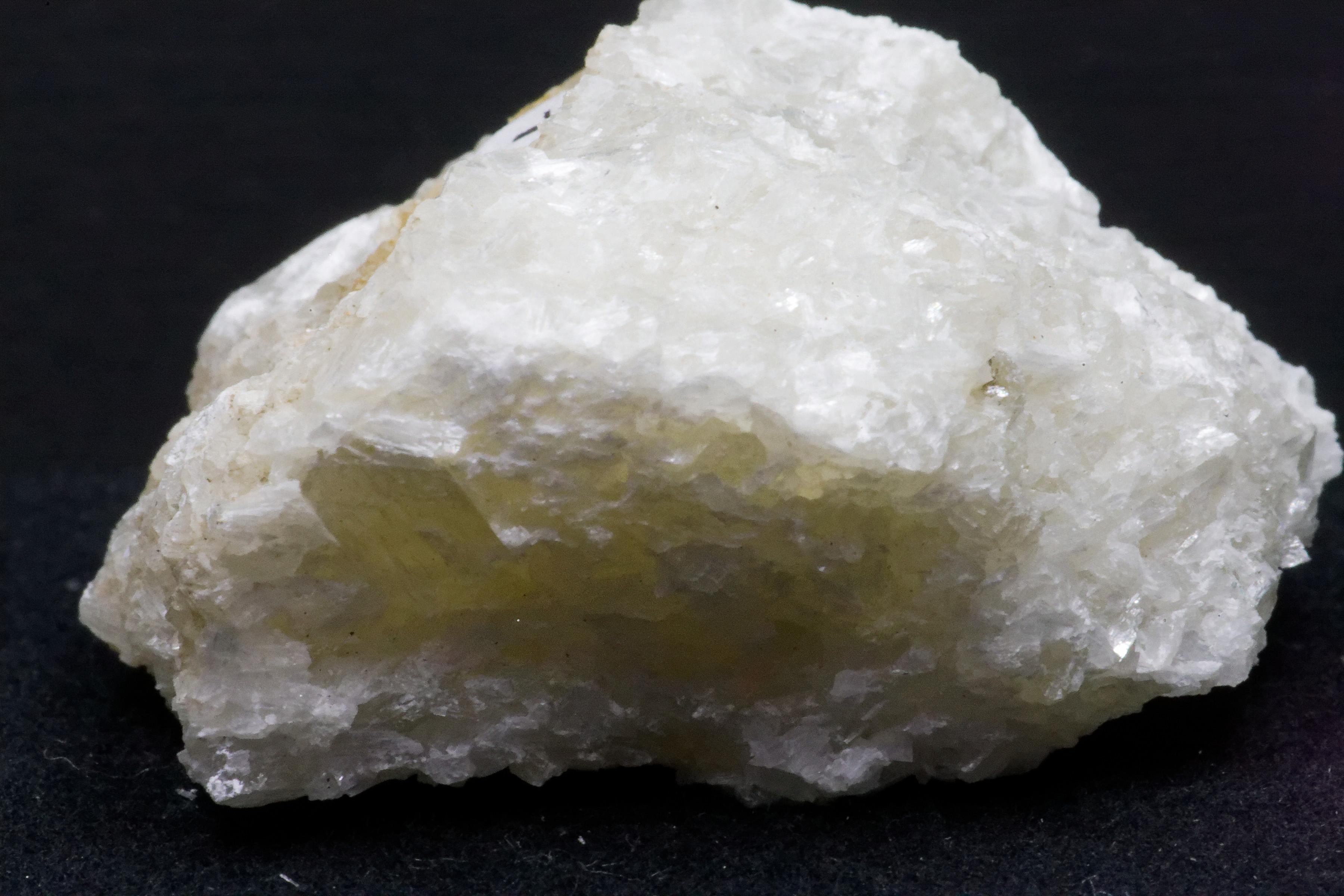
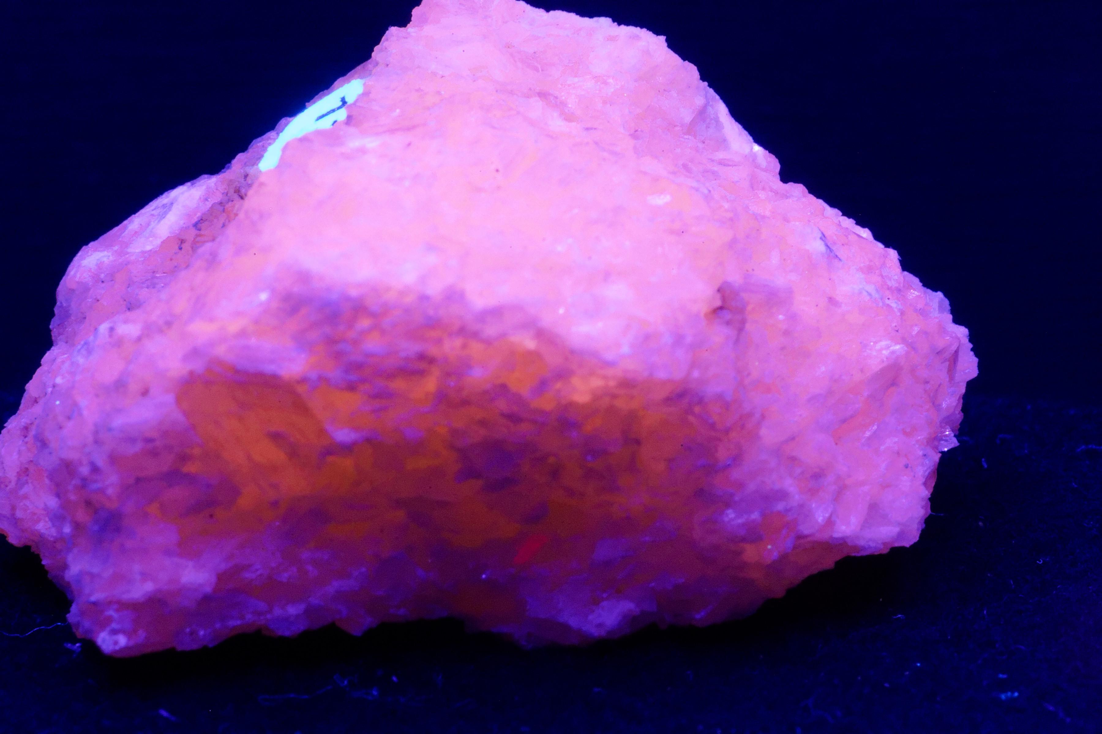
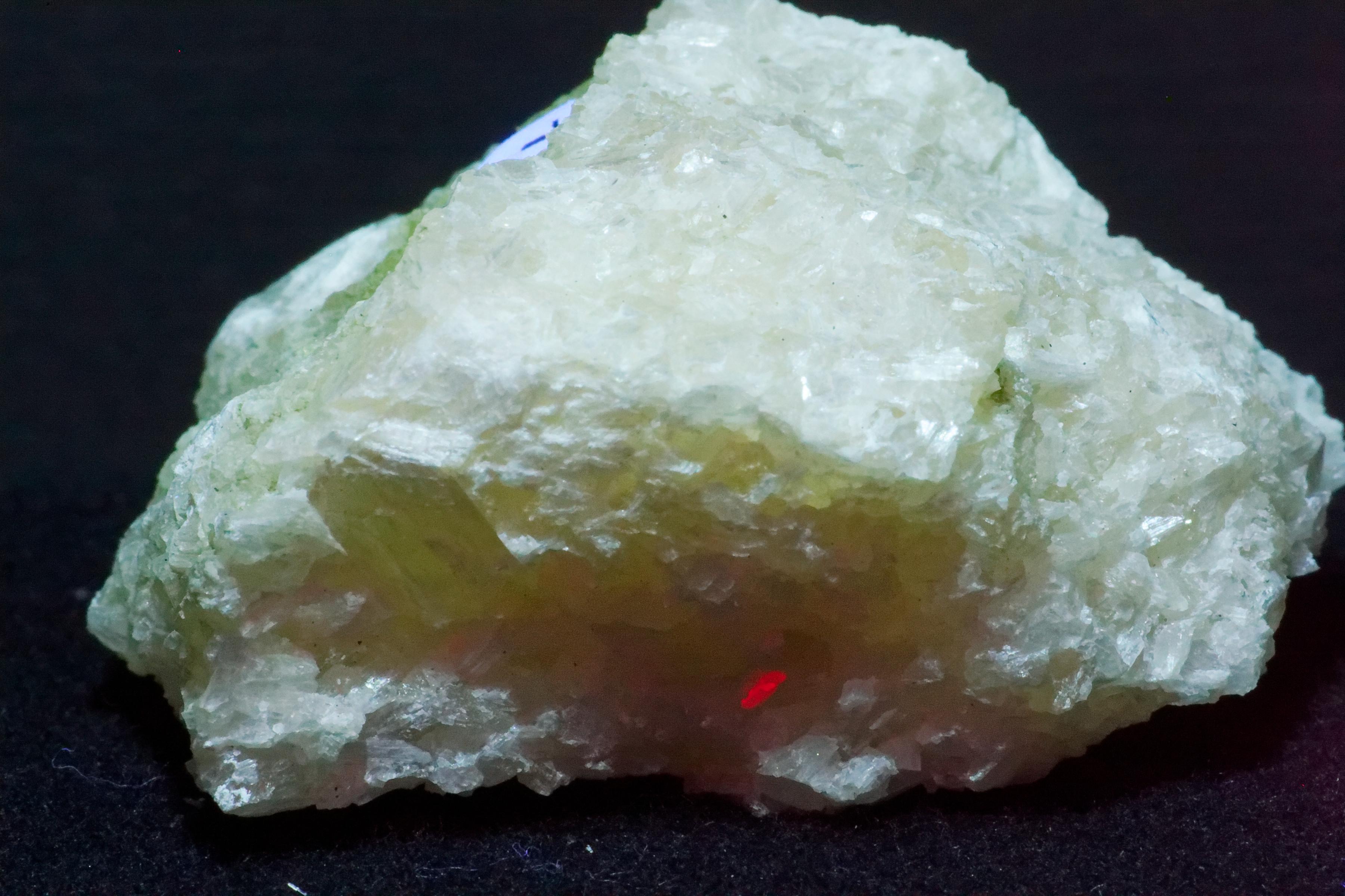
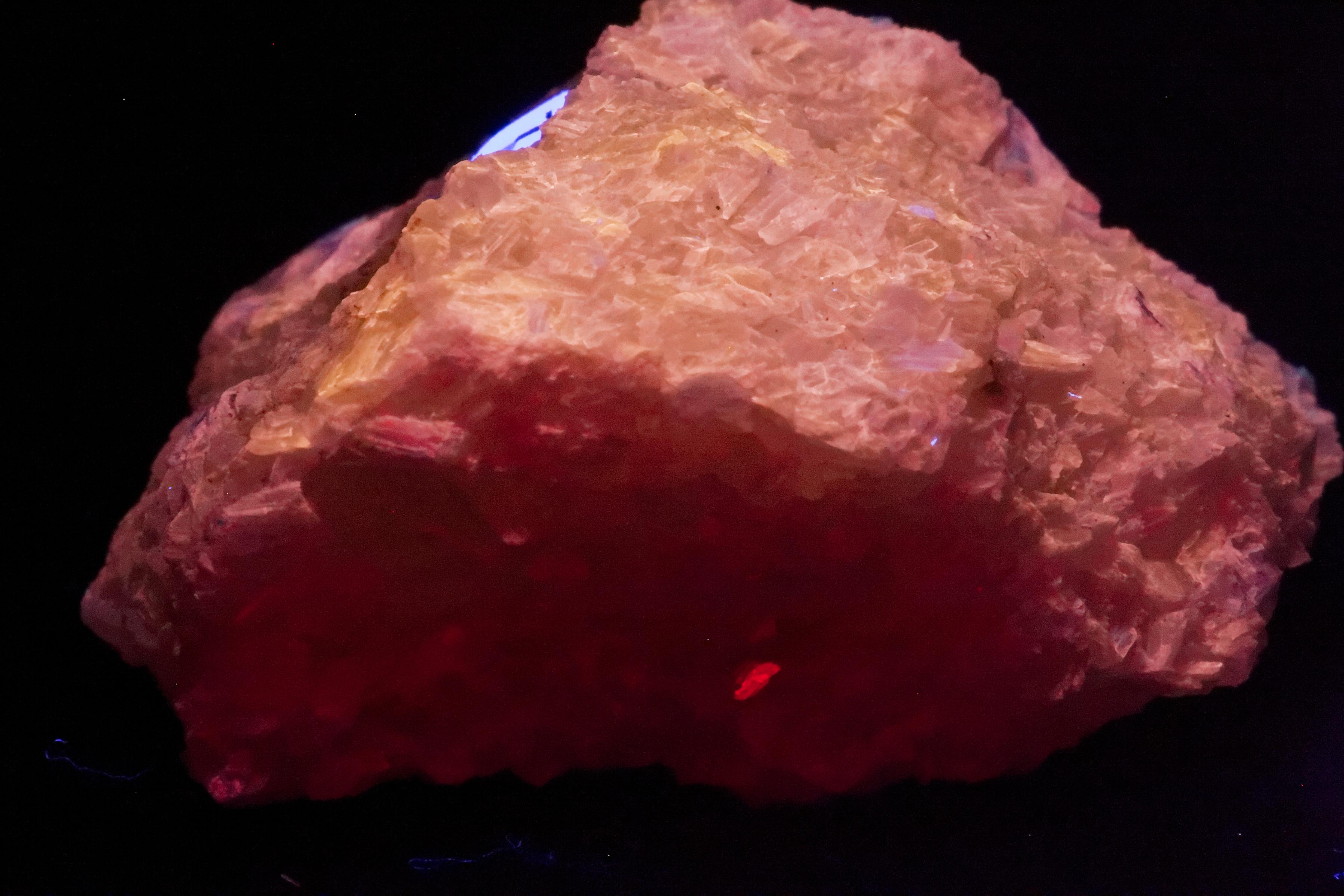
This is a demonstration of color correction using a UV source. The first ten images are matched pairs. The first image is uncorrected. In the second image, color correction is applied. Because light originates from within the surface of the minerals, you cannot correct for an external light source using a standard method such as a color or grayscale card. Some of the light sources "spill" over into the visible spectrum to make matters more complicated. This can introduce a color cast to the whole image. We will consider the entire matter of camera sensor sensitivity to the color spectrum beyond the scope of discussion here. Ultimately, it will be up to the user to decide how accurate the colors represented by their images are.
The last three sets of images demonstrate adjusting the levels of black down, and no white balance corrections applied. This visual representation is closer to what you might see with direct observation. We use it as a part of our recipe for processing images.
We would like to hear what other users come up with.
What Needs to Explored Next
Many low-frequency UV LEDs are on the market, and more are being added each month. They are in extremely short supply and, for the most part, costly. (As of February 2023.) There are issues with luminance, thermal properties, and power, That put them out of the range of beginning hobbyists. This will likely change in the near future. Their advantage is that they can be clustered in a smaller area so that you can get away with a smaller bandpass filter. ( With proper thermal regulation, an aluminum-cored PCB, and good heatsinks.) A good bandpass filter is the most expensive part of the system.
There are only a small number of companies that make uv bandpass filters. The good ones are costly and come in sizes and form factors that are not convenient for hobbyists.
So, the list for the future:
- Bandpass filter and their mounts.
- UV LEDs with a narrower frequency range.
- UV LEDs with a finer center frequency.
- A cheap method of comparing UV illuminance.
- UV diffusers.
- Aluminum mirrors for UV
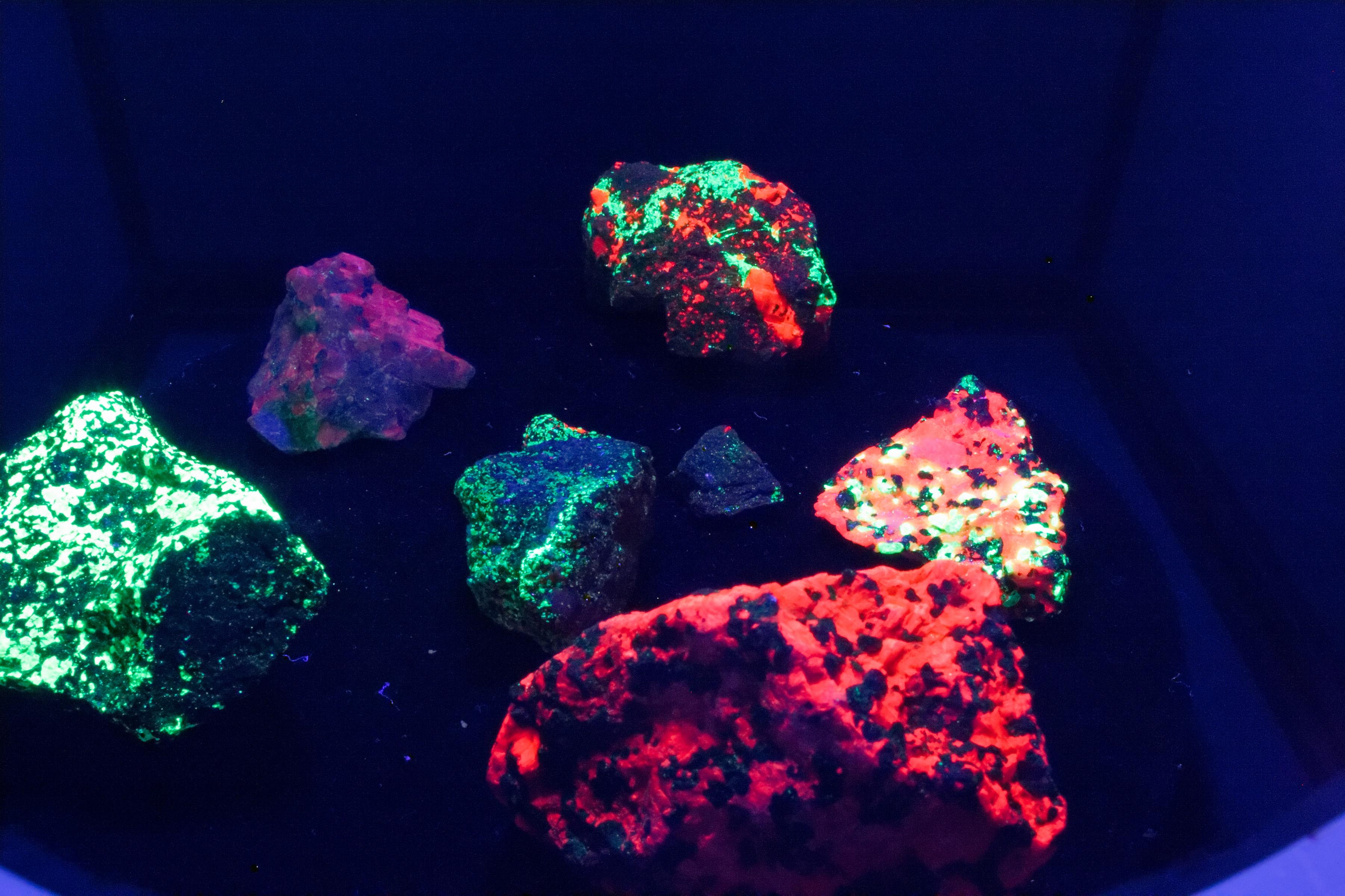
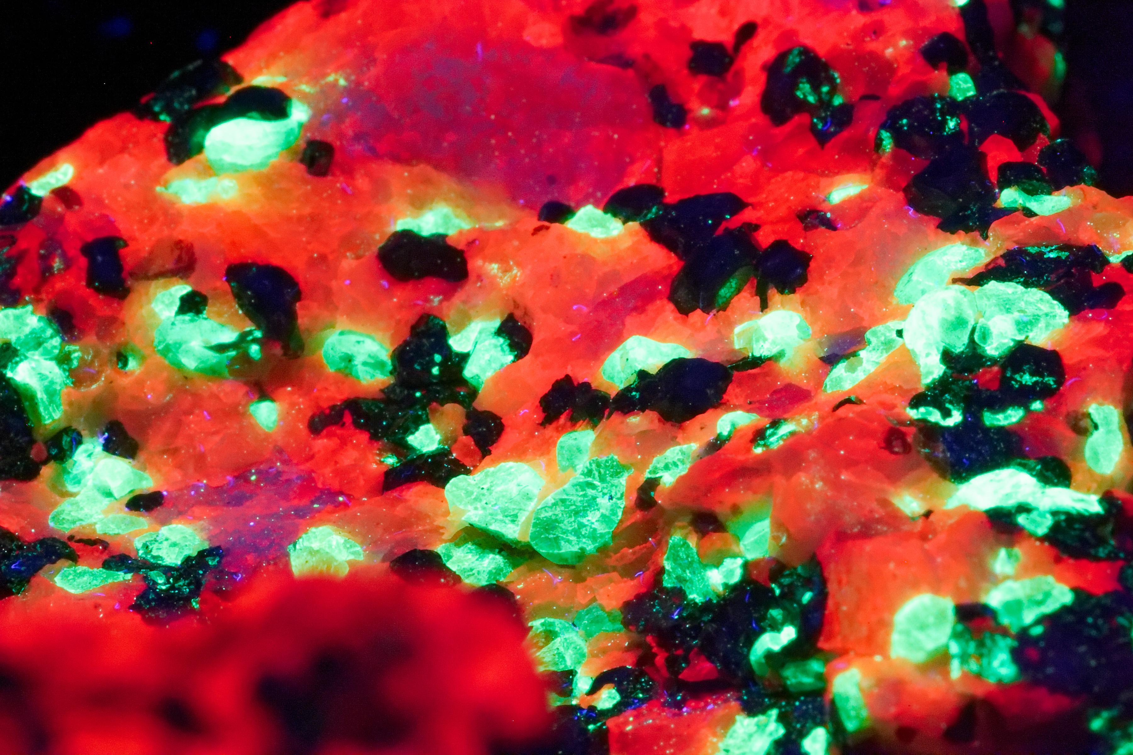
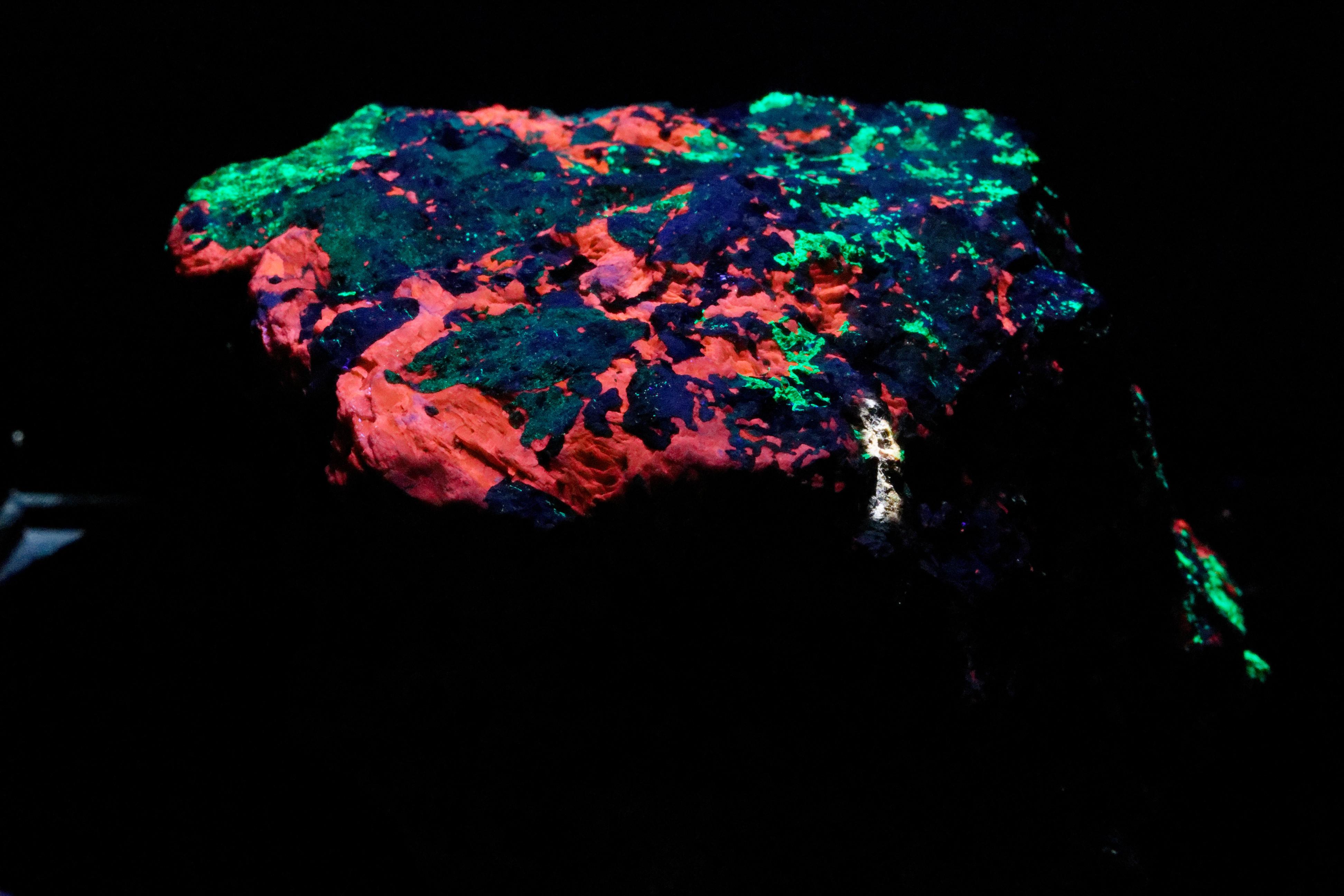
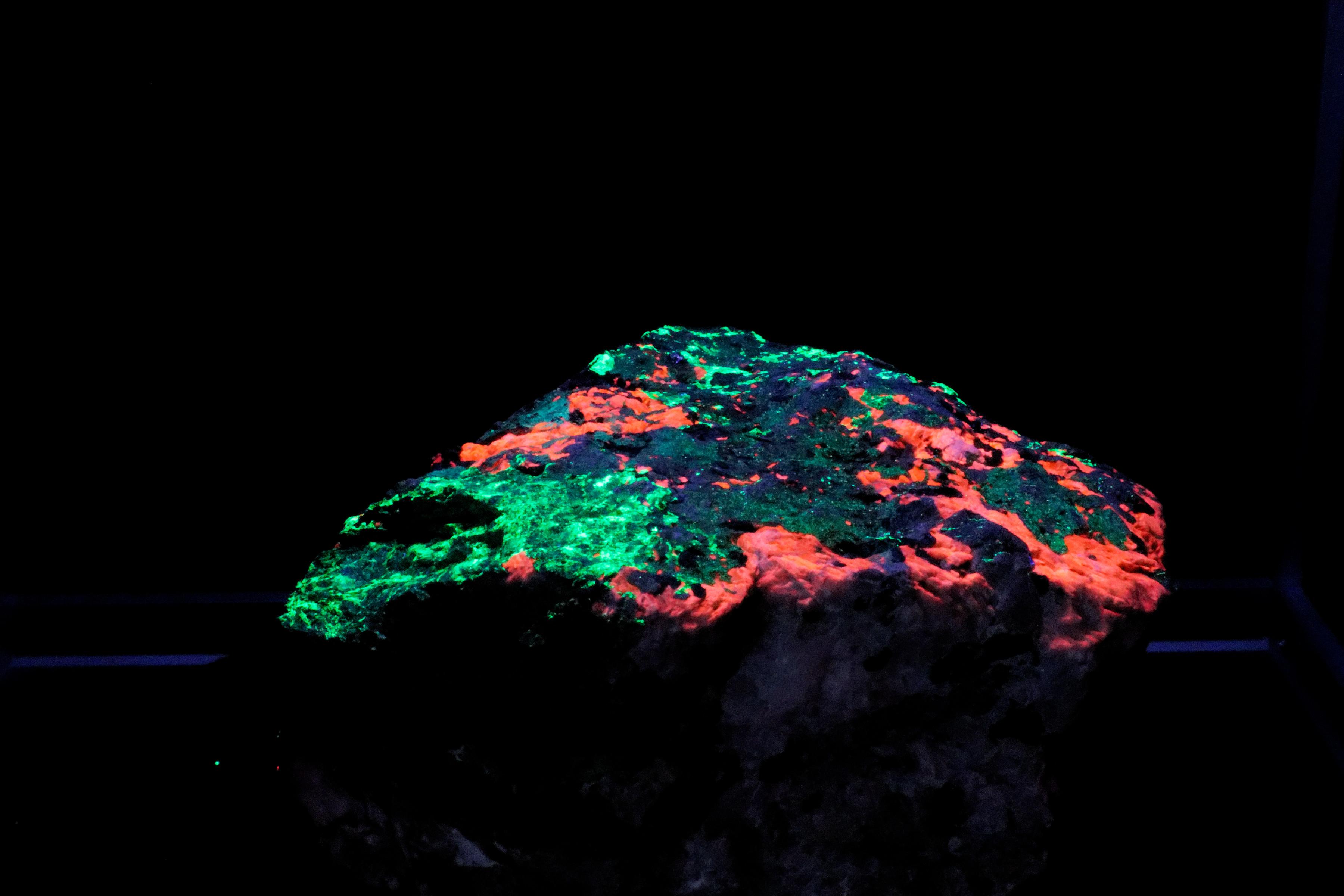
Some Images
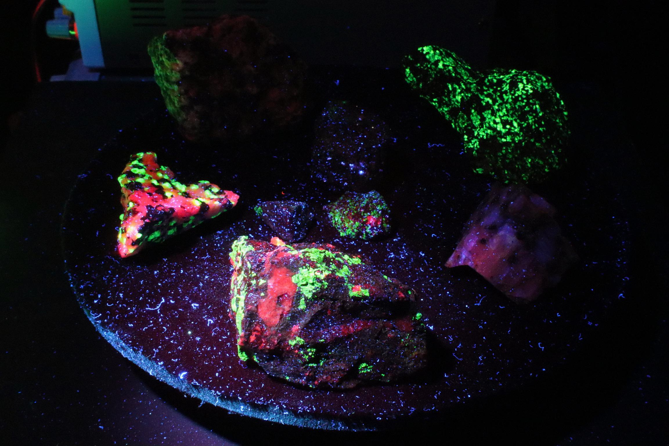
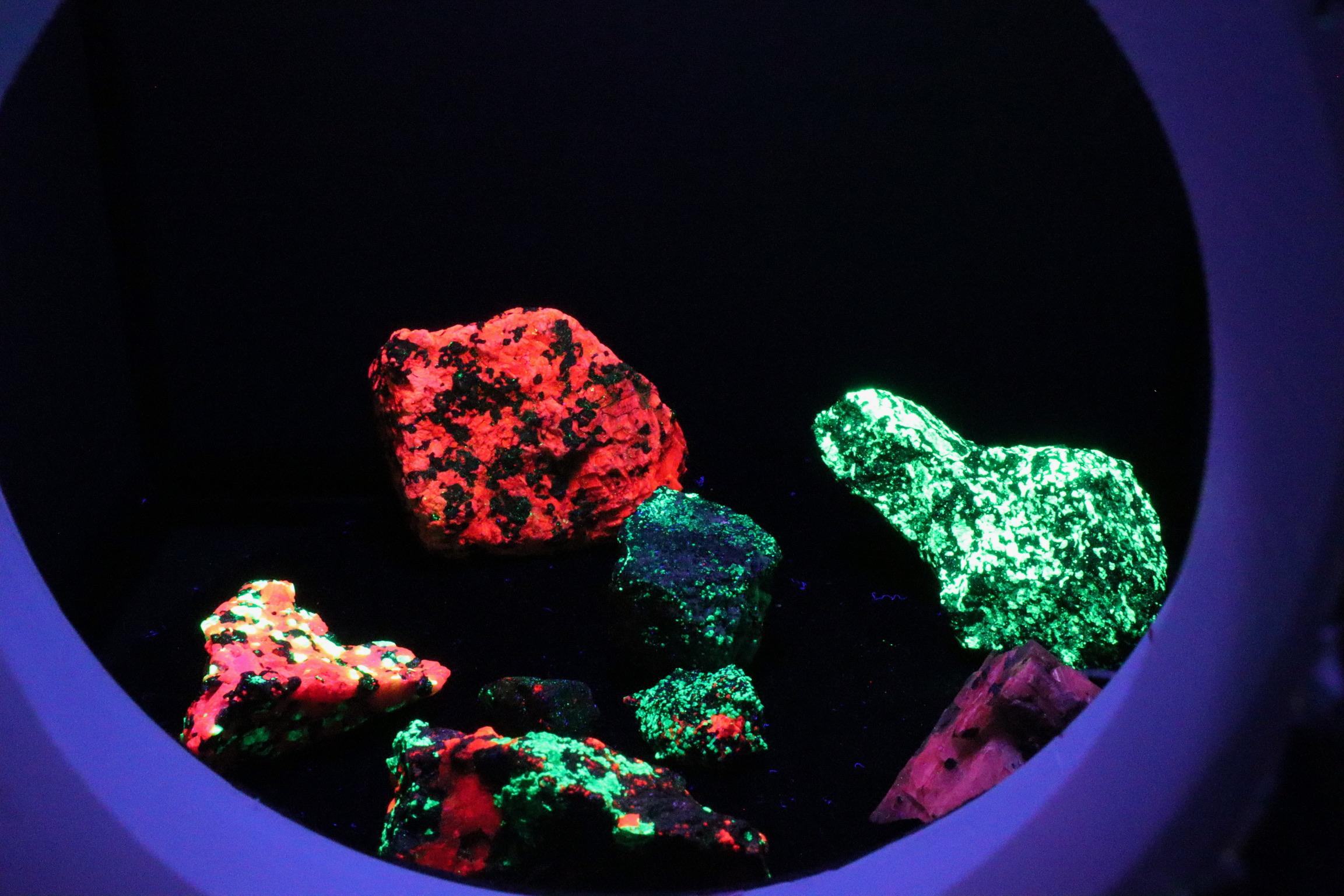
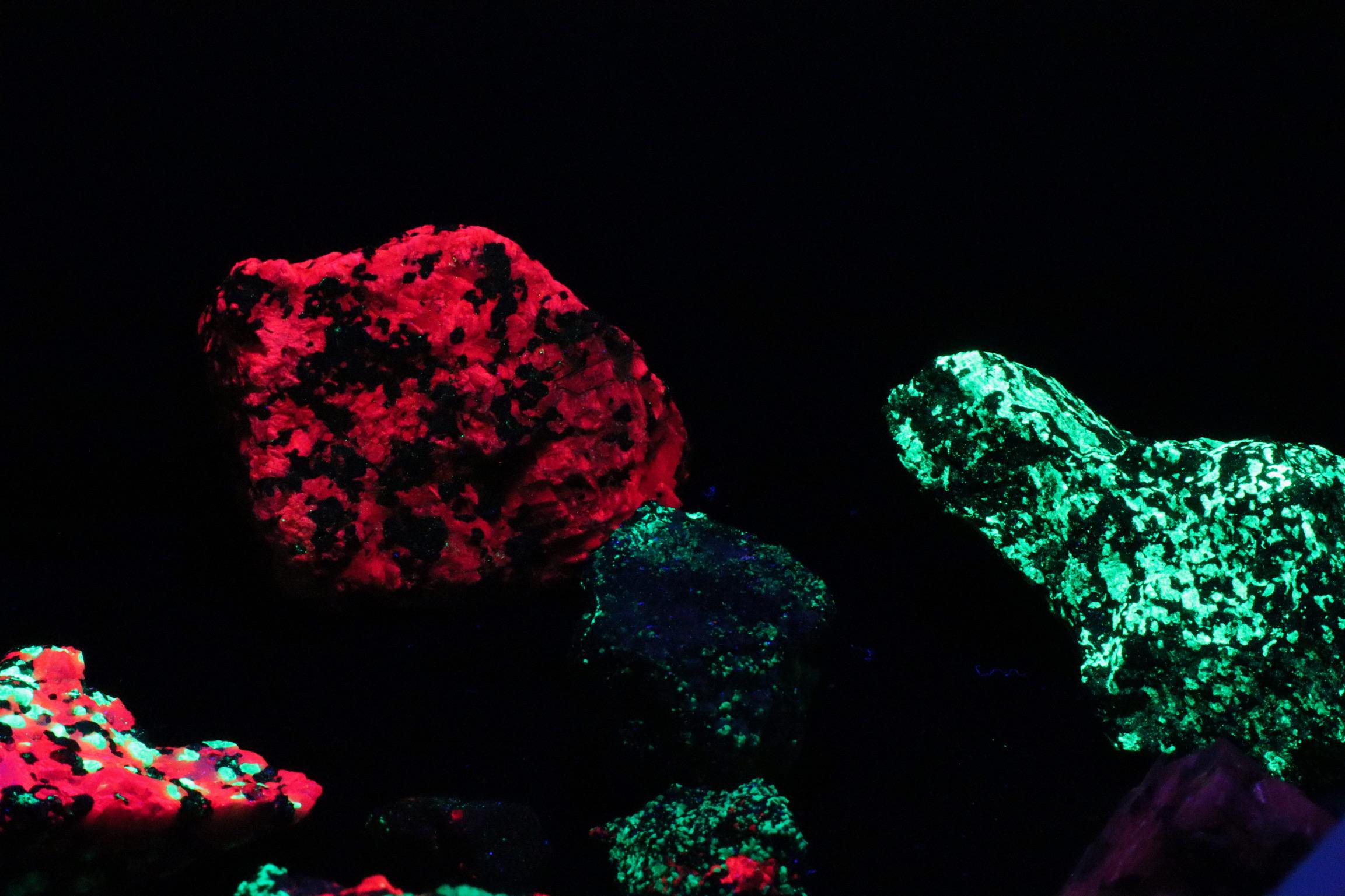
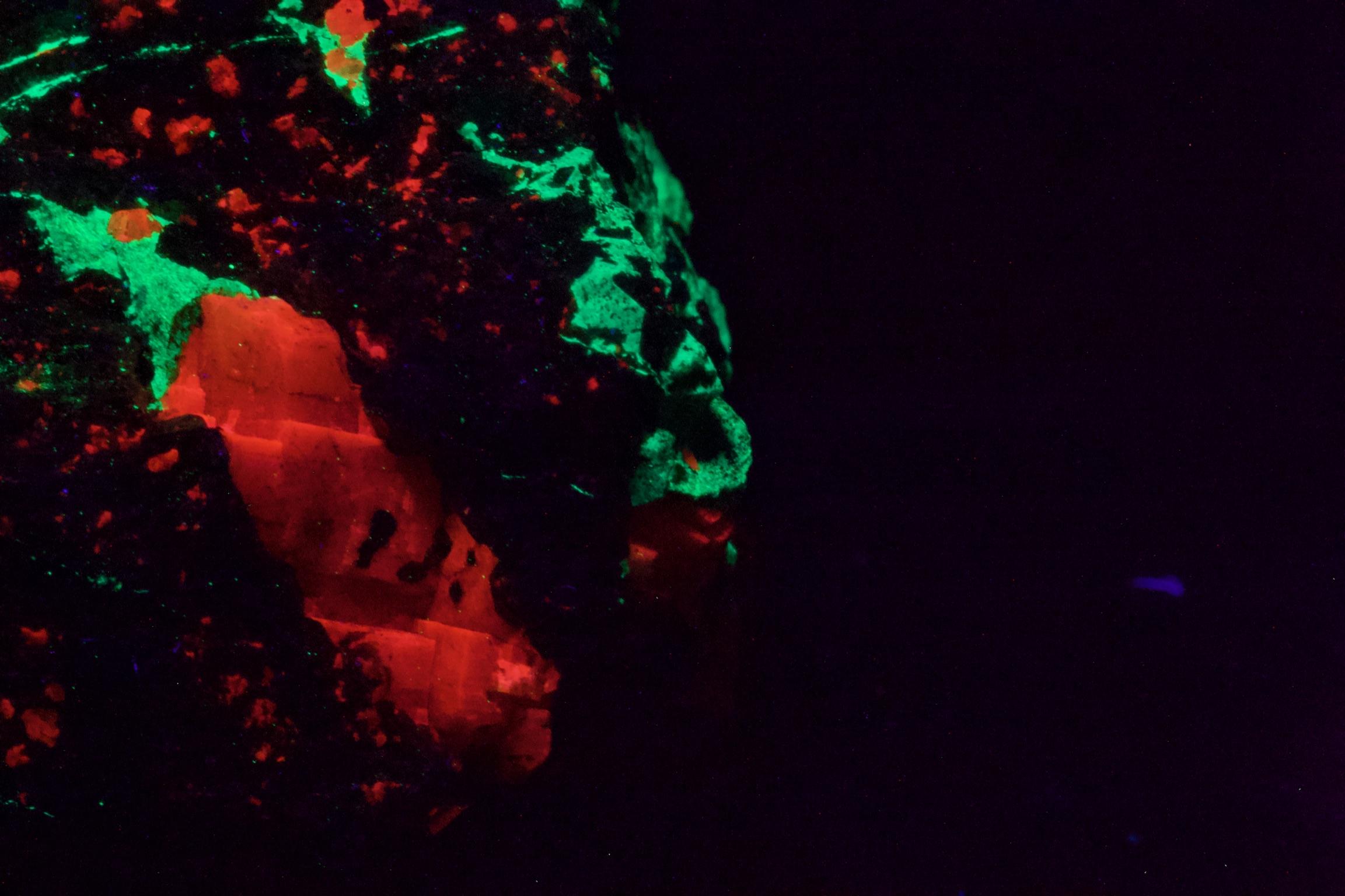
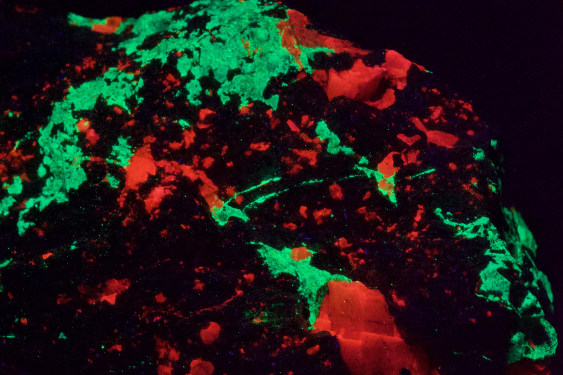
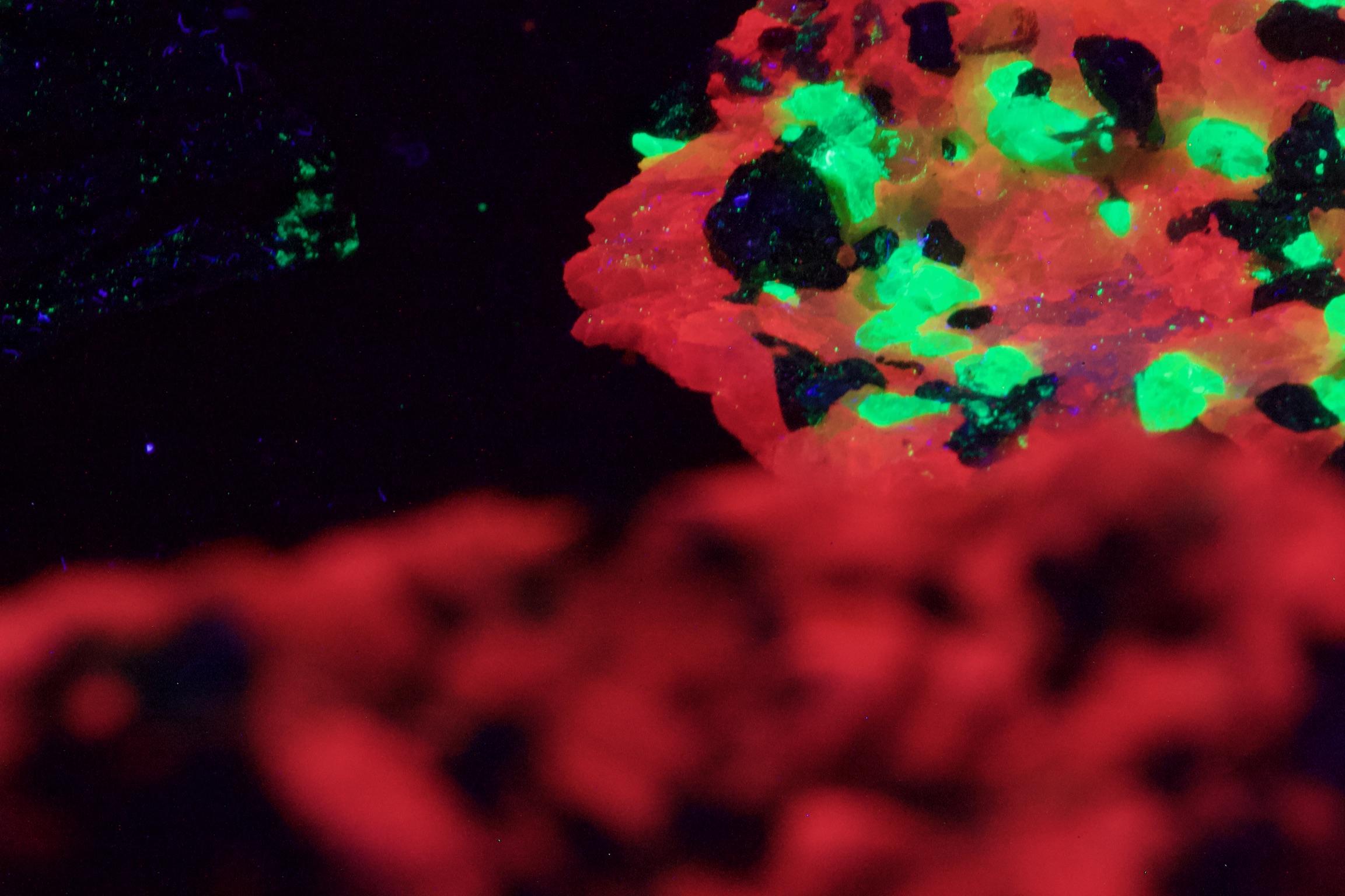
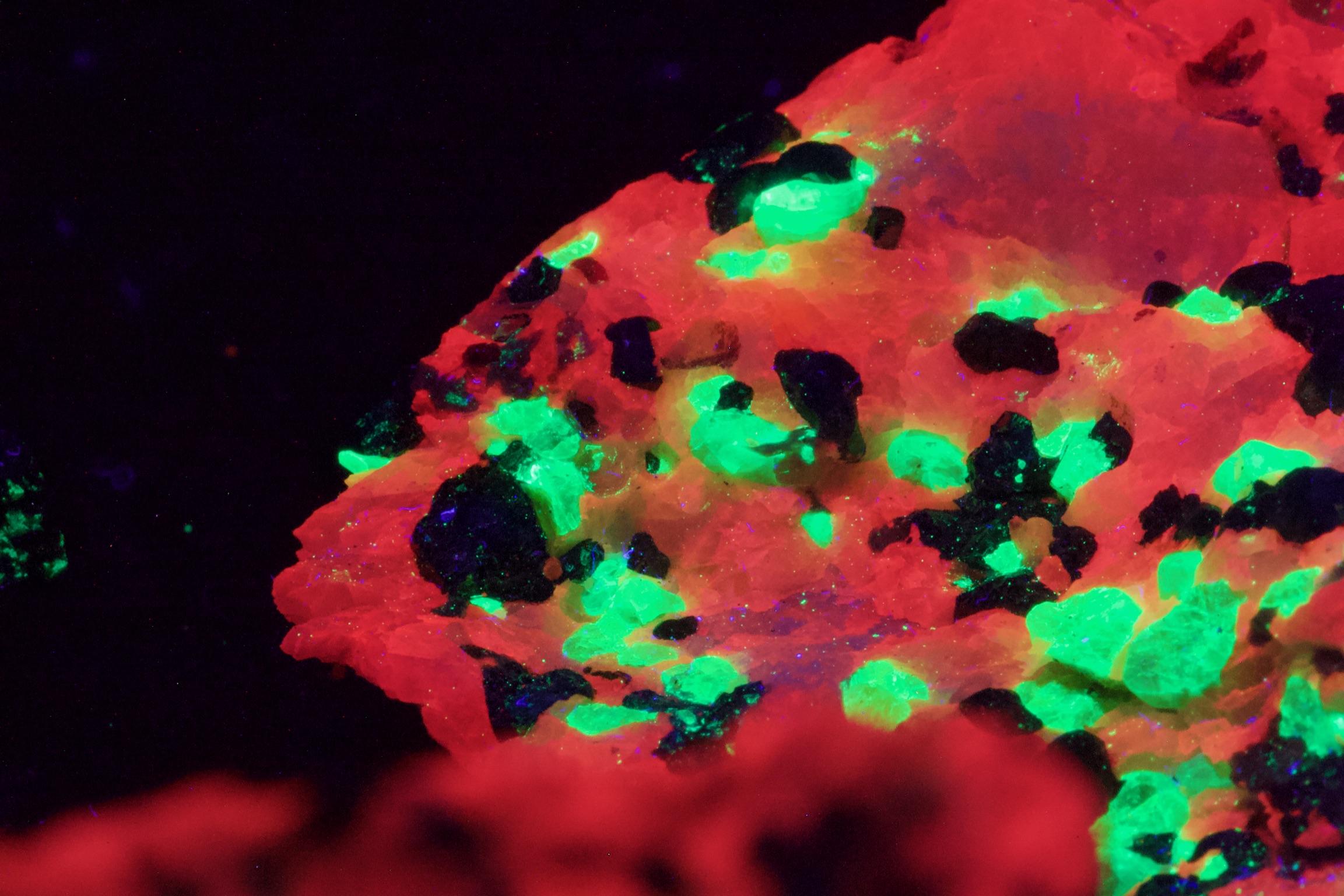
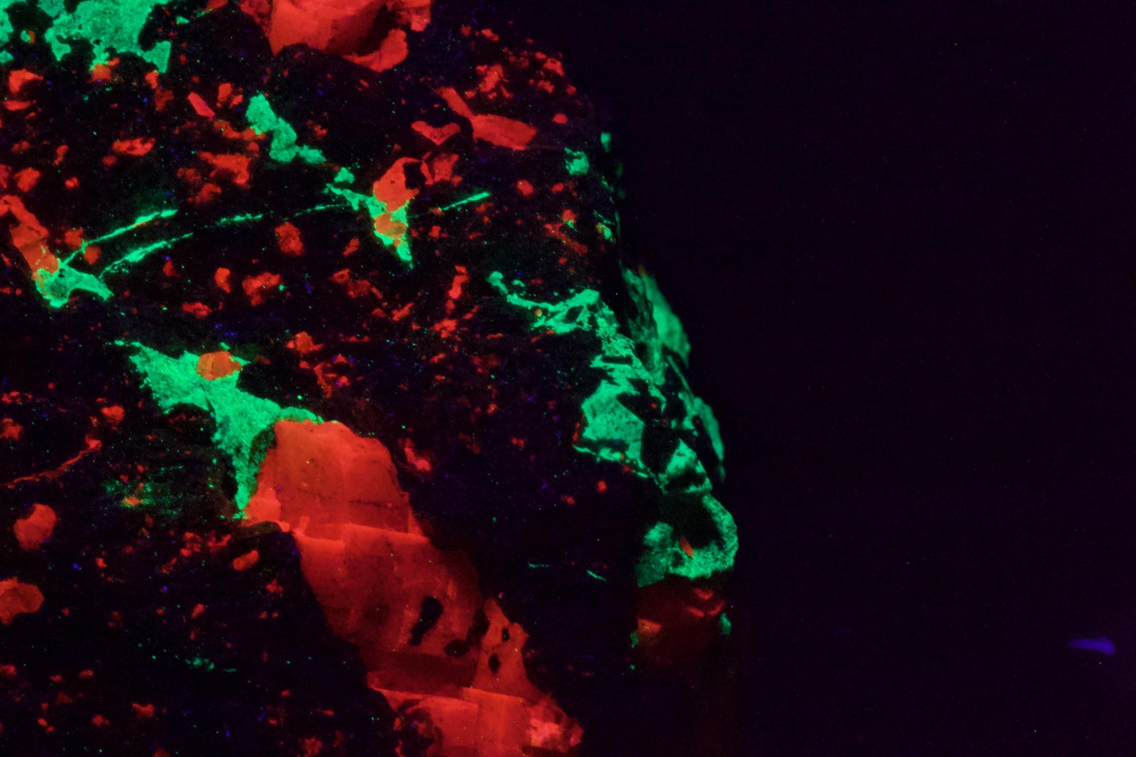
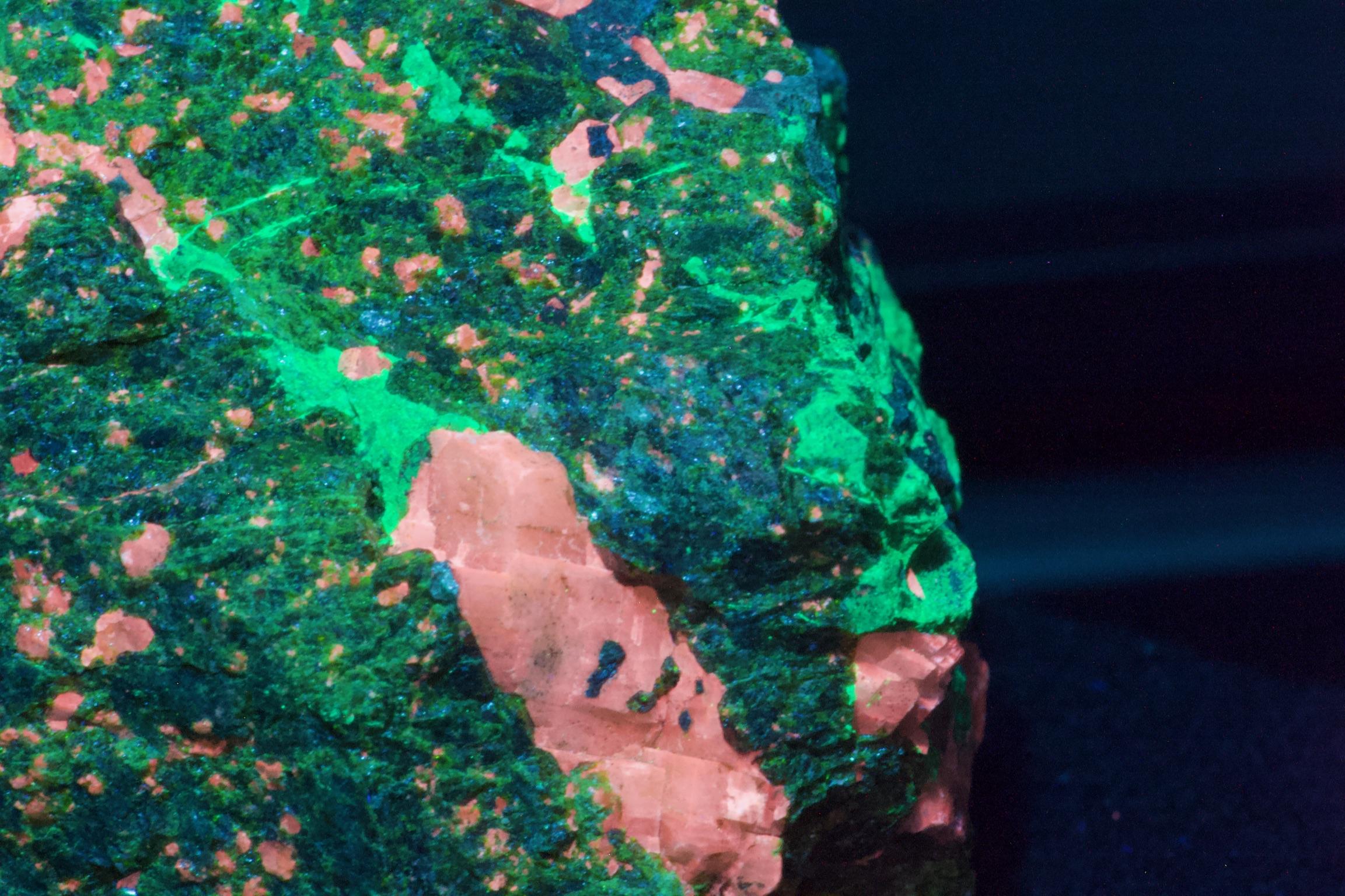
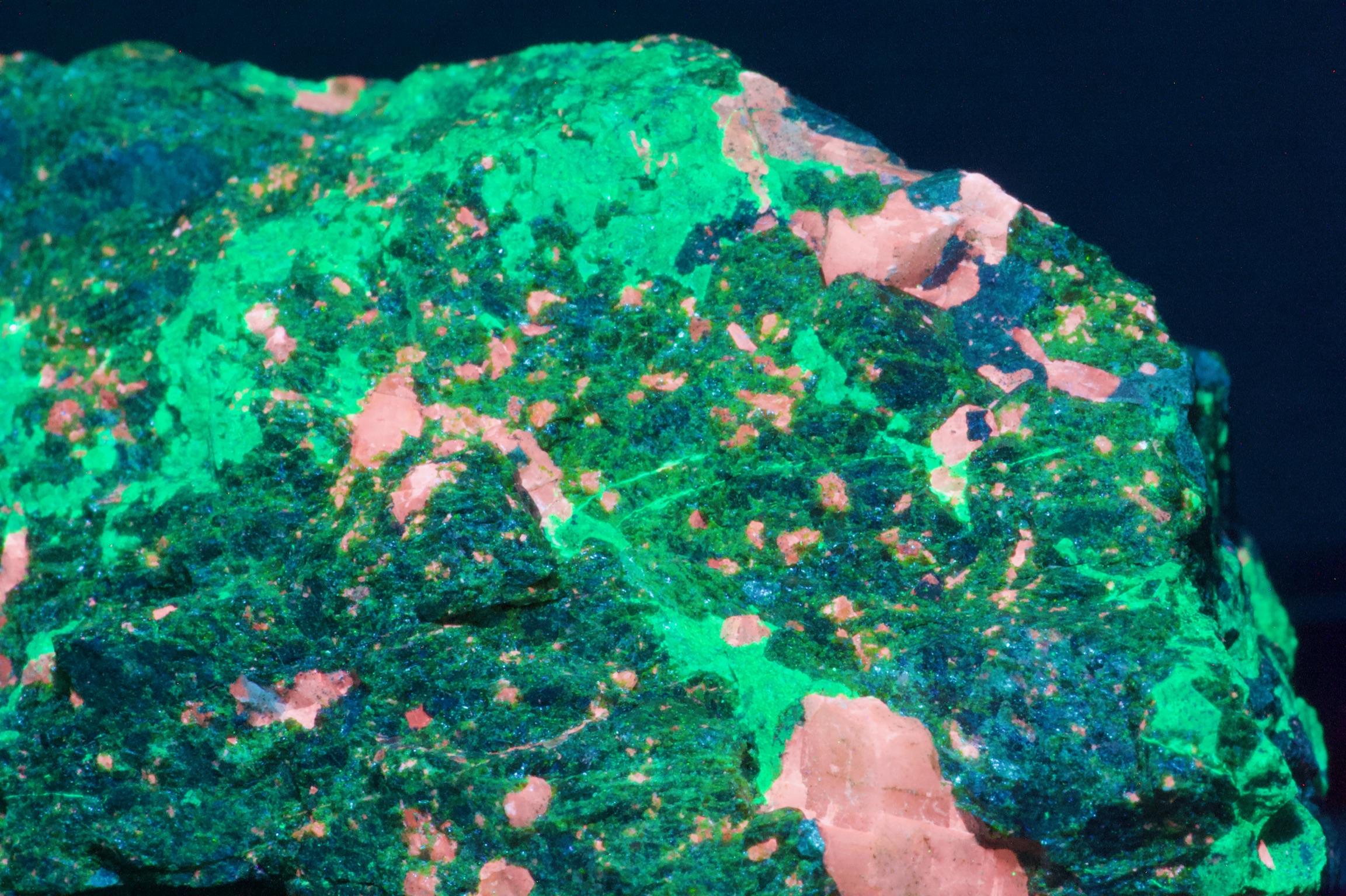
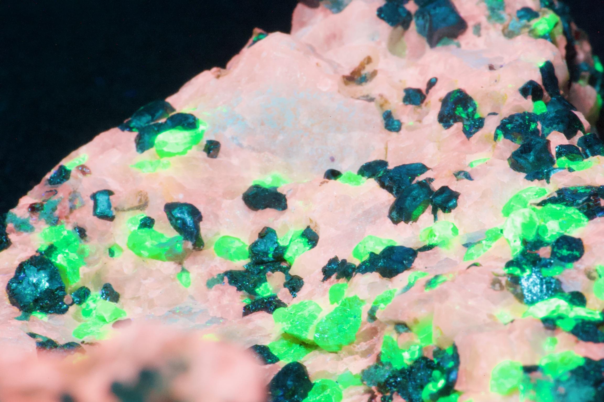
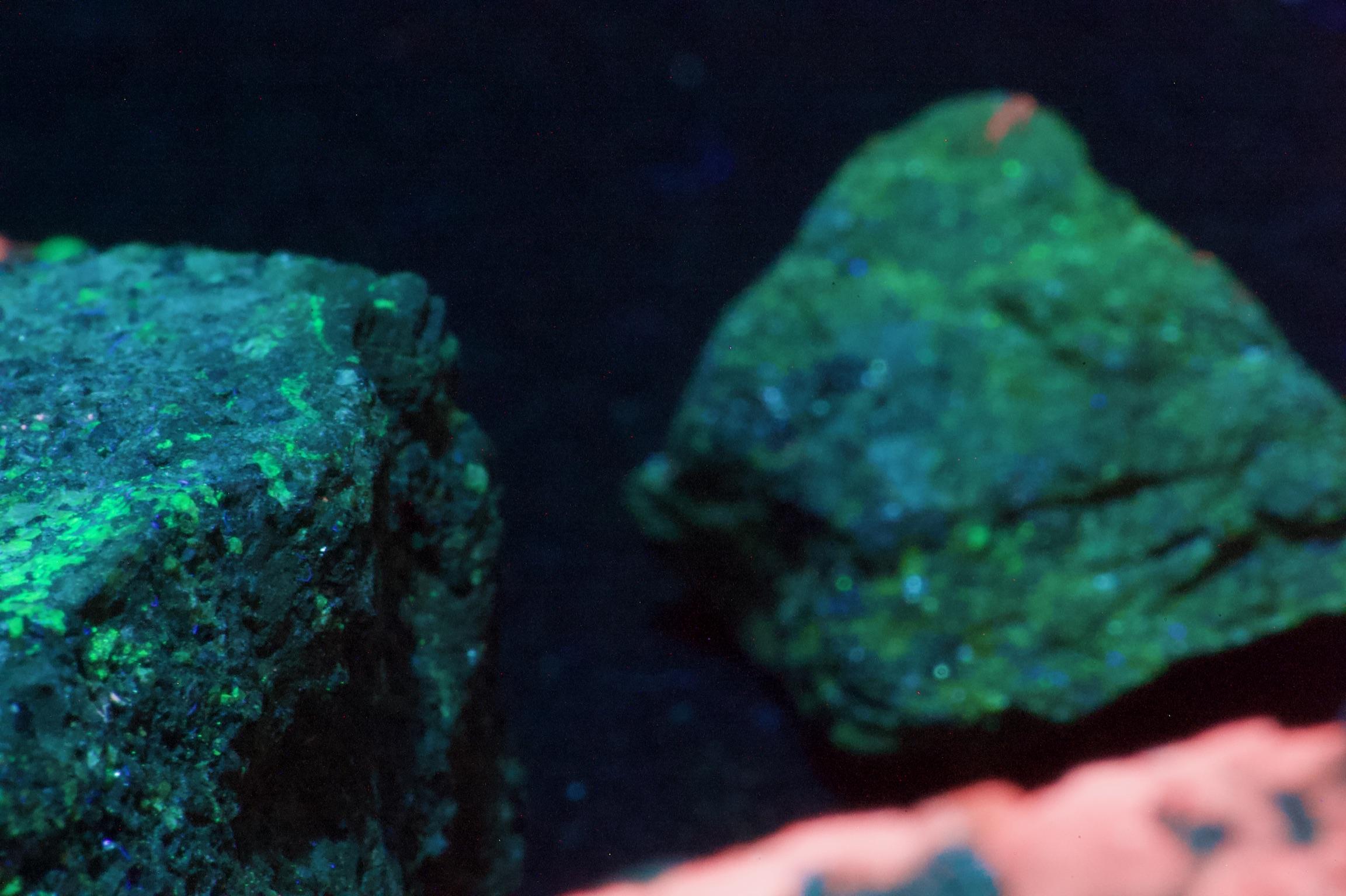
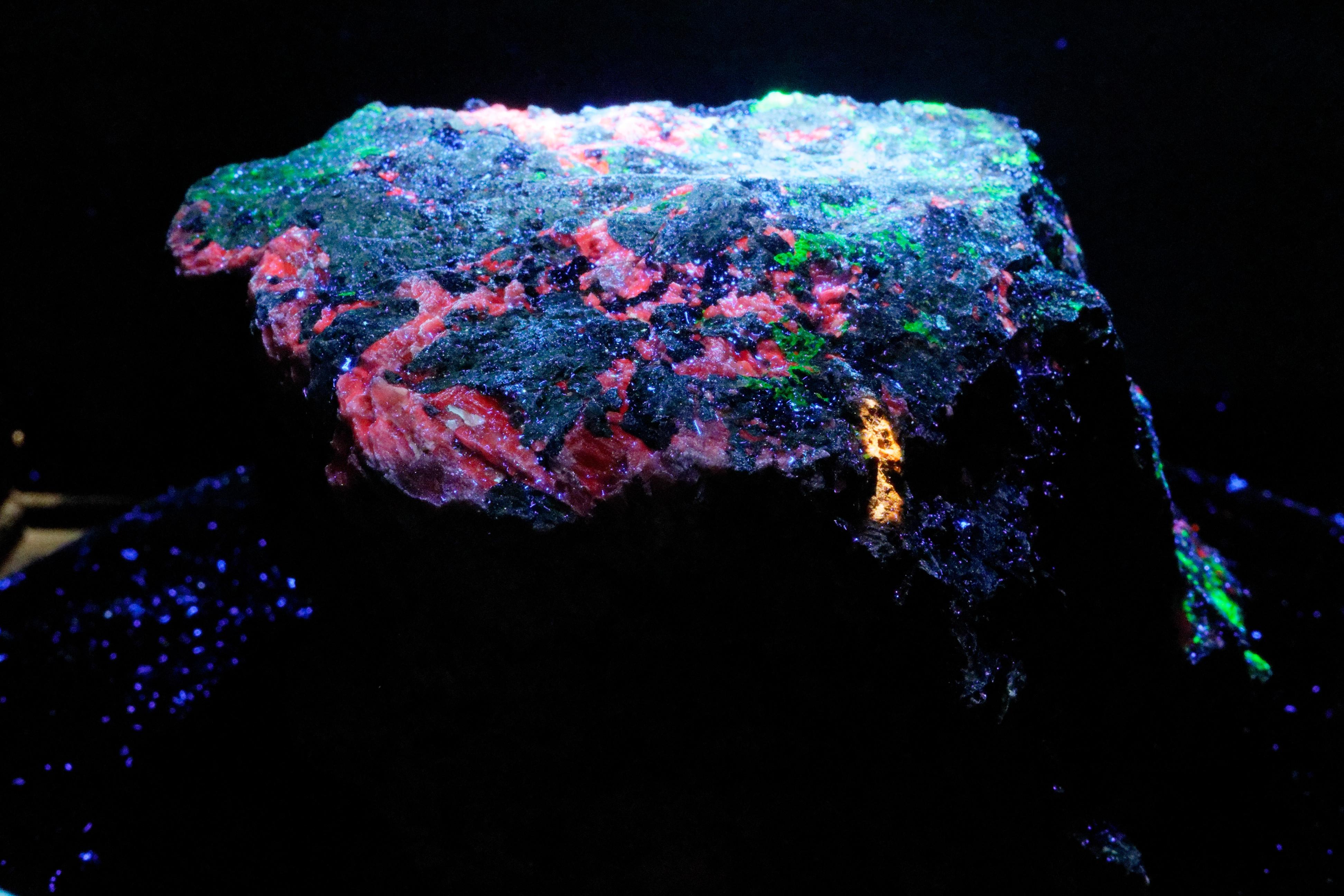
A few of the images we have produced.
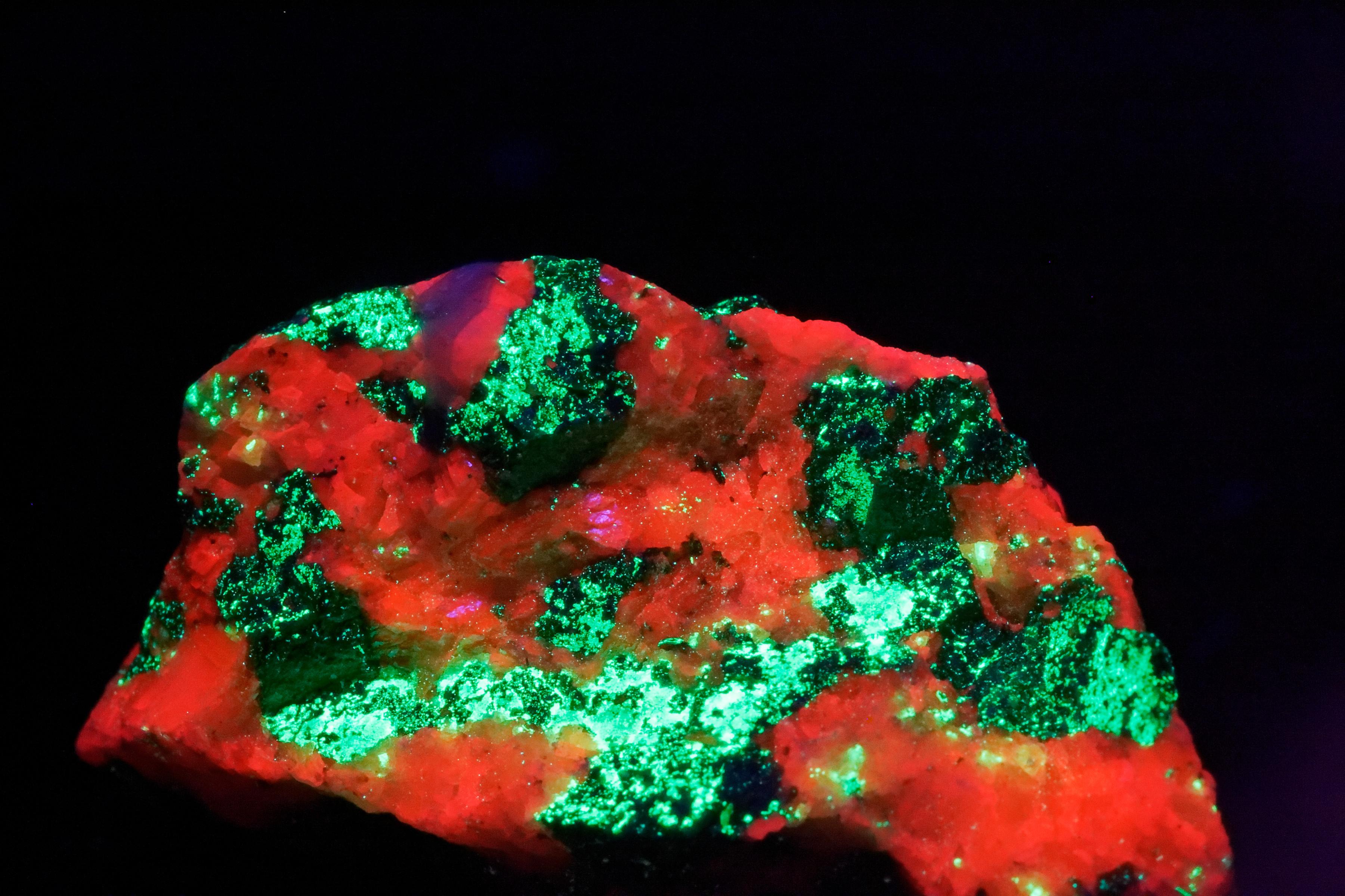
Youperlite
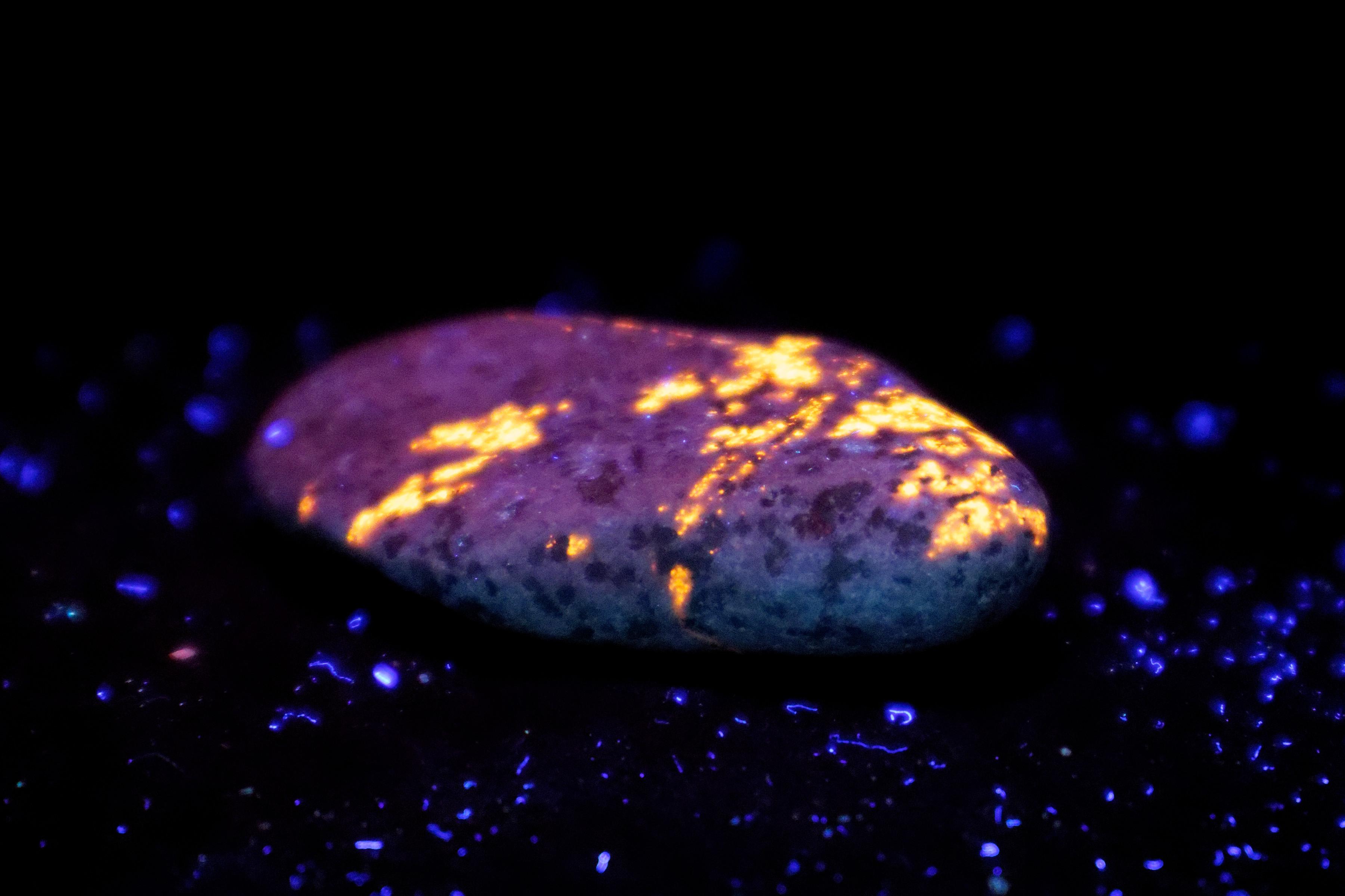
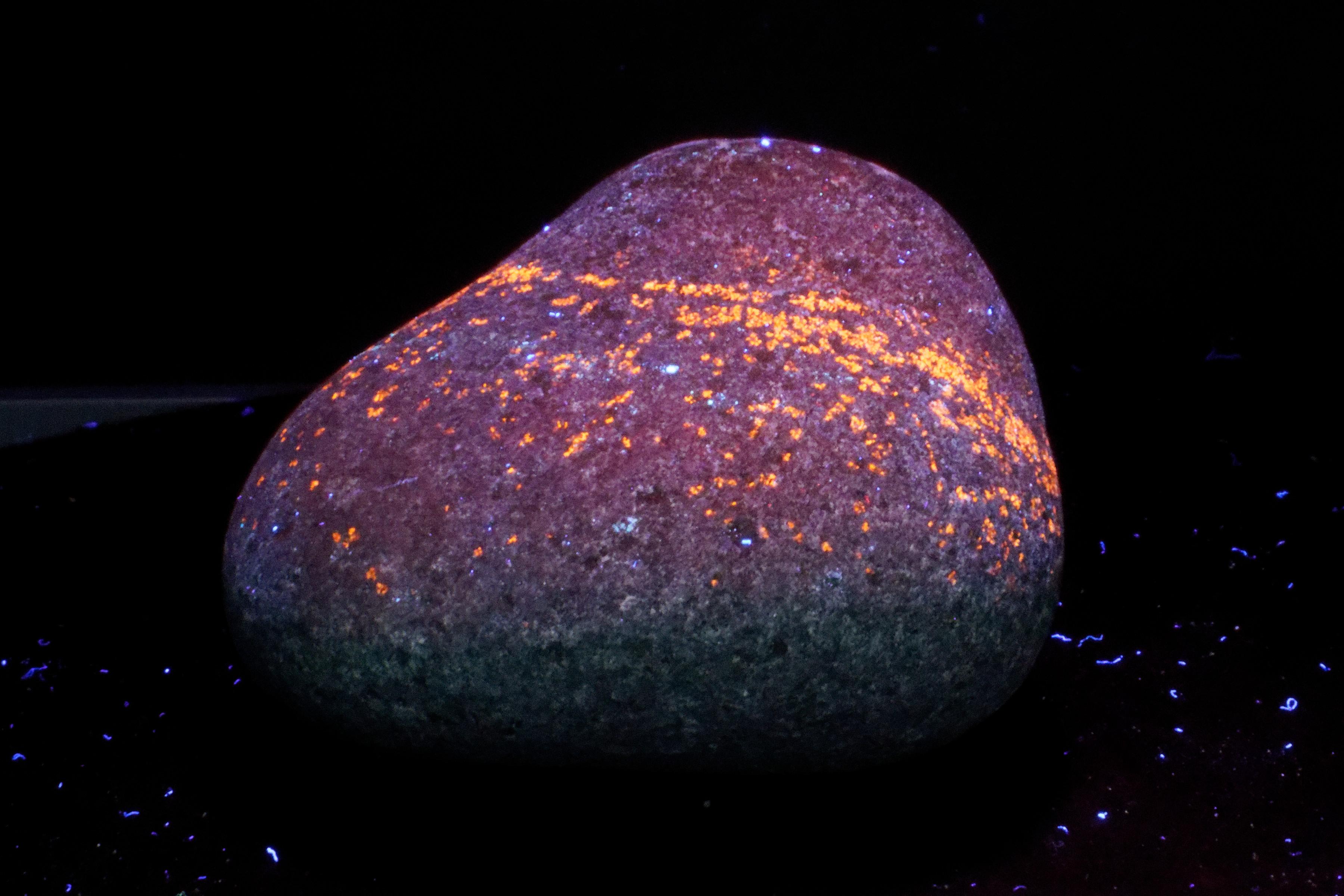
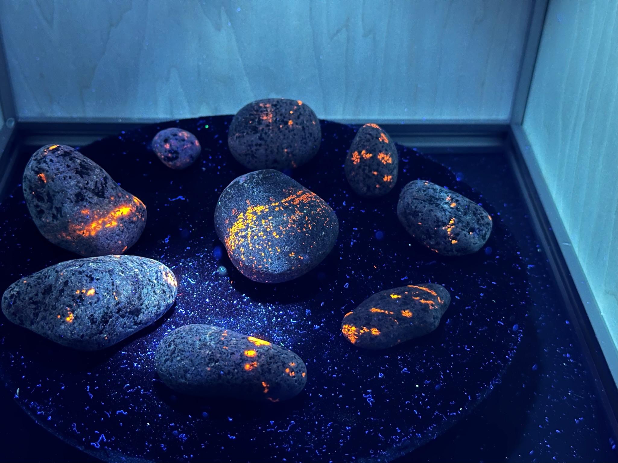
Ok, we live in Illinois, so we have to feature a local great lakes rock. Youperlite is a recent discovery, first found in 2017, and is common throughout the upper great lakes regions. You'll be able to read about it here or here. The flashlights we use were sold as Youperlites. We used them on nighttime beach walks on Michigan's upper peninsula.
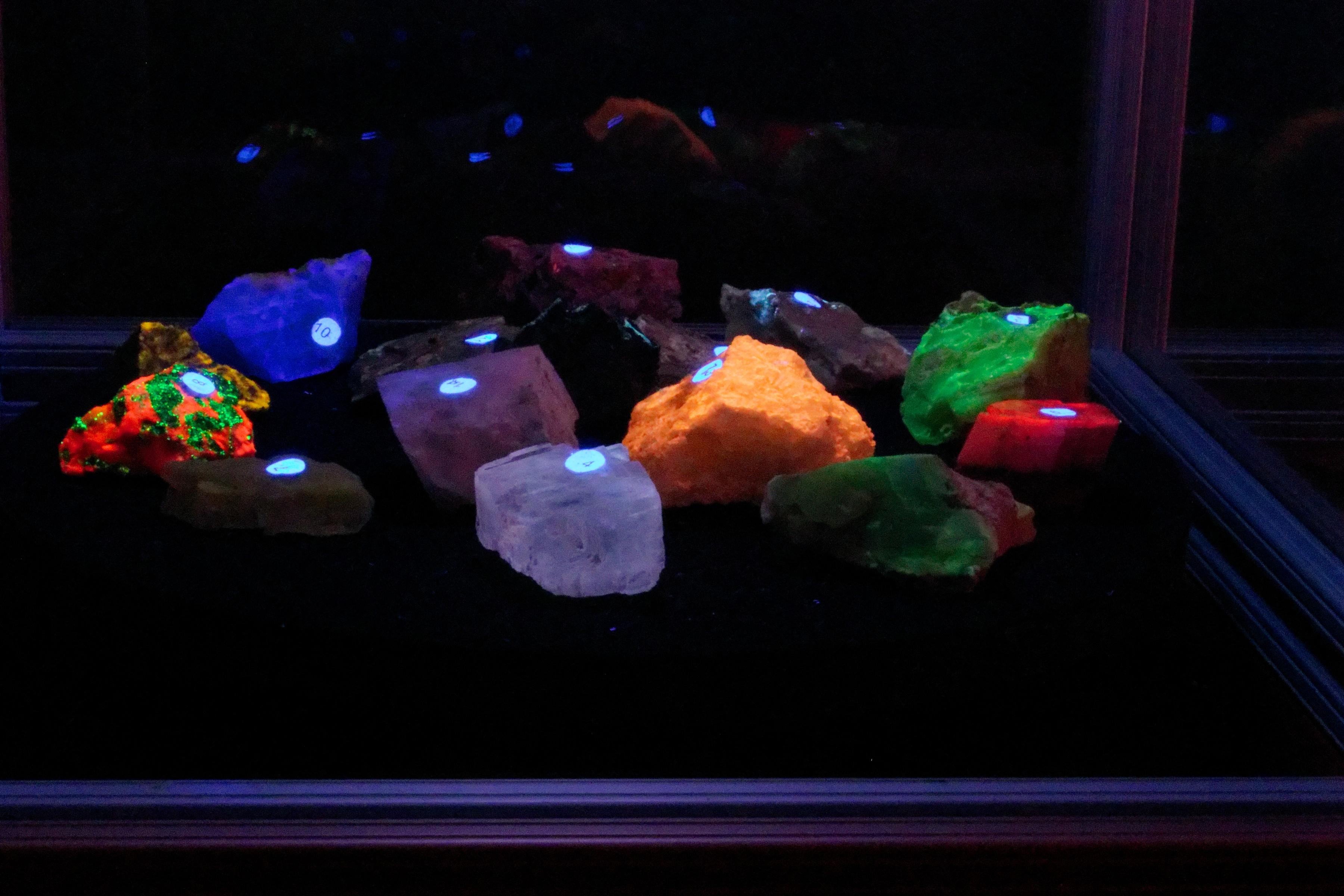
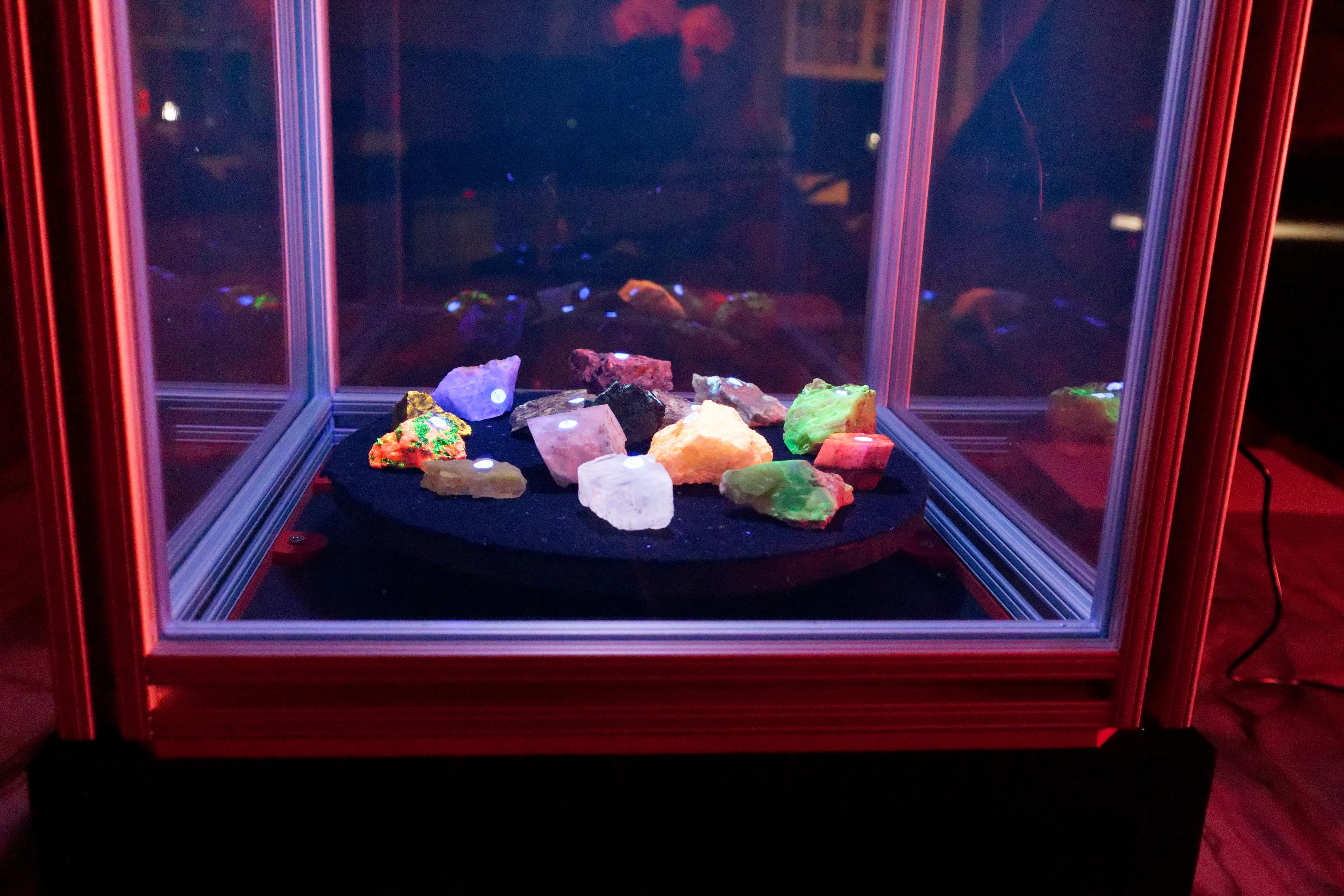
When You Are Not Doing Photography
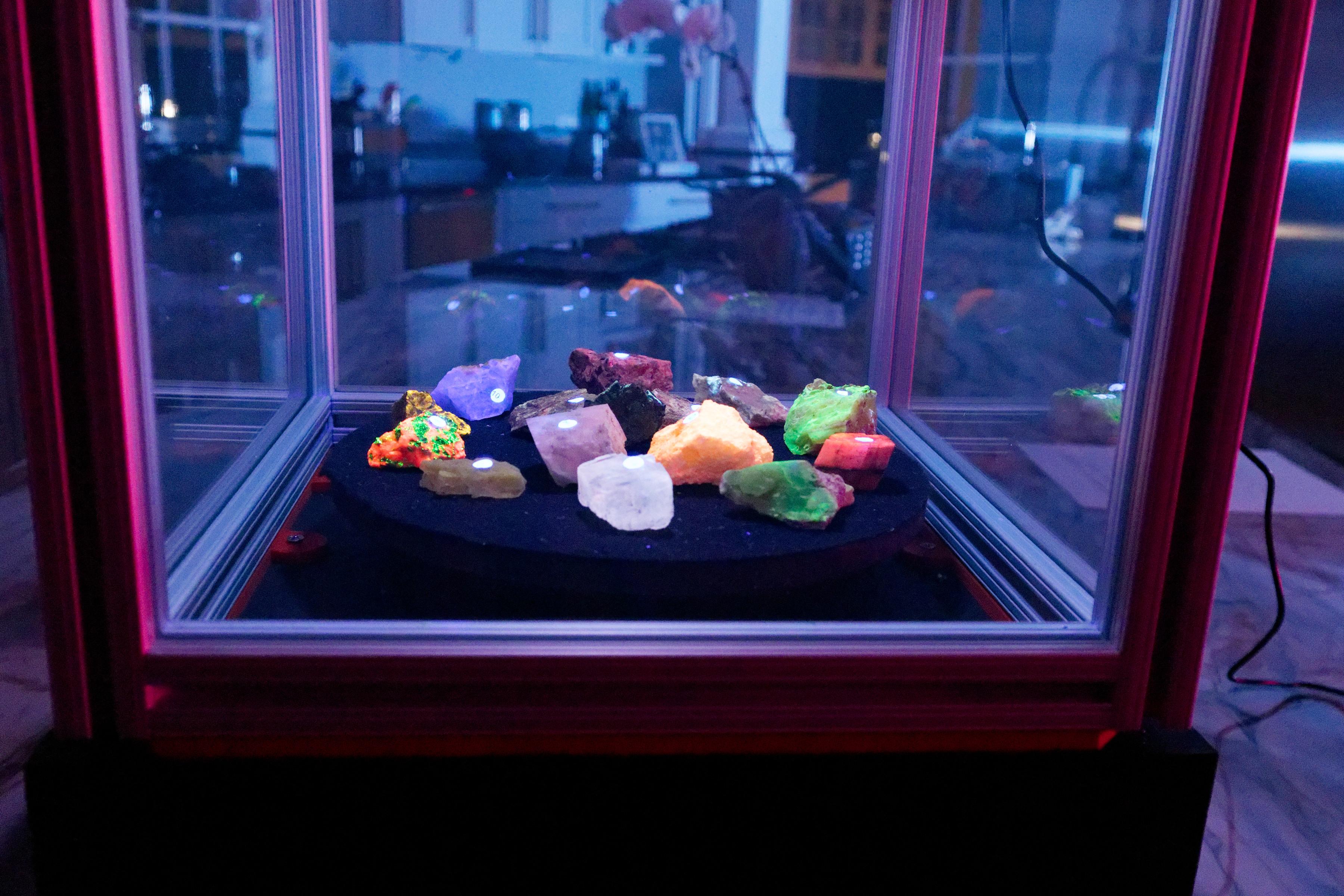
We have designed the dark box to be compatible with our display case. UVC is not transmitted through glass or polycarbonate. So by replacing the painted panels with polycarbonate sheets, the base can display some of your minerals under UVC light. The turntable rotates slowly when a control panel is not present, making it suitable for a display.
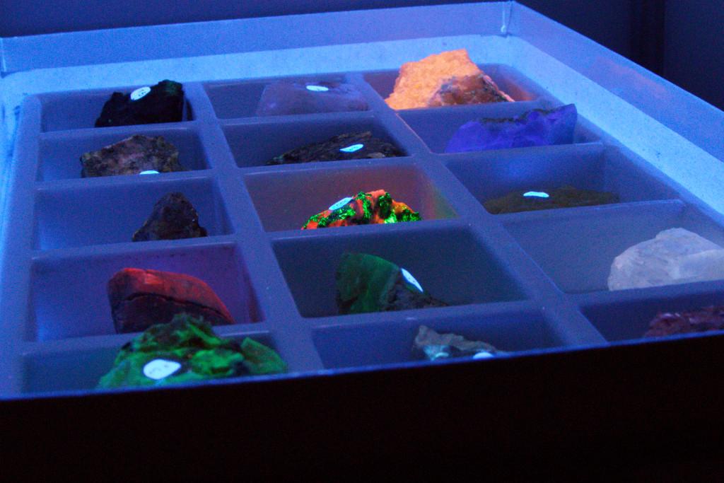
Our house has a set of polycarbonate panels and a top for a single 222nm light to replace the top lighting panel and the painted panels. It makes a great display case for our collection. We use the turntable to display large specimens and a stair-step set of shelves to display many individual smaller samples.
At Halloween, a taller box is used to display a fluorescent prop plant.
This is an area of photography that is full of discovery. You have the opportunity to explore the beauty of nature in a way that few people have experienced. It gives you new opportunities, from photography to finding minerals. ( Or other things. Some night, take a UV flashlight and walk through your kitchen in the dark. The oils and spices are a lot of fun. ) But what else can you do with this rig despite wanting to do photography all the time?
We hope you find some inspiration in the project, and thank you for reading.