Build a Rainbow Confetti Bot With a Raspberry Pi
by hazal mestci in Circuits > Raspberry Pi
318 Views, 0 Favorites, 0 Comments
Build a Rainbow Confetti Bot With a Raspberry Pi

Are you tired of dull celebrations with the same old confetti-popping techniques? You can now design your very own confetti-popping robot with a big red button that will make your parties a colorful blast, literally! With this robot, you’ll become the life of the party with just one press of a button. Whether it’s a birthday party, a wedding, a company launch, or just a random Wednesday night, this robot will add an extra dimension of fun and excitement to any event.
In this tutorial, you’ll learn how to build your rainbow confetti bot using Viam. This robot turns a motor when you press a button, which sets off a confetti cannon and makes confetti rain.
You can expand on this project to turn a motor based on other inputs, such as when a specific sensor goes high.
What inspired this project? When I first joined my current company a few years ago, everybody knew each other well (with 30ish people, it’s easy; with 100+, not anymore 🙂). We have a giant playground lab with 3D printers, robotics arms, soldering stations, and laser cutters where we can experiment and build, so we did much of that. Some earlier projects included robots closing curtains, opening doors, climbing poles, picking trash, and all kinds of other things. This was way before we launched GA; we were still in stealth, so I couldn’t brag about all the cool projects (yet). When we launched GA, it deserved a celebration, so this rainbow confetti bot came about!
Downloads
Supplies
Hardware
- A macOS or Linux computer
- A Raspberry Pi with a microSD card, set up using these instructions.
- A big button, like this one. Check the wiring diagram for the specific model you have as you wire the button.
- A mini confetti cannon like this one
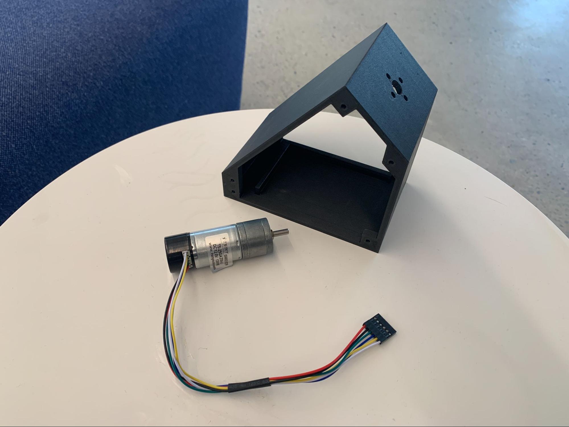
- A gpio motor. We used the Bemonoc 25GA370 DC Encoder Metal Gearmotor 12V. The STL files we use for 3D printing are adapted to the size of this motor, but you can update the design depending on your model.
- A L298N Motor Driver
- A 12V battery with a charger
- Jumper wires
- Alligator clips
- M2.5 x 16mm screws and M2.5 nuts
- A 2.4mm screwdriver
- a 3D printer and optionally a laser cutter (for the enclosure)
Software
Set Up Your Hardware
3D Print the enclosure
3D print the enclosure using these STL files. If you are using a different confetti cannon, you may need to adjust the size of the 3D prints to your confetti cannon size, as the wall thickness of the holder changes between brands. The same applies to the motor; if you use a different model, you can adjust the motor size so the holder fits your motor head.
Depending on your liking and the machine you have access to, you can either laser cut or 3D print the side panels.
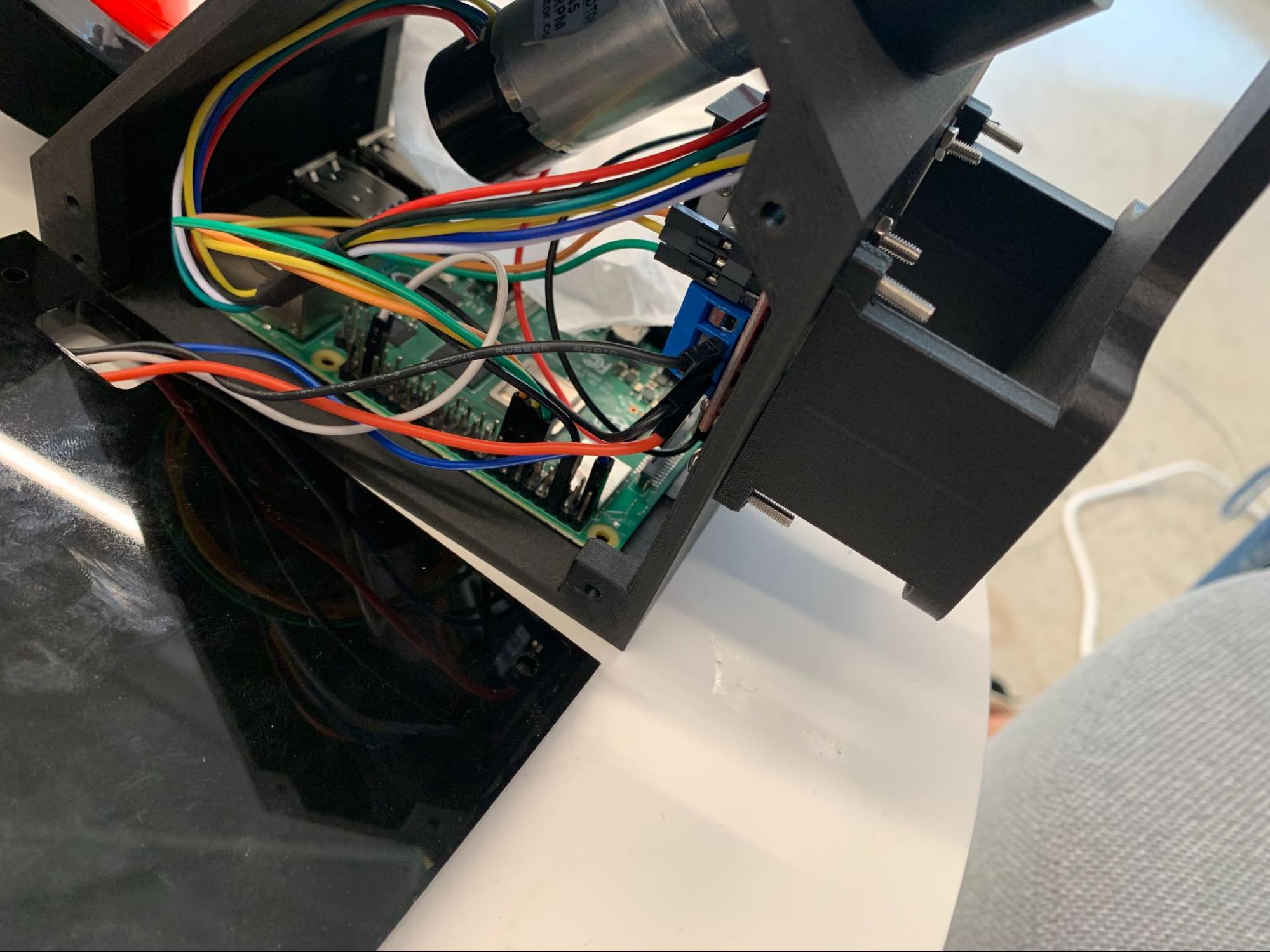
Wire your motor, motor driver, board, and the battery
First, attach your motor with screws to the middle of the enclosure. Attaching the motor first makes wiring the rest easier.
Because of the model I have, I only used two screws for the top, but some motors require four which is why the enclosure has four holes.
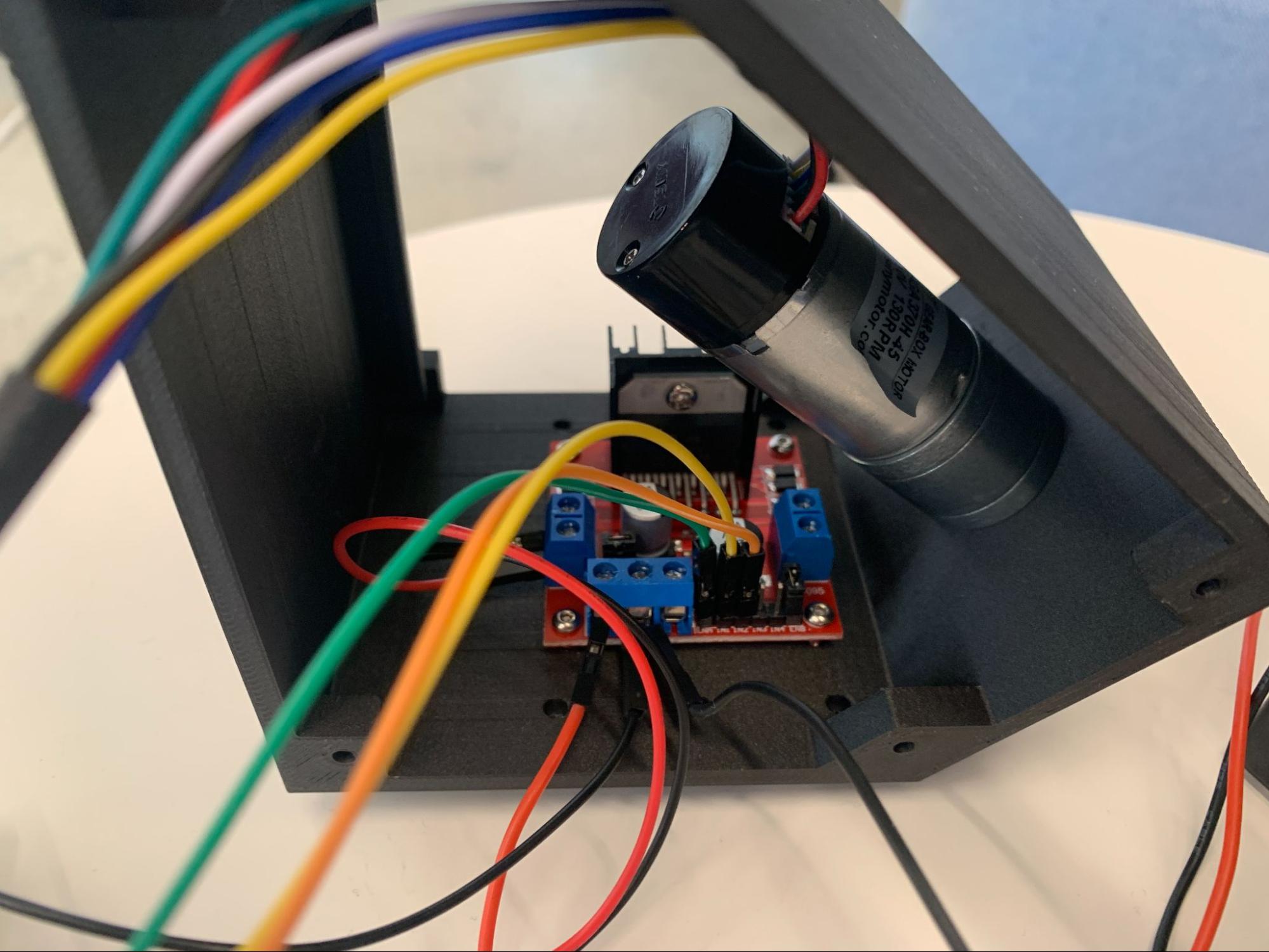
Now wire all of the components according to the wiring diagram:
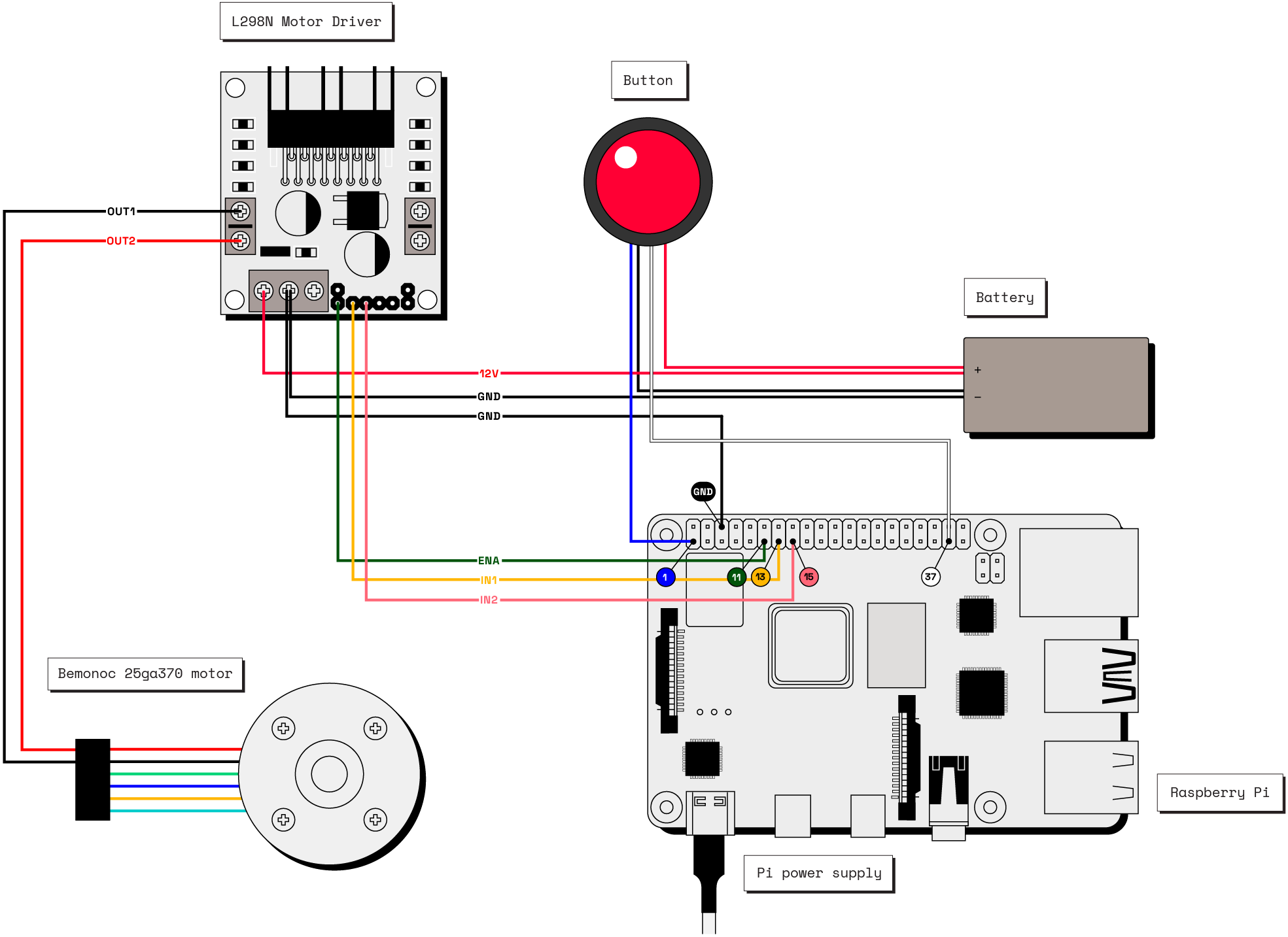
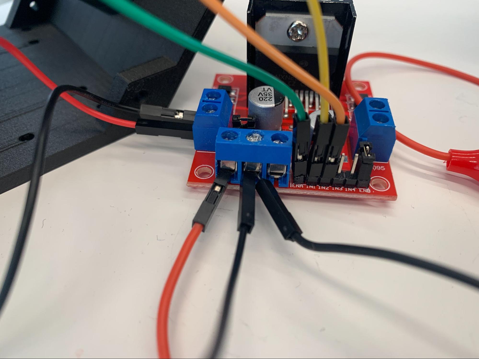
- Connect your motor to the motor driver. Several wires are coming out of the motor; connect the black one (ground) into the Out1 terminal and the red one (power) to the Out2 terminal and screw them in tightly (a 2.4mm screwdriver works well for this). After you have finished screwing the block down, make sure it is secure by gently tugging on the wire. If it is not secure, the wire will come out. You can leave the other wires disconnected.
- Connect your Raspberry Pi to the motor driver. Since you are using Out1 and Out2 on the driver, you need to use the corresponding inputs (In1 and In2), as well as a PWM pin. Select three available GPIO pins on the Raspberry Pi and connect them to the ENA (green wire in the wiring diagram), In1 (yellow wire in the wiring diagram), and In2 (orange wire in the wiring diagram) pins on the motor controller. Take the black safety cap out from the motor driver so you can use the ENA pin. Make sure to remember which GPIO pin on the Raspberry Pi you connected to each of these inputs. I connected Pin 11, 13, and 15, respectively.
- Connect your button to the Raspberry Pi. One connection goes to a 3.3V pin on the Raspberry Pi, and the other needs to be connected to a GPIO pin. We used Pin 1 for 3.3V (blue wire in the wiring diagram). Make sure to record which GPIO pin you connect to since you will be using this in your machine configuration. I used Pin 37 (white wire in the wiring diagram).
- Now, you can connect the button to your 12V battery and use a black alligator clip to connect the ground of the button switch to the ground of the battery. Then, from the same ground as the battery, use a black wire to connect to the ground pin on the motor driver. The ground of the motor driver will be shared with the Raspberry Pi, and your battery. Find a ground pin on your Raspberry Pi and connect it to the ground pin on the motor driver, allowing two pins to share the ground. Screw them tight with a screwdriver. I used Pin 6 on the Raspberry Pi as our ground pin, but you can use any Raspberry Pi ground pin.
- Now that you have grounded your robot, you can connect the motors to power. Use a red alligator clip to connect the battery to the button switch and another red alligator clip to connect the battery to the 12V input on the motor driver.
- Your robot wiring is now complete! Insert the microSD card into the Raspberry Pi and turn it on by plugging it into the wall.
Configure Your Confetti Bot With the Viam App
Now that your robot is wired, you must configure it on the Viam app before you can program it.
In the Viam app, create a new machine and give it a name. We named ours ConfettiBot.

Navigate to the CONFIGURE tab of your machine’s page in the Viam app.
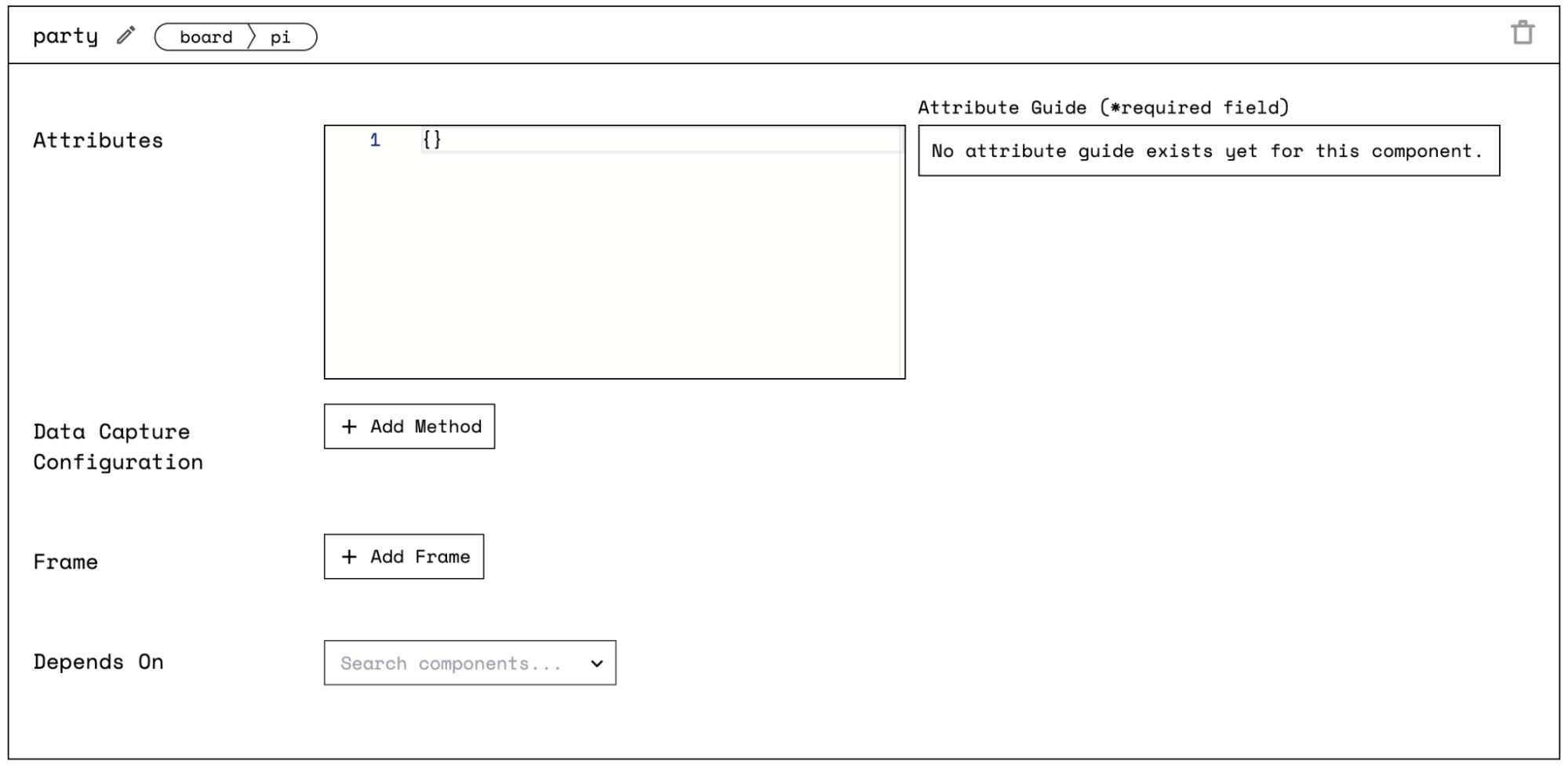
Configure the Pi as a board
Click the + icon next to your machine part in the left-hand menu and select Component. Select the board type, then select the pi model. Enter 'party' as the name and click Create. You can name your board whatever you want as long as you refer to it the same way in your code; I picked it for fun. Your board configuration should now look like this:
Configure the motor
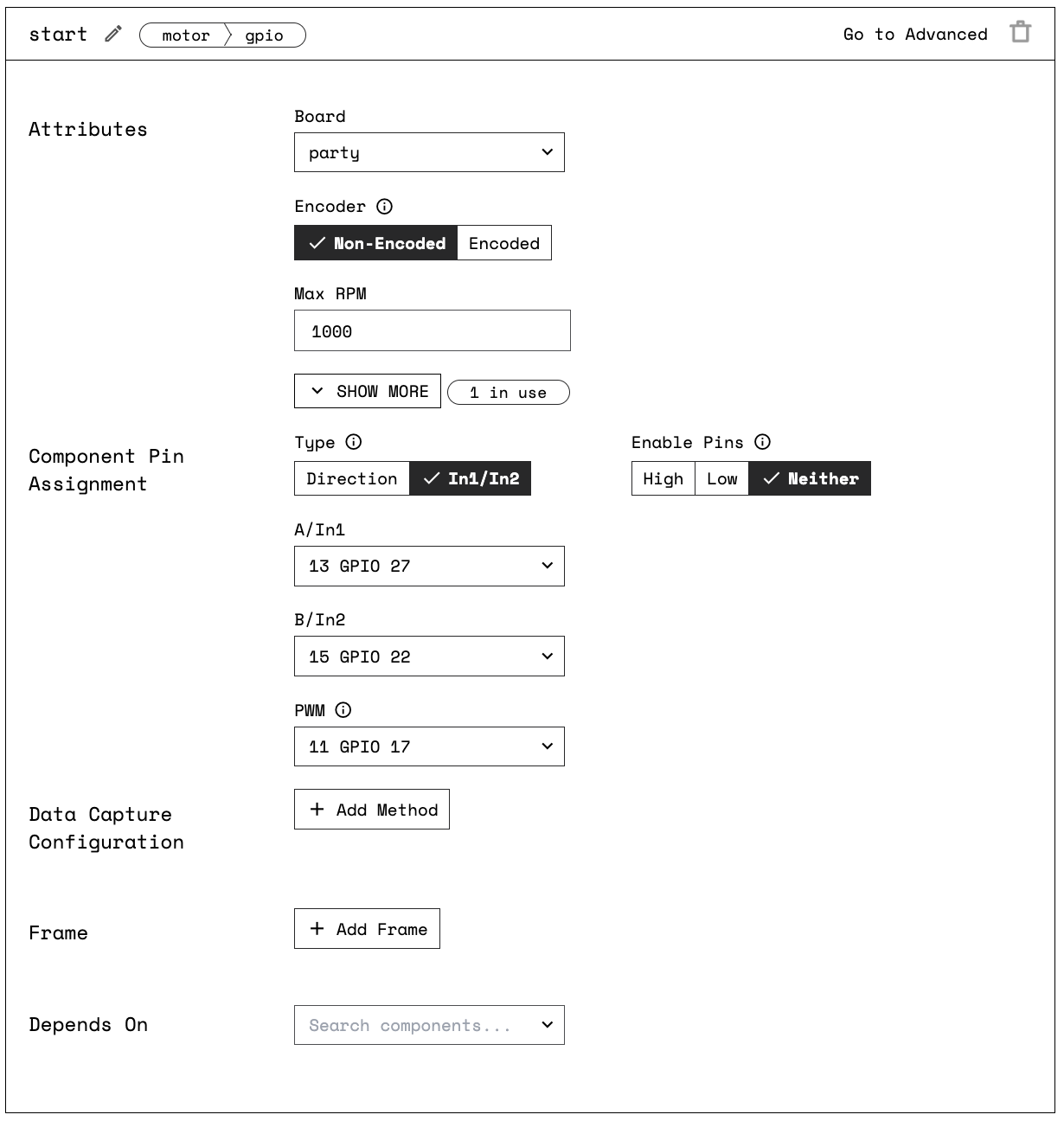
Click the + icon next to your machine part in the left-hand menu and select Component. Select the motor type, then select the gpio model. Enter start as the name for your motor component and click Create. I named it “start” to refer to the button being pressed, but this name is up to you as long as you remember the name and use the same name in the code later.
After clicking Create, there is a pin assignment type toggle. Select In1/In2 since that is compatible with the type of input our motor controller expects. In the dropdowns for A/In1 and B/In2, choose 13 GPIO 27 and 15 GPIO 22, and for PWM, choose 11 GPIO 17 corresponding to our wiring.
In the Board dropdown within attributes, choose the name of the board to which the motor controller is wired (“party”). This will ensure the board initializes before the motor driver when the robot boots up.
Click Save Config at the bottom of the screen.
Let’s test the configuration from the Control tab. Go to the board panel, set the pin connected to your motor (in this case, pin 37) to high, and your motor should turn.
Attach Components to the Enclosure
Now that you have tested your motor in the app and confirmed that everything works, you can finish assembling your confetti bot.
1- Attach the motor driver to the enclosure wall with four M2.5 x 16mm screws and M2.5 nuts.
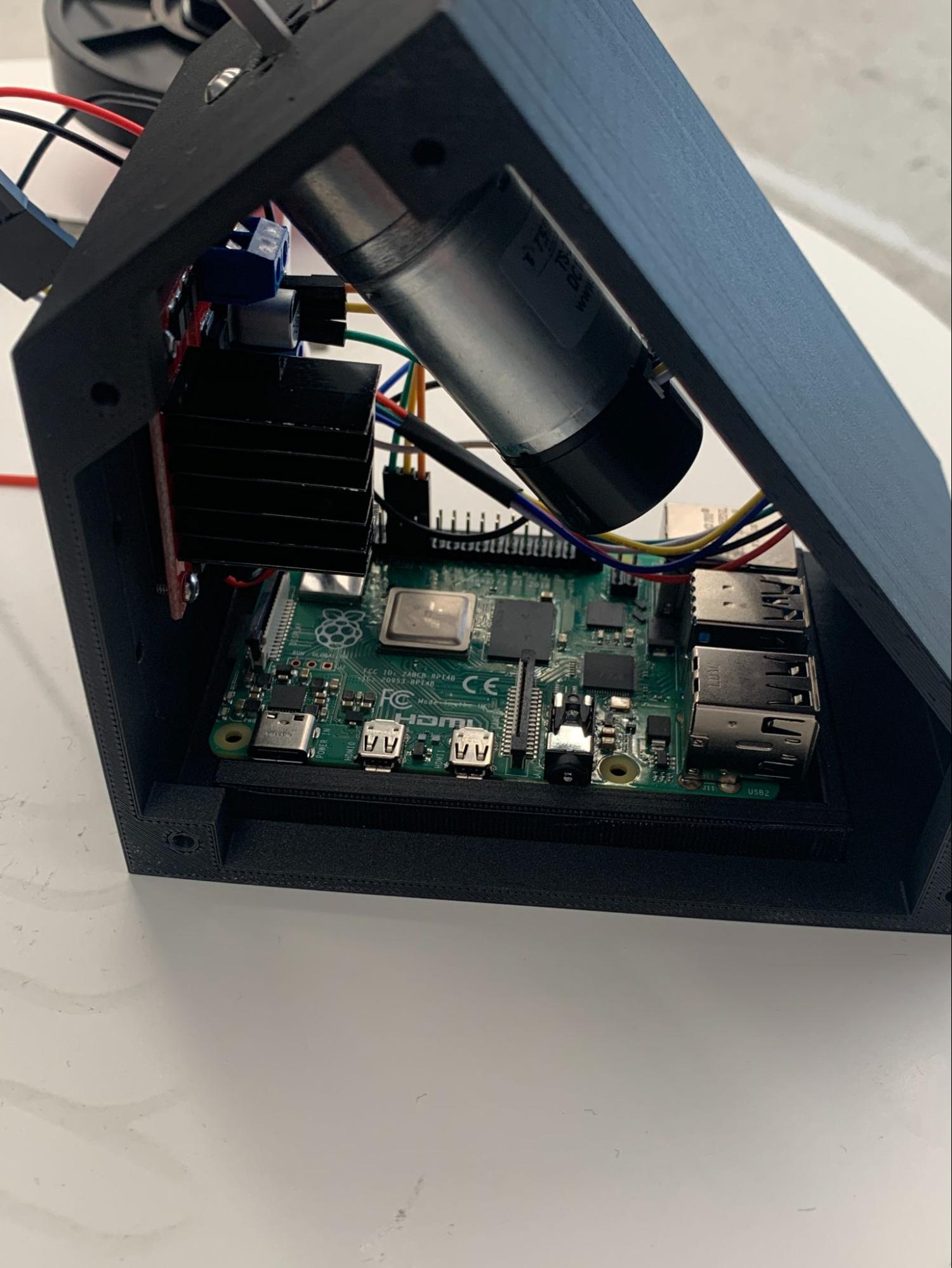
2- Slip the Raspberry Pi into the designated slot in the enclosure. Be careful of the wires during this processso they don’t pop off.
3- Add the confetti cannon to the enclosure by tightening the 3D printed holder around the confetti socket using one M2.5 x 16mm screw and an M2.5 nut. Then, connect the enclosure to the front panel.
4- Next, attach the 3D-printed circular holder to the base of the confetti cannon to hold its place, then to the motor. Secure the two together with a screw from the side. Depending on your motor size, you may need a different screw size.

5- Add the front section you just built to the rest of the enclosure using M2.5 x 16mm screws and M2.5 nuts. Make sure to do this step before closing the side walls to be able to access the slots for screws.
Optional: Laser cut or print the sides
Laser cut the sides of the enclosure and attach with screws. You can find the designs on Viam Labs’ GitHub.
If you don’t have a laser cutter, you can 3D print the sides instead or leave them empty.
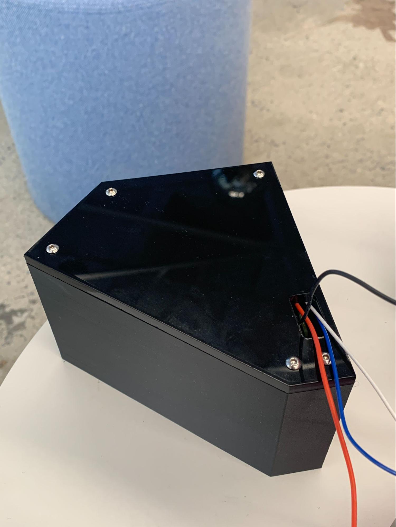
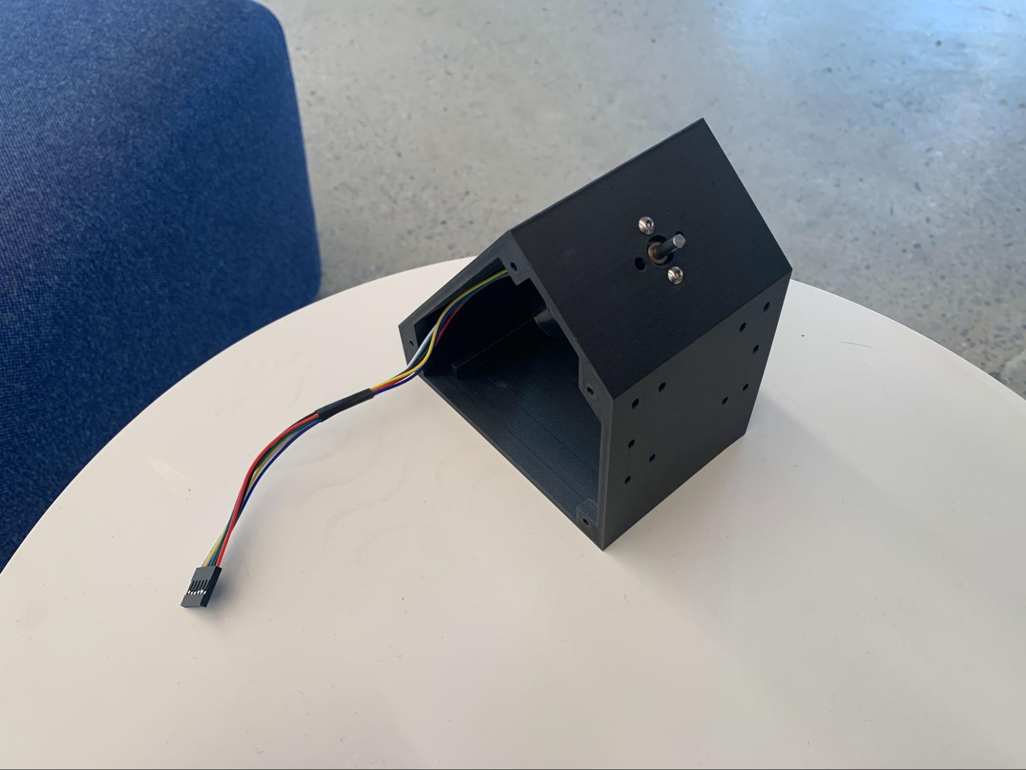
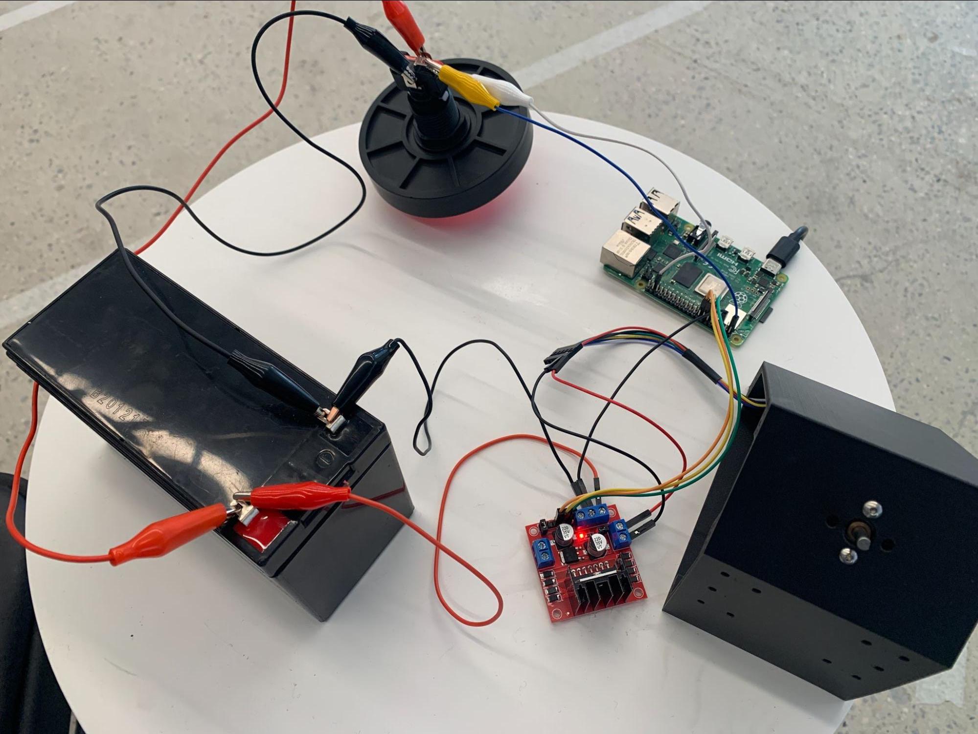
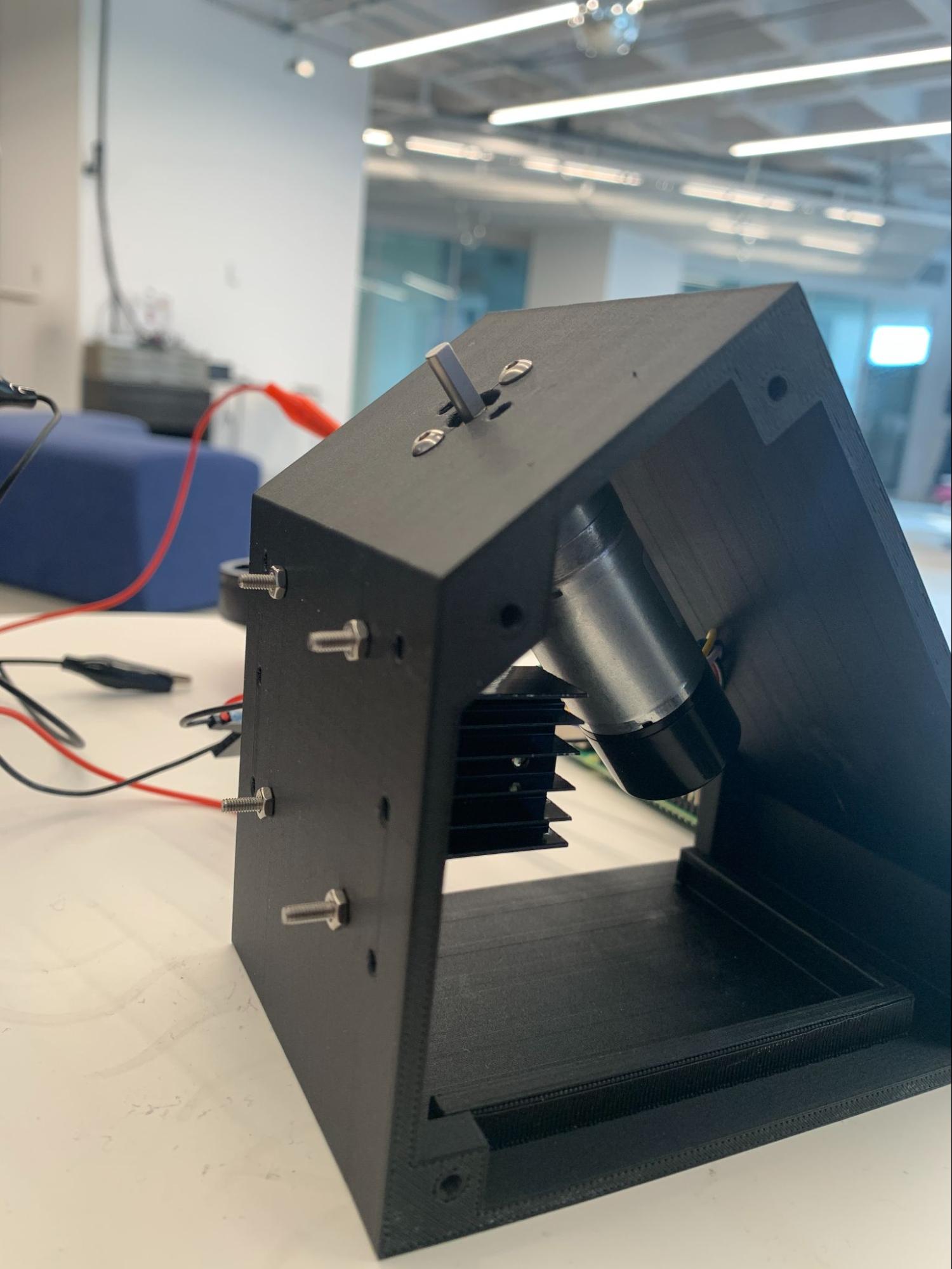
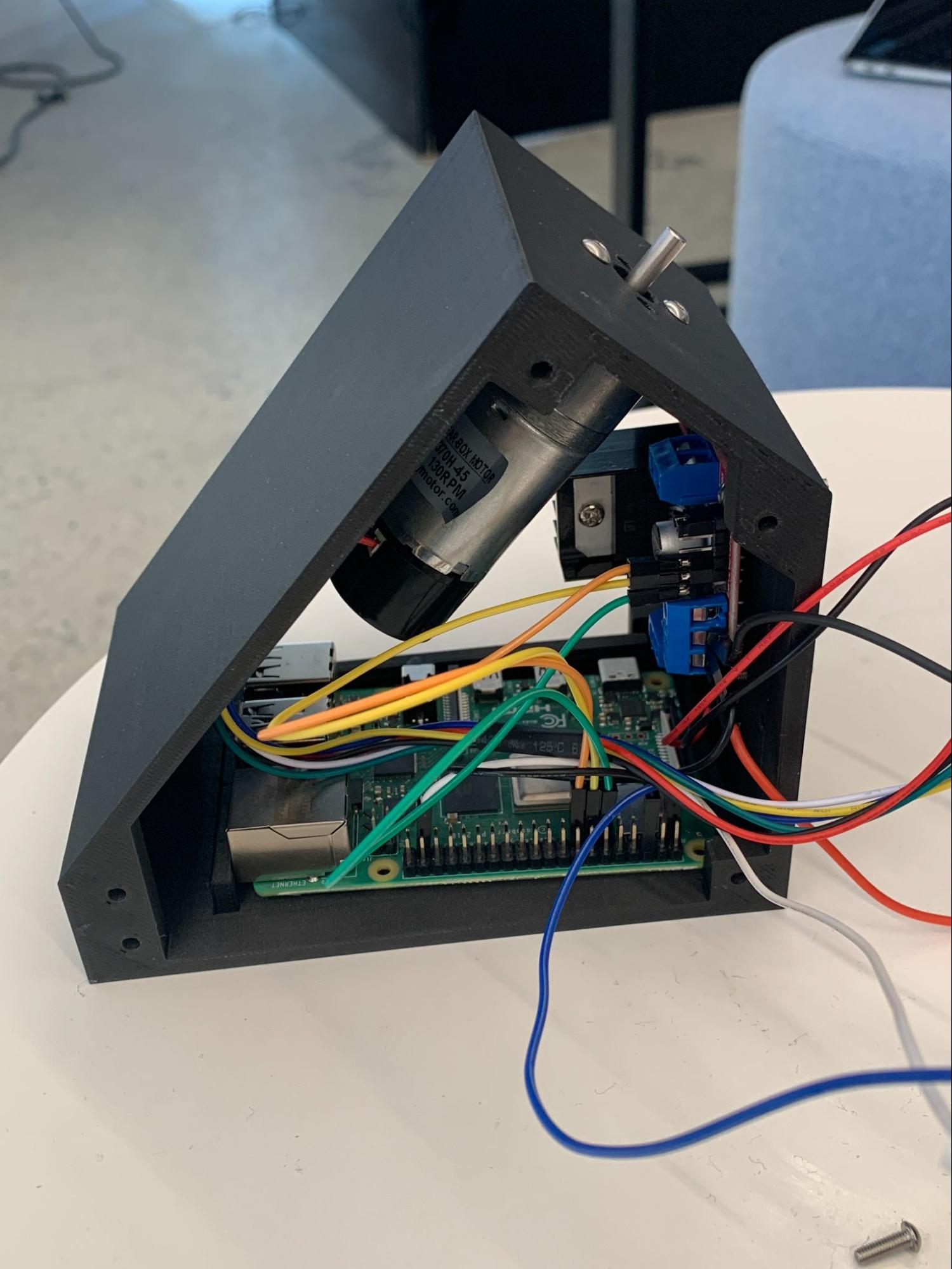
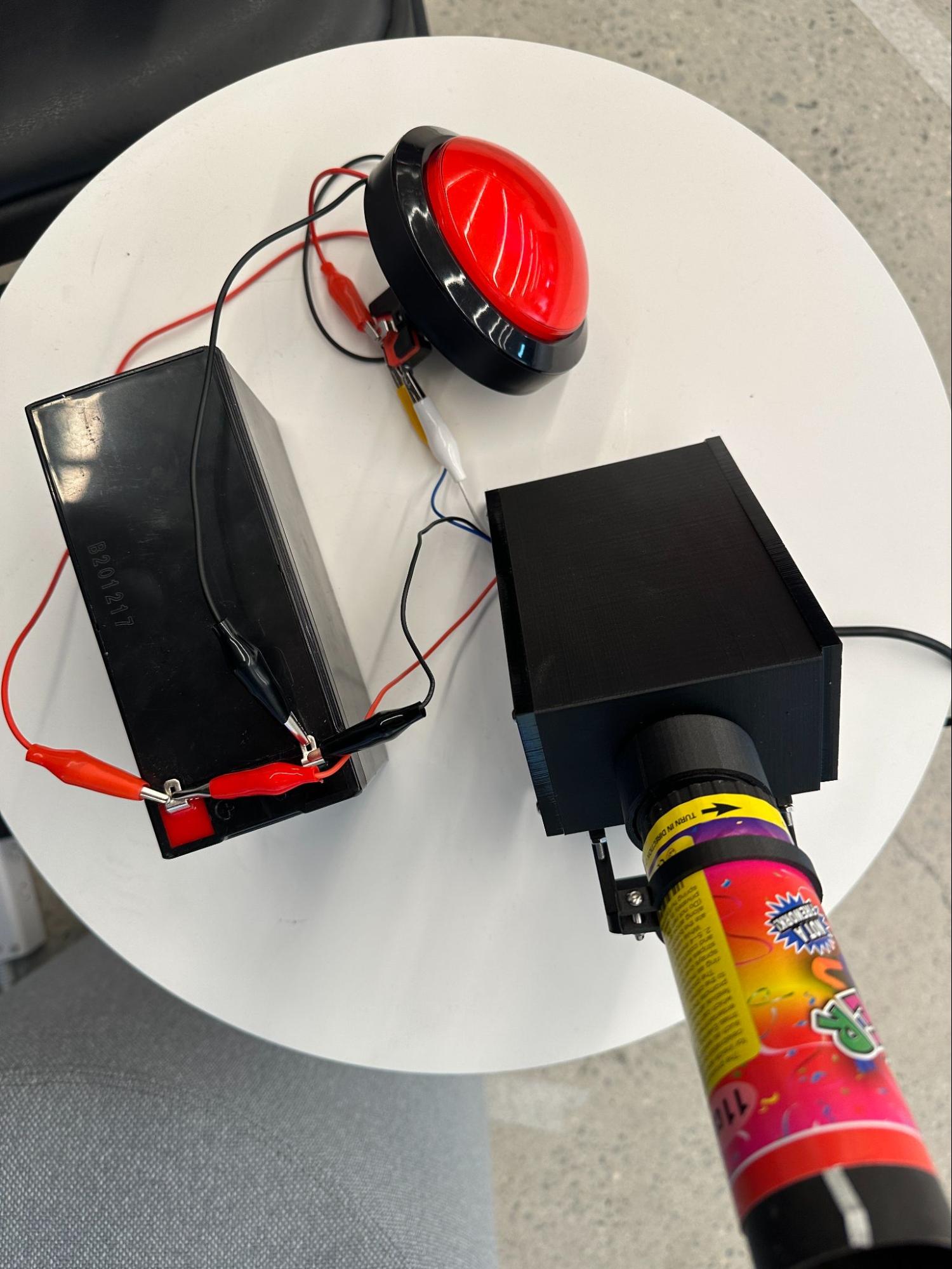
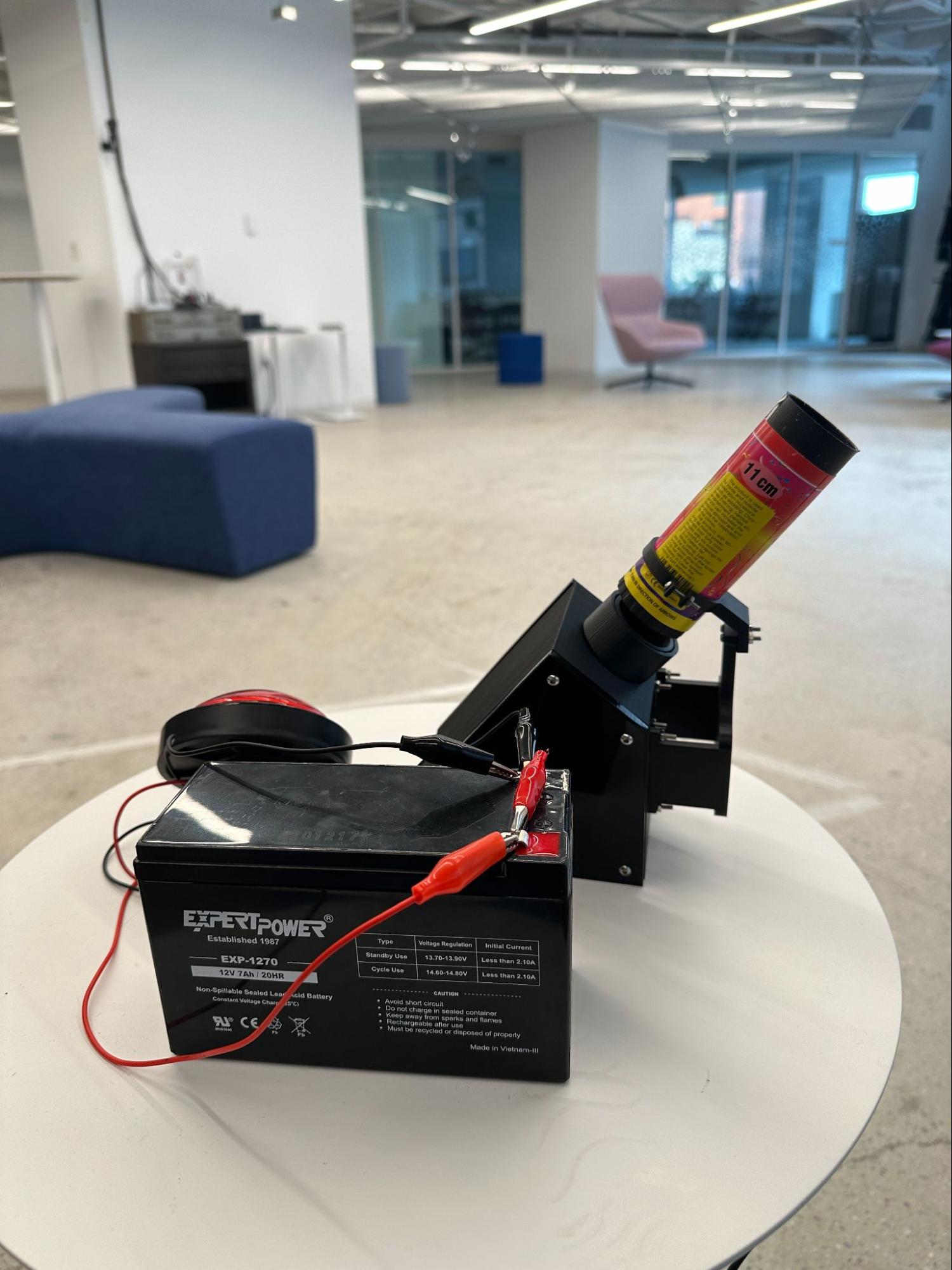
Final design
The final design, fully wired and put together, looks like this:
Write Python Code to Control the Confetti Bot
The following section explains the code for the confetti bot. The completed code for this project is available on GitHub. If you copy the code from this link, don’t forget to change your machine address and secret so it connects to your own confetti robot.
Navigate to the CONNECT tab on the Viam app, select Python as the language, and copy the sample code. Paste this into a new Python file in your favorite code editor to connect to your machine.
API KEY AND API KEY ID: By default, the sample code does not include your machine API key and API key ID. We strongly recommend that you add your API key and API key ID as an environment variable and import this variable into your development environment as needed. To show your machine’s API key and API key ID in the sample code, toggle Include secret on the Code sample tab. You can also see your API key and API key ID on your machine’s Security tab.
CAUTION: Do not share your API key or machine address publicly. Sharing this information could compromise your system security by allowing unauthorized access to your machine or to the computer running your machine.
At the top of the code, your board and motor components are imported:
from viam.components.board import Board
from viam.components.motor import Motor
In your main function add the following code, which instantiates a variable party as the board and start as the motor:
party = Board.from_robot(robot, "party")
# Note that the pin supplied is the pin we use. Please change this to the pin
# you are using.
party_return_value = await party.gpio_pin_by_name("37")
print(f"party gpio_pin_by_name return value: {party_return_value.get()}")

start = Motor.from_robot(robot, "start")
start_return_value = await start.is_moving()
print(f"start is_moving return value: {start_return_value}")
The only other code you need to add to your main function is a while loop to check if the button is being pressed. Copy this code and add it to your own code within the main function block:
while True:
    print(party_return_value.get())
    while (await party_return_value.get()):
        await start.set_power(.8)
        await asyncio.sleep(0.1)
        if not (await GPIO.get()):
            break
    await start.set_power(0)
This is all the code you need to activate the gpio pin and turn the confetti cannon attached to your motor!
Next Steps


Woohoo! You learned to turn a motor when pressing a button, setting off a rainbow confetti cannon. You could use this concept for any simple robot that turns a motor when a pin on the Raspberry Pi goes “high.” One example of this logic would be connecting a PIR sensor to a Raspberry Pi. You could then make a motor turn whenever you sense someone walking by. Or, you could incorporate a camera and machine learning capabilities to automatically release confetti when a specific person approaches your desk, surprising them on a good day and scaring them on a bad one.
Why did I choose to use a Raspberry Pi? It's due to its versatility and ability to function as a compact and affordable computing platform. While studying Design and Technology in college, I extensively tinkered with Arduino boards and Raspberry Pi, thoroughly enjoying the experience. The Raspberry Pi is well-known in the DIY technologist community for its ease of use and diverse applications. Given my familiarity with the board, it emerged as the ideal choice for a hardware integration project. It's worth noting that Viam software supports a variety of computing boards, including BeagleBone, SK-TDA4VM, Jetson Nano, and Intel UP4000. Therefore, technically, most single-board computers could function effectively for the Confetti Bot.
In this context, the Raspberry Pi provided the necessary computing power to control the button, motor, and other hardware components involved in triggering the confetti. Its GPIO (general purpose input/output) pins made it convenient for interfacing with various electronic components, allowing me to program and control the actions of the Confetti Bot. Moreover, the Raspberry Pi's robust community support and extensive documentation enhanced accessibility for me and potential users following the tutorial.
What were the most significant challenges for me, and how did I overcome them? Fitting all the components inside was the hardest part. I had to design multiple enclosure versions and test the prototype many times. I also did not know that not all confetti cannons are the same size, so even between brands, sometimes the clasp wouldn’t hold the cannon firmly, and the cannon would turn with the motor without popping anything. So that required a few iterations, too. The cables to the battery are still hanging out, so version two will hopefully enclose everything :)
Bonus: I added some extra renderings of the 3D design from Solidworks for my 3D design geeks.
Bonus bonus: This article was published in The MagPi #136. You can buy it or view the PDF here.