Build a MikroVice - Portable, Multi-Functional, DIY Woodworking Vice
by Door County Rustic in Workshop > Woodworking
2967 Views, 85 Favorites, 0 Comments
Build a MikroVice - Portable, Multi-Functional, DIY Woodworking Vice

.JPG)
.JPG)

.JPG)


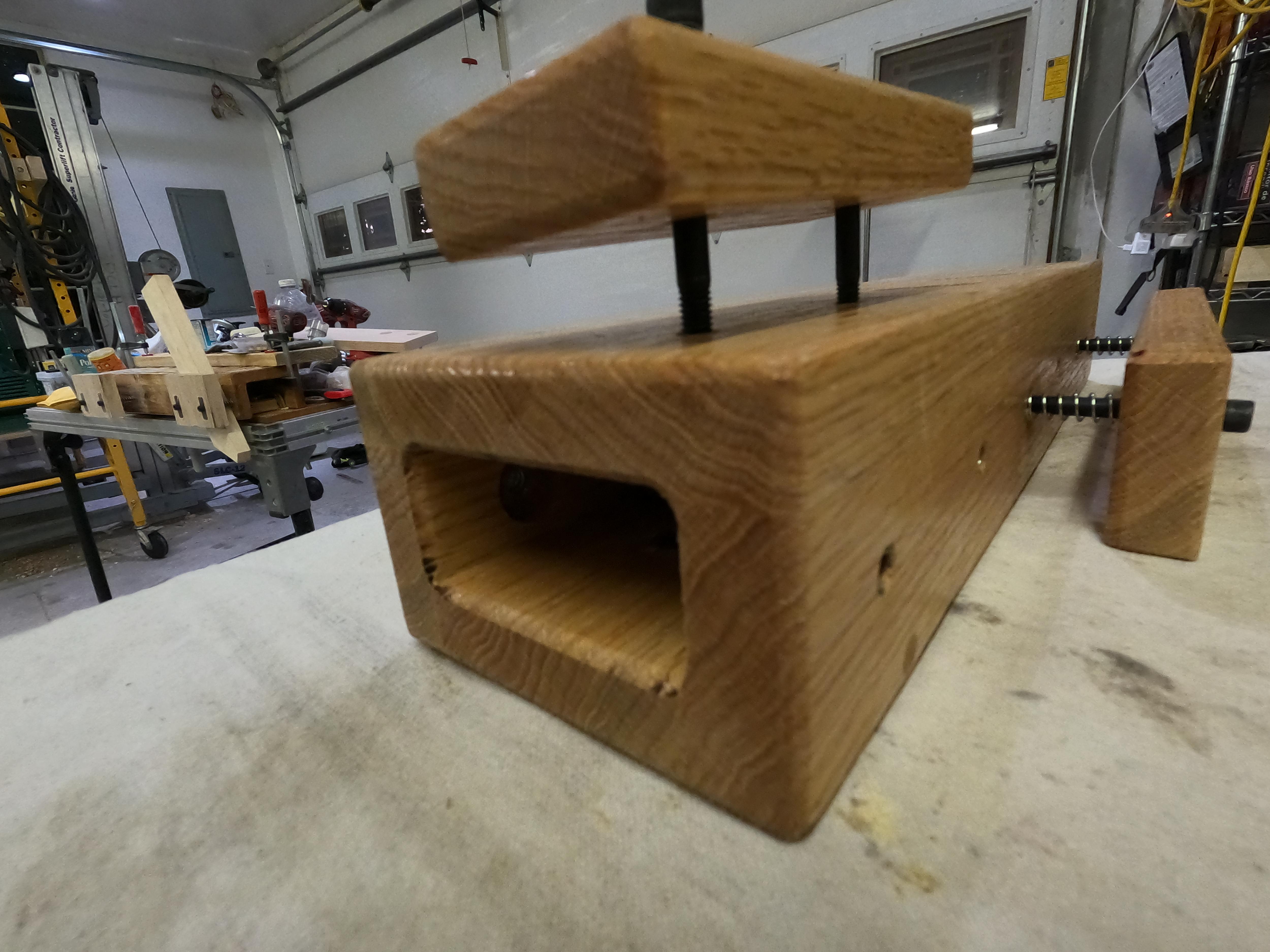
Since I needed a class project that would challenge both the advanced woodworkers AND be buildable by the newbies AND doable in a 4-Hour workshop AND cost students less than $75 AND I wanted some smaller ones to take camping AND since every woodworker needs a good woodworking vice the MikroVice arose out of the sawdust!
Small But Functional and Heavy Duty
After several prototypes it became clear that a "Pro-Level" woodworking vice was very doable AND could be built with DIY simplicity for under $50. Some of the key features include:
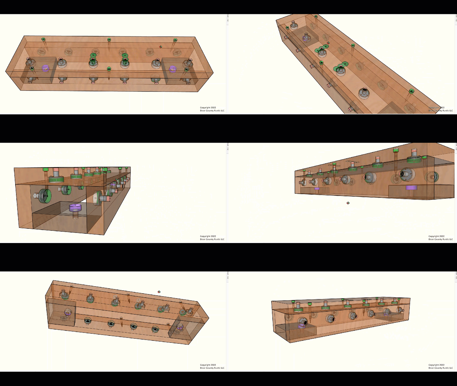
- The main "BOX" with a series of strategically located holes
- Threaded metal nuts permanently mounted in those holes
- Multiple vices in lengths of 21", 14", and 7" for various tasks
- Compression Springs to protect the workpiece from contacting bolt threads
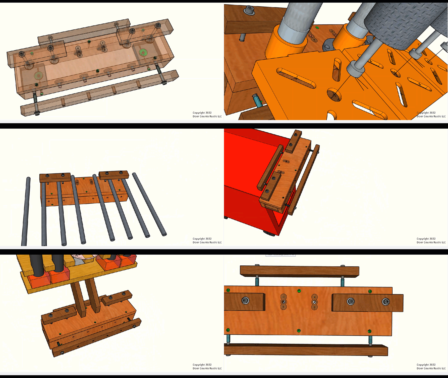
- Vice mounting locations on front, back and top
- Multi-Tasking those vices to hold 3rd party pipe clamps, bar clamps and R&R Clamps
Mounts Anywhere
With integrated threaded metal connectors the MikroVice can be mounted just about anywhere and to anything. This is the perfect solution for woodworking in condos, apartments, storage units and yet strong and tough enough to be taken to construction jobsites for attaching to bare studs or scaffolding.
- Integrated mounting to Festool Multifunction Table or Kreg Mobile Project Centers
- Integrated mounting to Harbor Freight Rolling Tool Cart
- Integrated mounting to Scaffold or Truck Bed Extenders
- Integrated mounting to any slotted surface like a picnic table in a National Park
Multi-Tasking
Once the MikroVice is mounted to a solid surface then other tools can be mounted on it including:
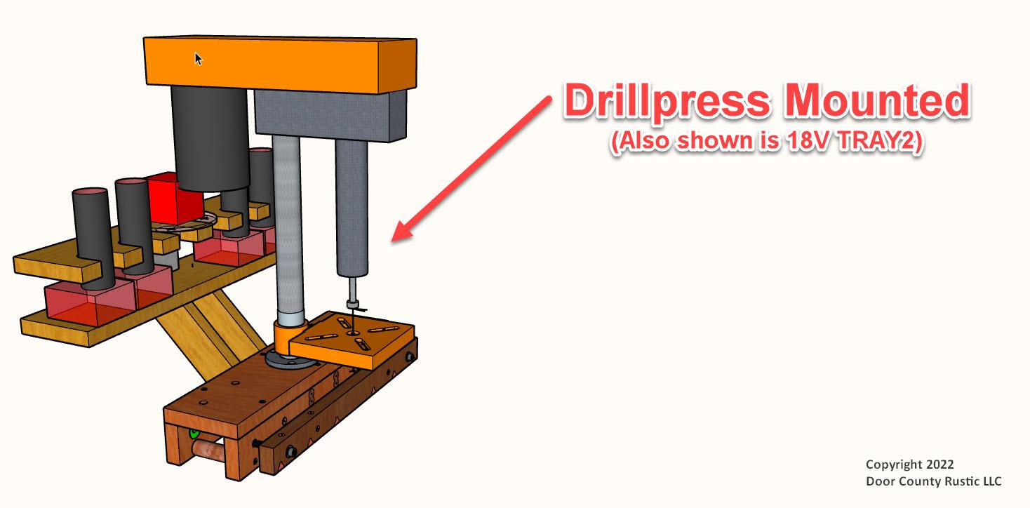
- Integrated methods for mounting up to 3 small light-duty drillpresses simultaneously;
- Integrated methods for mounting two medium duty drillpresses
- Integrated methods for mounting Kreg (or other brand) Pocket Hole Jigs
- Integrated methods for mounting small miter saws or bandsaw
- Integrated methods for mounting to 16" O.C. wall studs (bare or finished)
- Mountable vertically or horizontally with vice functions in any direction
Super Easy to DIY Build
During prototyping I was constantly tempted to use some of the pro-type tools in my workshop (Shapers, Dominos, large drillpress, etc.) but kept returning to "could this be built by a newbie woodworker using basic hand-held power tools in the kitchen of their condo?". I am pleased to say "Yes"! So not only is it a project anyone can build the end product, the MikroVice, then becomes the "tool" to build even more projects easier, quicker and safer. That said, there are plenty of opportunities for very experienced woodworkers with shops full of high-end tools to expand and enhance the project for even more functions, mounting options and appearances.
Affordable
The MikroVice, including the 3 Vices, can be built from one off-the-shelf 1 x 6 x 8' hardwood board costing about $45 plus about $20 in hardware.
Appearance
The MikroVice was not only designed to be functional and strong it was also designed to look GREAT! The recommended hardwood is a step in that direction but maybe substitute black walnut, wormy maple, rustic cherry or other species and these little guys are great to build as heirloom quality gifts.
A Skill Builder for Newbies and Pros Alike
Wow! Was this an eye opener relative to countersinks and counterbores! As the project developed into a "drillfest" attempting to accomplish a wide range of tasks with as few power tools as possible the research into specialty drill bits, countersinks and counterbores intensified. If you are new to woodworking building this project will introduce several bits and methods that can be used on future projects. Even if you are an experienced woodworker it may be worth checking out the Steps relative to "Counterbores and Countersinks.
Conclusion?
After building and using several MikroVices my only regret was not having built these decades ago for professional work in my shop, on jobsites and to woodwork when RV camping!
Supplies



Lumber
- One 1 x 6 x 8' oak board currently available at Menards for $42.71
Hardware for Assembly and Vices
- 10 - GRK R4 #9 x 2" Fastener
- 16 - 5/16" Screw-On Tee Nuts
- 6 - 5/16" x 3 1/2" Socket Cap Bolts (Enough for 3 Vices)
- 6 - Compression Springs (Enough for 3 Vices)
Recommended Bits
All of these are quite capable in hand-held cordless drivers:
- Snappy #43008 1/8" x 3/8" Countersink
- Snappy #43018 1/8" x 1/2" Countersink
- T-25 Star Bits (to drive the GRK #9 screws)
- 1 1/4" Famag Bormax 2.0 Forstner Bit (with Hex Shaft)
Power Tools
Since I plan to build more of these MikroVices when we are camping I wanted to make it so it could be built with just the tools I take with on those trips:
- Milwaukee 7 1/4" Sliding Miter Saw (but a circular saw would work)
- Milwaukee 18V Table Saw (but a circular or track saw would work)
- Milwaukee 12V and 18V Drivers, Impacts and Routers (but 120v will work)
Hand Tools
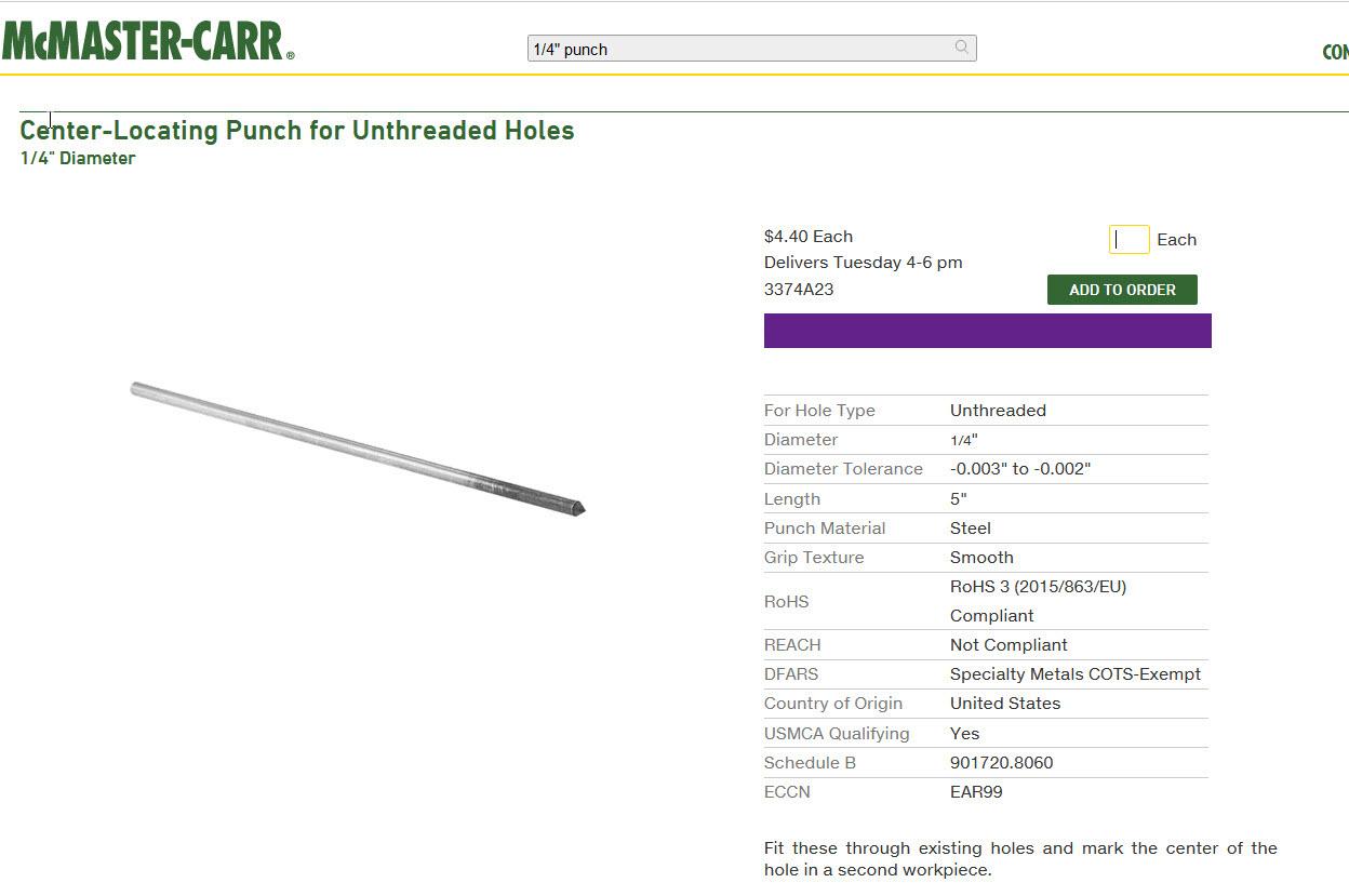
- 1/4" Metalworker's Punch (to "dimple" for drilling)
- Eklind 1/4" x 6" Cushioned T-Handle Allen Wrench (for operating Vices)
Hardware Kits and Templates Available
Links above point to 3rd party online or physical stores where those items can be purchased. (BTW I do not receive compensation for those links). Unfortunately no single source carries them all so multiple shipping costs can add up. Because many of my projects are intended as class projects for woodworking workshops that I teach or that I build as gifts, demos, prototypes or for resale I buy hardware and small tools in bulk. Buying in bulk allows me to create "Project Kits" for students in my workshops. If requested by readers here at Instructables.com I can post those kits on Etsy or Shopify?
Design Criteria

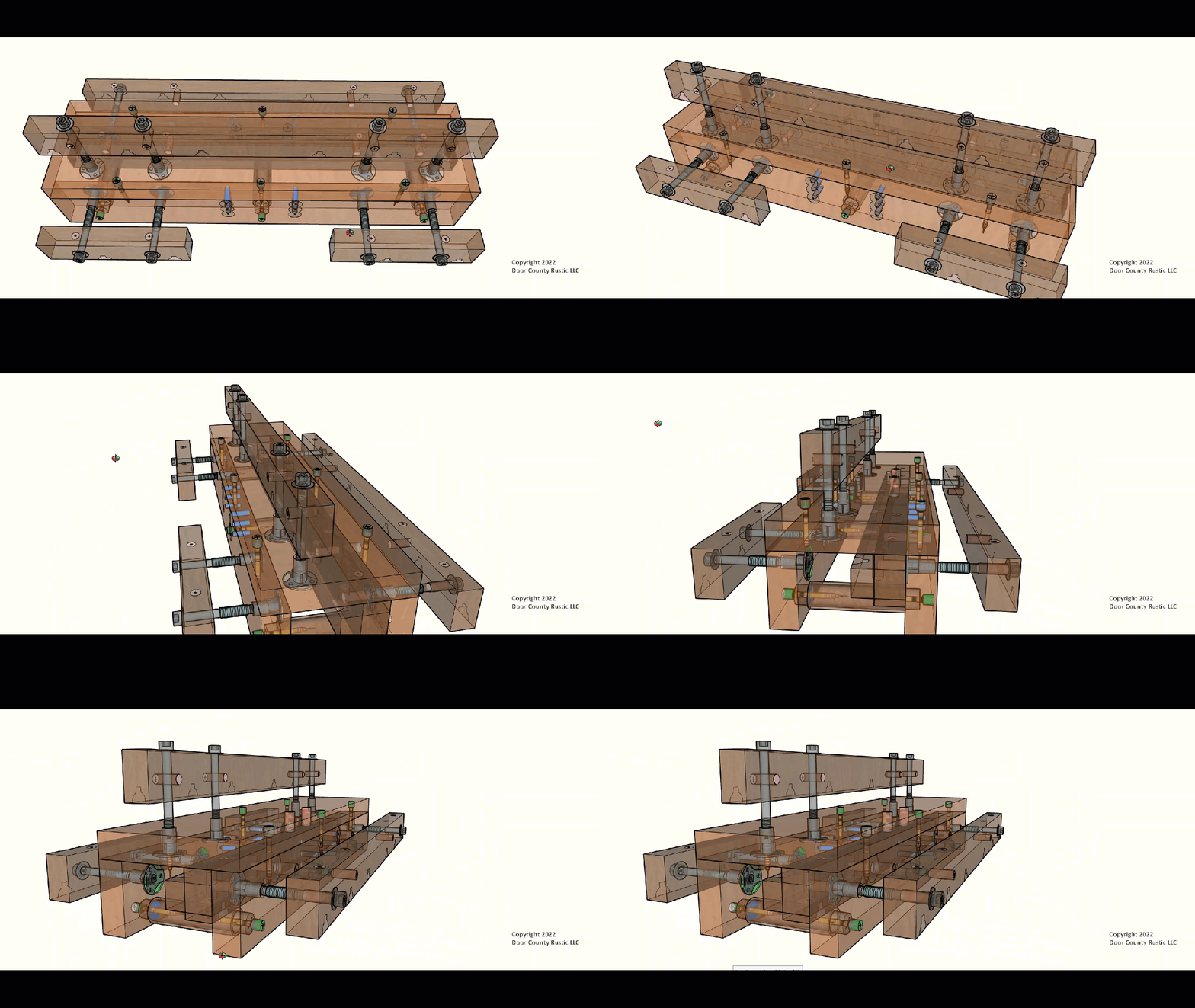


Before putting pencil to paper (actually fingers to keyboard) I made a "wish list" of criteria based on:
- Functions the MikroVice would be asked to perform
- Methods for Mounting the MikroVice to use those functions
- Skill-Levels relative to the spectrum of woodworkers in my workshops
- Cost and Availability of Materials considering current supply chain issues
Functions Criteria
- Include locations for at least 3 Vice Boards
- Include methods to simultaneously mount up to 2 light-duty 8" drillpresses
- Include method to mount one heavy-duty drillpress
- Include methods for attach 3rd party pipe, bar and R&R Clamps
- Include methods to attach a Rikon 10" drillpress
- Include methods to attach a Kreg or other Pocket Hole Jig
- Include methods to attach a 7 1/4" 18V Sliding Compound Miter saw
Methods for Mounting Criteria
- Integrate quick mounting to Festool, Kreg or other 4" O.C. Dog Hole Workstations
- Integrate quick mounting to rolling carts like the Harbor Freight Rolling Tool Carts
- Integrate quick mounting to common scaffolding used on construction sites
- Integrate quick mounting to the 2" receiver on a vehicle via a Truck Bed Extender
- Integrate quick mounting to picnic tables typically built with 3/8" gaps between boards
- Integrate quick mounting to any table top or flat surface that can be clamped to
- Include permanently installed threaded nuts for Vice Bolts
Skill Levels and Tooling Criteria
- Consolidate board dimensions and hole patterns to make as few variations as possible
- Minimize cavities to keep it simple, quick and DIY buildable
- Make all cavities round so they can be bore with drill bits in hand-held drivers
- Space holes for simple dimensioning with a common (Imperial) tape measure
- Include methods to help with alignment during glue-up
- Allow for glue-up without clamps if unavailable
- Include screw joinery to maximize strength as a the Vice is intended
- Include countersinking and hardwood plugs over all metal hardware for appearance
- Place metal hardware deep enough that boards and assembled box can be run across jointer
- Sized so after glue-up the ends of the BOX can be cut in a single pass on a 12" Sliding Miter
- Allow for multiple builds via DIY or CNC created "Layout Templates"
Availability and Cost of Materials Criteria
- Sized to be built from one off-the-shelf 5/4 x 6 x 8' board
- Sized to minimize waste from that board
- Size bolts to those commonly found in a local hardware store
- Specify tools and hardware available with reasonable shipping time
Drawings, CutLists & Sequences
- Several 3D views of the drawings were screen-captured and are posted above as .jpgs
- CutLists and Sequences are attached (below) in PDF format
- Vcarve .tap file for Template Toolpath attached below
- Vcarve .crv file type not supported by Instructables but available free. Contact me via PM and I will email it to you.
Cutting the Boards


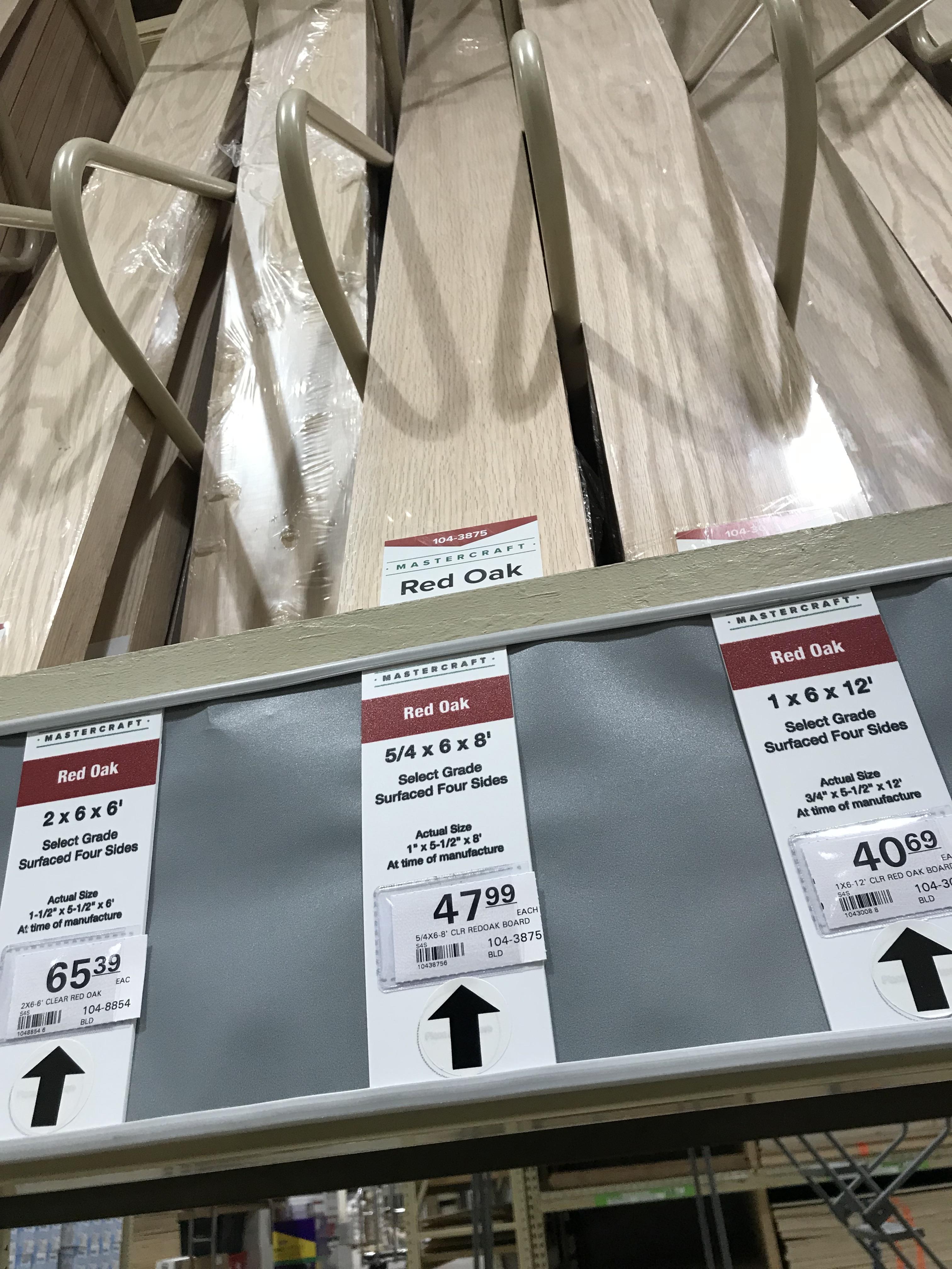
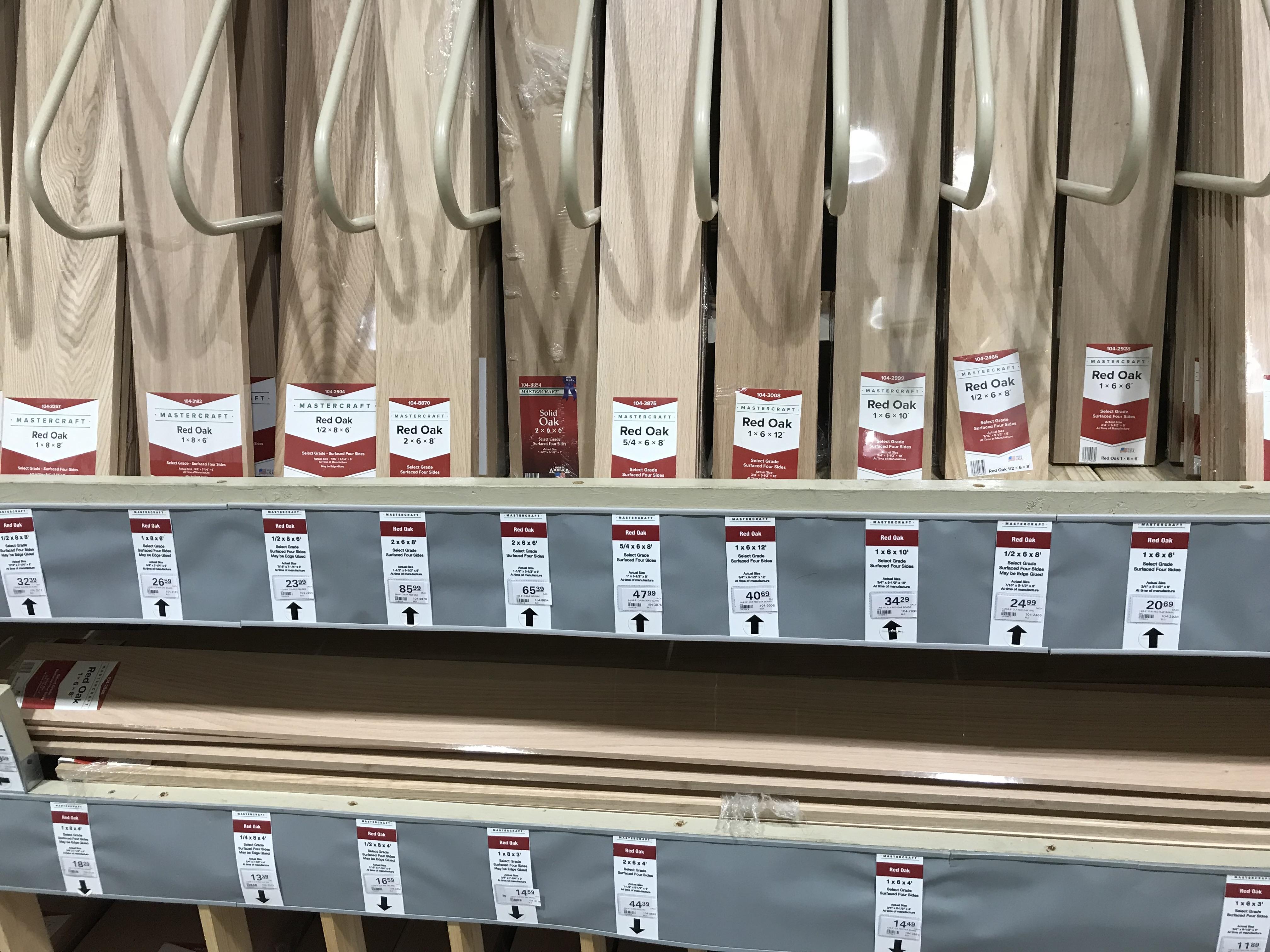

This ViceBox was designed to be built from 1" thick lumber. This thickness is essential when dealing with cavities on both sides of a board; rigidity; distances to an edge to prevent splits and for several other reasons. While most lumber at the big-box stores is nominal " (actual 3/4") many stores carry "5/4 Boards" which are actual 1" thick. This thickness is also available at sawmills that sell retail. Another option is the Oak Stair Treads like the ones I used in my first Instructable "Build a MikroBench...". Several of the prototypes were built using these treads. Ideal for the BOX but, because they are multi-board laminates, they did NOT work for Vice Boards because they tended to flex under pressure. If another source of material for the Vice Boards is available then two MikroVices can be built from one $25 Oak Stair Tread like this one, bringing the cost per down to $13 for materials. A very affordable alternative
Cutting The Boards At Menards :-)
For this demo I stopped at Menards to purchase a 5/4 x 6 x 8' Oak Board for $43. We were using my wife's small car on this trip so I could not haul an 8' board home. At Menards I took the 8' oak board back to their warehouse where they have a "self serve" miter saw. There was a ruler and a pencil there so had at it. One of the employees took the photo above. By the time I left the store all of the 21" boards were cut to length. These shorter lengths fit in the back seat of my wife's car so when I got home all I needed to do was rip two of those boards to 2 3/4" to get the SIDES and VICE BOARDS. From the cutoffs I then cut the two FEET at 3 1/2" x 3 1/2" each.
Final Board Sizes
- 1 TRAY1 @ 1" x 5 1/2" x 21"
- 2 SIDES @ 1" x 2 3/4" x 21"
- 2 FEET @ 1" x 3 1/2" x 3 1/2"
- 2 VICE BOARDS @ 1" x 2 3/4" x 7"
- 1 VICE BOARD @ 1" x 2 3/4" x 10 1/2"
- 1 VICE BOARD @ 1" x 2 3/4" x 14"
Making Dimples


This project is all about "holes", lots of them! A lot of thought, time, calculation and testing went into the location, diameter and depth for each. Boring those holes will take place in Step #4 using some carefully selected bits. All of those bits are at their best if they can start the boring in a "dimple" rather than just on a pencil mark. Dimples prevent "bit jump", a common issue when drilling especially when using Forstner bits. This Step #3 is all about "Making Dimples" .
Dimple Making Methods
There are three methods for locating and making dimples:
- Tape Measure Method
- DIY Template Method
- Purchased CNC Template Method
1: The Tape Measure Method
This would typically be the method used when only one MikroVice will be built. It requires only a few very basic measuring and marking tools and the "Hole Pattern" PDF attached:
- Clip tape measure on left end grain of each board
- Place a pencil mark at each location as dimensioned on the Hole Pattern
- Place a Square along the top edge and draw a line vertically at each mark
- Place the tape measure at top left and then a pencil mark 1 3/4" down. Repeat on right
- Use a straight edge to draw a horizontal line the full 21" of the board
- Use a Scratch Awl to make the mark at all intersections of the two lines
The boards are now full of dimples and ready for Step #4: Drilling Countersinks and Pilots
2: The DIY Template Method
If there are plans to make more then one MikroVice then it is probably worth making a template. The template starts with the same methods and tools used above however those dimples are placed on a 1/2" x 7" x 23" piece of plywood. Then a 1/4" bit is used at each of those dimples to drill holes full thru. Later in this Step I demonstrate using 1/4" Metalworker's Punch to create "Dimples" on the workpiece.
There are two methods for making your own Template. The first requires access to a Vcarve compatible CNC router. (Mine is a 4 year-old +- NextWave Piraha XL with 12" x 24" capacity). If your machine is compatible with the attached .crv or .tap files then it is a matter of placing a 1/2" x 7" x 23" piece of MDF on the CNC table, loading the .tap toolpath file and clicking "START".
Since many woodworkers, especially newbies, will not have access to a CNC the 2nd option would be to use the attached PDF Template Hole Pattern:
- Follow all of the same steps as above for making dimples on a board but then...
- Use a 1/4" Brad Point or Forstner bit to drill the 1/4" diameter "Punch Holes"
- Use a 3/8" Brad Point or Forstner to drill the 3/8" Alignment Peg Holes
The Template is now ready for use as demonstrated below
3: Purchased CNC Created Template Method
One of the main reasons I purchased a Piranha FX CNC years ago is for creating accurate templates. While my machine is not capable of running templates in any sort of volume I make extras to sell to students. If readers of this Instructable are interested in purchasing a template rather than making their own please PM me. If there are enough requests I will post to Etsy.
Using the Templates To Dimple for Drilling
The one template serves several different boards so it is important to review the attached Hole Pattern to determine which holes are dimpled for each board. For example the VICE BOARDS don't get the GRK dimples etc.
To Dimple TRAY1:
- Select what will be the top (most visible) surface of TRAY1
- Place TRAY1 on a non-skid pad on a very solid and flat surface
- Place the template over TRAY1 using the protruding 3/8" pegs for alignment
- Select which holes are to be dimpled
- Place the pointed tip of a 1/4" Metalworker's Punch in desired holes then gently tap with a hammer
- After all holes are dimpled remove the template
To Dimple SIDES:
- Select what will be the outside (most visible) surface of each SIDE
- Place the two SIDES together on a solid flat surface (see photo)
- Place the template over both SLIDES using the protruding 3/8" pegs for alignment
- Select which holes are to be dimpled
- Place the pointed tip of a 1/4" Metalworker's Punch in desired holes then gently tap with a hammer
- After all holes are dimpled remove the template
To Dimple VICE BOARDS
- The VICE BOARDS shown in the drawings are 7", 10 1/2", and 14", all increments of 3 1/2
- The Alignment Pegs in the Template are placed to hold two @ 2 3/4" x 21" so if using shorter Vice Boards it works best to create the dimples on 21" boards and then recut afterwards
- Otherwise follow same instructions for dimpling as above
The boards are now all dimpled and ready for Step #4: Drilling Counterbores, Countersinks and Pilots
Downloads
Drilling Countersinks and Pilots


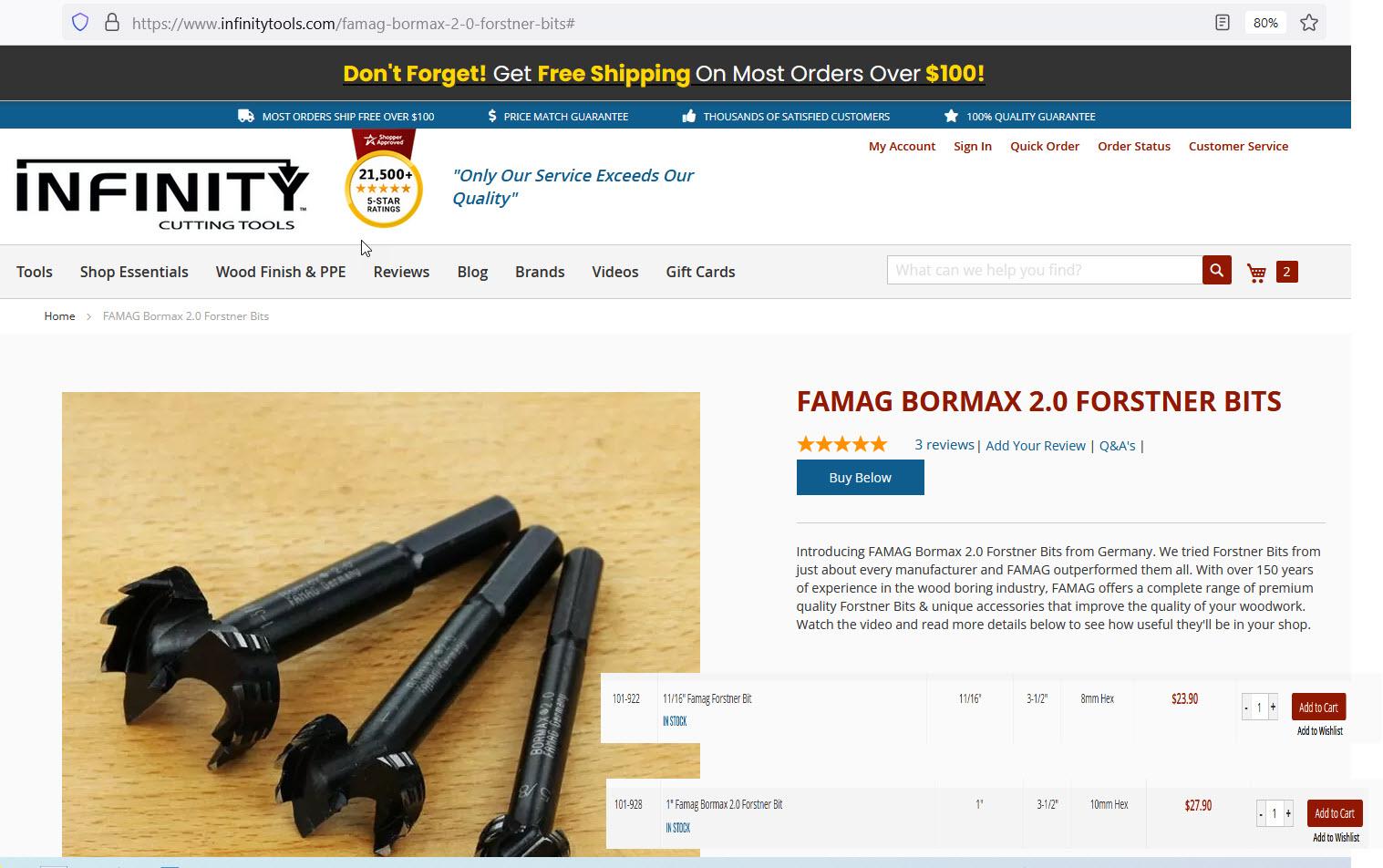




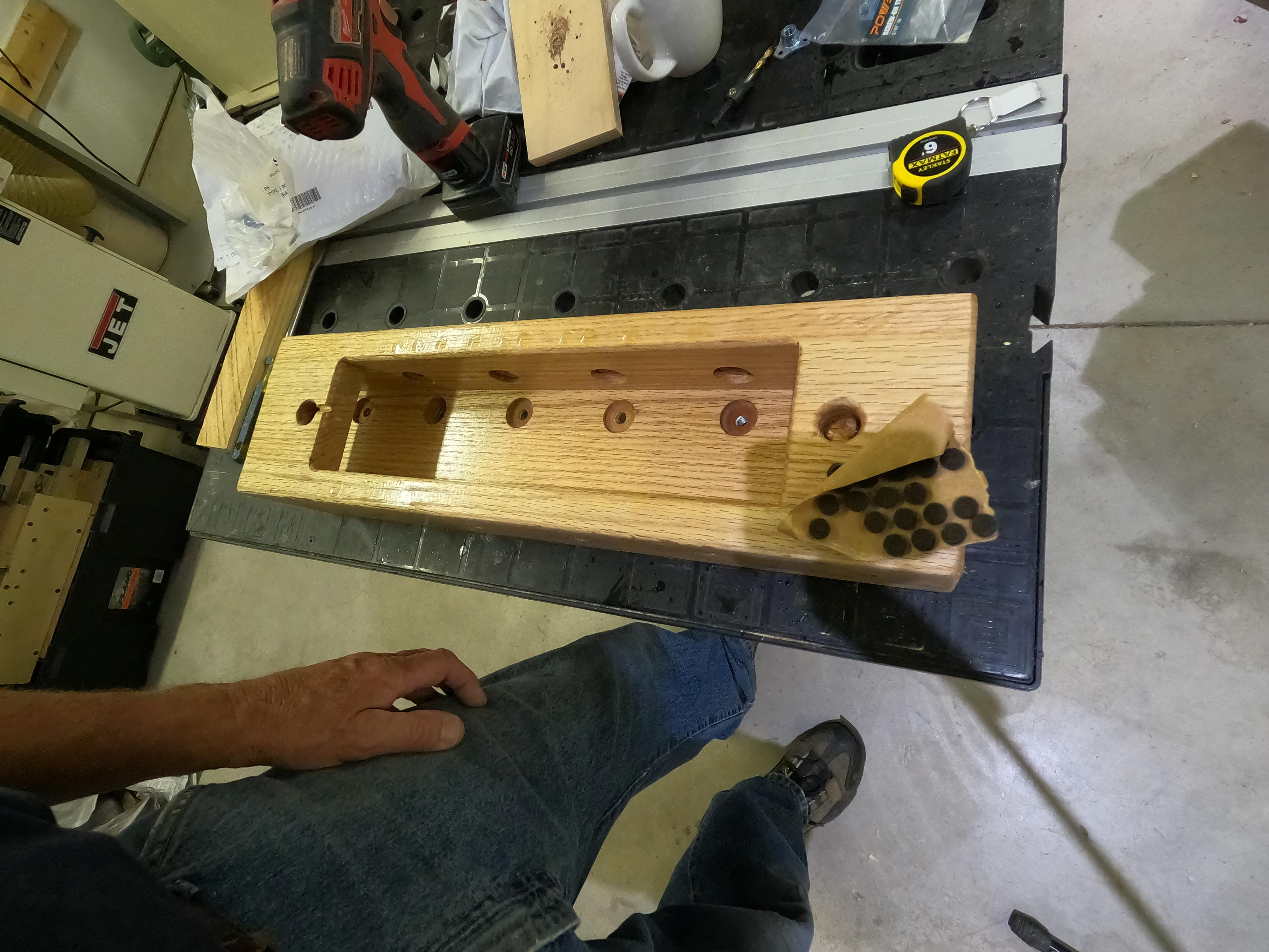
What makes a MikroVice a multi-tasking powerhouse are the integrated threaded metal "Tee Nuts "hidden" below the surface. This creates a metal-to-metal connection for the 5/16" bolts coming from the Vice Boards and, because they are permanently installed, there are no loose nuts or washers to deal with. The catch is that those Tee Nuts need to be installed from the other side of the board to counteract the amount of force applied AND they must be perfectly aligned with the long bolts and perpendicular to the surface of the board. This is a pretty tall order especially when attempting to do it with a hand-held cordless drill.
After considerable experimentation with various combinations of bits it seems as though I have dialed it in using only a 3/8" Countersink bit; a 1/2" Countersink bit and a 1 1/4" Forstner bit. (See Supplies for the bits I used). The role played by these two bits is detailed, step-by-step in the attached TRAY1 and SIDES Sequence PDF.
The Countersink and Forstner Sequence
Attached is the "Countersink and Forstner Sequence" PDF. Following this sequence with the bits (or equal) listed is critical to making this all work.
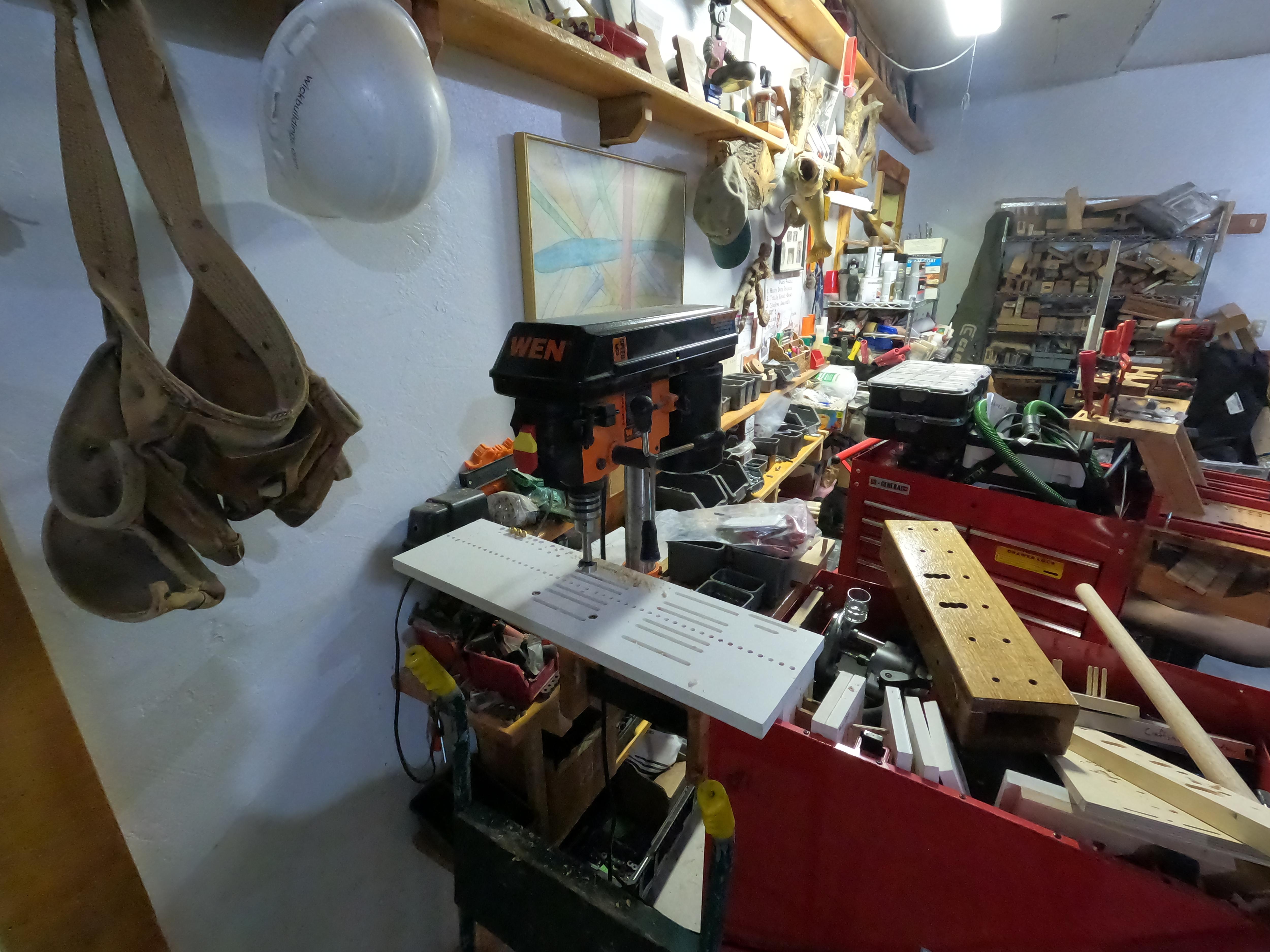
To Drillpress or Not to Drillpress?
One of the goals of this Instructable was to demonstrate how the project could be built with hand-held tools. For that reason I used a hand-held drill for all counterbores including the 1 1/4" Forstner. That said I plan to continue building more MikroVices for personal use; to demo at workshops and trade shows; and to sell. To achieve greater accuracy and a more finished appearance and to save considerable time and wear on a damaged shoulder I will be installing and calibrating most of the above countersink and Forstners bits in small, inexpensive drillpresses and then leave those set ups alone. When mounted in a drillpress the bit rarely jumps at start-up, stays straight but, more importantly, the depth Stop on the drillpress provides very accurate depth control.
All Bolt Holes, Tee Nut Counterbores and GRK Countersinks including pilots were were now complete and ready to receive hardware.
Installing Threaded Nuts




The Vices in a MikroVice have two Vice Bolts that start outside the Vice Boards then through the SIDES or TRAY1 of the BOX. Earlier prototypes used loose nuts and washers inside the BOX but this was very cumbersome trying to hold the workpiece AND the bolts AND the nuts all at the same time. I began testing all sorts of ways to install permanent threaded metal using threaded inserts, welders nuts, tee nuts and more. Eventually it came down do finding off-the-shelf hardware that would meet most of the following criteria:
- Affordability: There are 12 or more nuts used so this adds add up
- Round Counterbore: Commonly available bit size and doable with hand-held drill
- Round Wood Plug: Common diameter so possibly off-the-shelf availability
- Installation: A reasonably simple, quick method of mounting 12+ nuts
- Pull Strength: The hardware needed to match the intended use as a "vice"
- Repeatability: Metal-to-Metal is repeatable. Any other materials are not
- Aesthetics: Even underneath I wanted it to look good
All of the heavy pressure when using the vices would be outward so the hardware needed to be mounted from the inside, under the BOX.
Screw Mount Tee Nuts
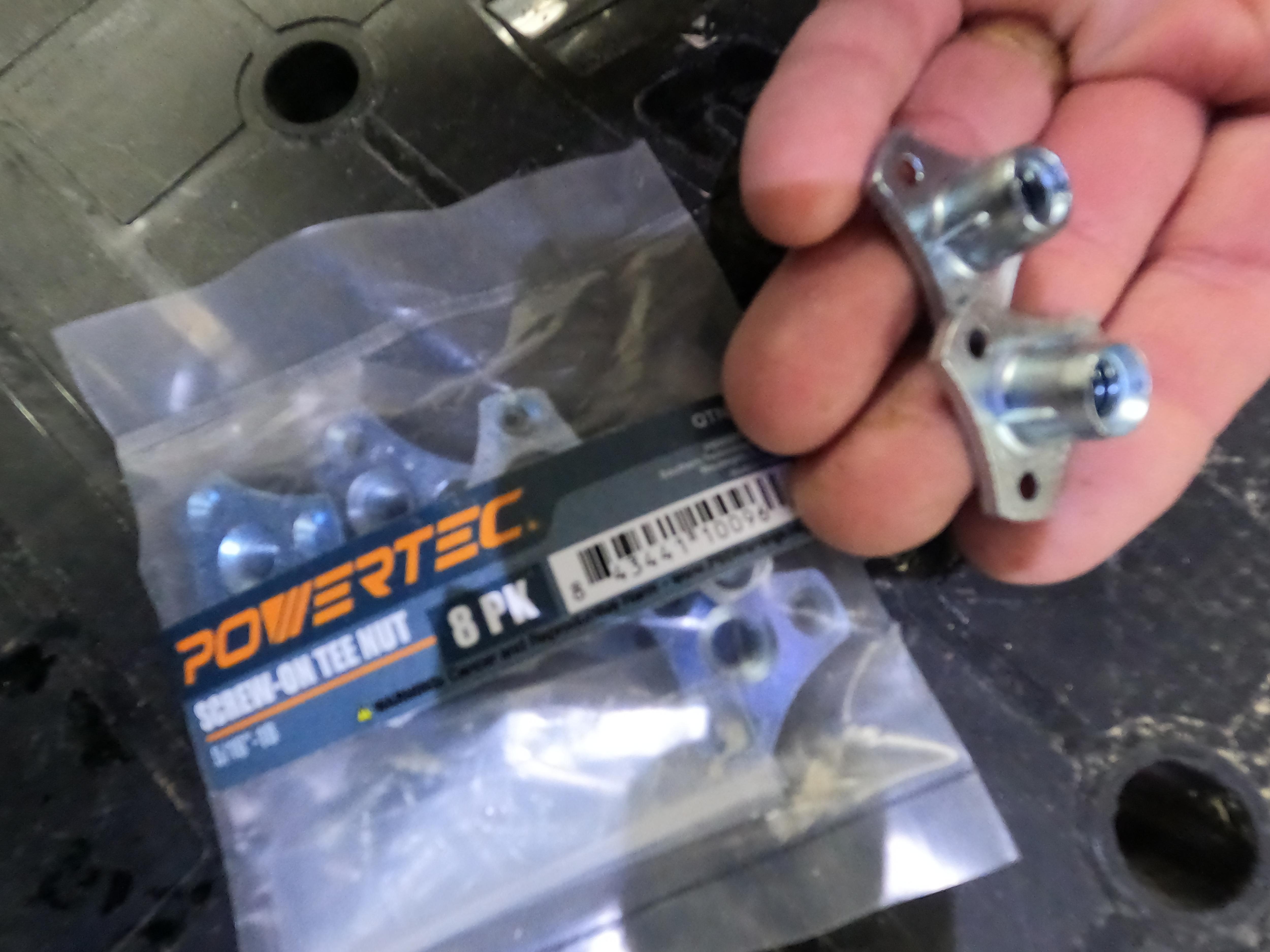
The one piece of hardware that kept coming to the surface was "Tee Nuts". Affordable, obtainable and doable but anyone having used Tee Nuts knows the issue with Tee Nuts is that the tabbed type pop out quite easily and become totally useless. The search to solve for this led to "Screw Mount Tee Nuts". Coming in at about $1.00 each they cost four times the smaller round tabbed type but well worth it:
- The thickness of the steel is about 3 times that of all other types of tee nuts meaning this will not strip under repeated and heavy use
- There are three large tabs with holes for inserting #6 wood screws
- There are several sharp tabs that stick out in the extrusion that slide into the 1/2" counterbore hole preventing any chance of twisting
- The countersink for these is a simple round 1 1/4" made with a Forstner
Although some of these come with #6 screws and intended to be mounted using those I am attempting a method that eliminates the screws using a DIY 1 1/4" hardwood plug. So far I have been unable to find a source for 1 1/4" plugs so I make my own using 1 1/4" dowel cut on a bandsaw.
How I Mount the Screw Mount Tee Nuts
Video: Mounting Screw-Mount Tee Nuts Without Screws
- Optionally add a couple drops of Epoxy Gel into 1/2" and 1 1/4" counterbores
- Place then tap a Tee Nut in the counterbore so the extrusion enters the 1/2" counterbore
- From the other side use a 5/16" bolt through the bolt hole to draw the Tee Nut tight
- Remove the 5/16" bolt from the other side
- Optionally use the #6 wood screws in the tab holes provided
- Apply wood glue in the 1 1/4" counterbore
- Insert a 1 1/4" Hardwood Plug
- Insert and tap flush to the surface a 1 1/4" Hardwood Plug
- Use a very wet rag to wipe away the oozing glue from both sides
- Allow glue time to cure
- Use a Snappy #45107 Self-Centering 7/64" Hinge Bit in the threaded Tee to pilot to other side
- Flip the board over and use a 3/8" metal-drilling-type bit in that pilot only far enough to clear hole
Once the Tee Nuts are installed the project can move on to the next Step #6: Assembly of the BOX
Assembling the BOX


Carefull consideration and much time was spent figuring out a simple, effective method for glue-up and assembly. The downside of glue is that, before it becomes an adhesive, it is just the opposite, a "lubricant". When pressure is applied hydro-static pressure is added to the mix causing the two boards to slide out of alignment.
After all sorts of trial and error it came down to a few simple steps:
- Place a non-skid rug pad on a solid flat surface
- Place the two FEET on that pad
- Stand one SIDE outside each of the FEET (3 1/2"apart)
- Place TRAY1 on top of the edges of the two SIDES (do NOT apply glue at this time)
- If a method of clamping is possible this helps hold things together better
- Starting at one corner of the top of TRAY1 send the 1/8" by 3/8" Countersink back in the same hole made earlier then redrill. This will send the 1/8" twist bit into the edge of the SIDES
- Repeat this for the remaining 5 countersinks constantly keeping all aligned
- Once all are redrilled pull TRAY1 off and the SIDES away from the FEET
- Apply glue to all edges that need to be glued including those of the FEET
- Place TRAY1 back on top then gently start installing the #9 x 2" GRKs. As this is done the GRK will find its correct path inside the pilots
- Once all 6 GRKs are done turn the BOX on one side. Use the 3/8" countersink again to pilot for the GRKs
- Insert and send home the GRKS
Immediately, when all of the above are complete, soak a rag with water and wipe off all excess glue. This will substantially reduce sanding time especially in the hard-to-reach areas underneath.
Filling the Counterbores and Nail Holes
Since the glue was already out I applied a dab of wood glue in the GRK countersinks, inserted a Hardwood plug in each then tapped with a hammer to as flush as possible. The wet rag was used again to wipe this oozing glue.
The BOX is now fully assembled and all possible glue completely wiped away. All that remains is allowing the glue to cure to continue on to Step #7 Roundovers, Sanding and Varnish
Roundovers, Sanding and Varnish


Hole Filling
It is nearly impossible to build something like this and not have at least a couple holes, joints between boards or natural cavities to fill. For decades I had used MinWax Wood Filler but that had been harder to find of late, in fact Home Depot quit carrying it altogether. Thought I'd try something new so grabbed the Dap Plastic Wood Filler. This was my first time so jury is still out but it was just a bit wetter than the MinWax so was easier to use. Will know more after varnishing to see how it takes varnish.
Roundovers
Using a roundover eliminates the sharp edges where hands will be placed to transport the MikroVice. Roundovers also prevent slivers; provide a more finished look; and reduce runs when brush varnishing. For these reasons I roundover almost all projects.
Bits Used for Roundovers
- Amana 1/4 Roundover Router Bit (to roundover BOX edges)
- Amana Miniature Roundover Bit (to roundover inside 3/8" Holes)
When to Roundover
Router bits and metal fasteners don't get along and the expensive router bit will always lose. To avoid any chance of bit-to-metal contact the roundovers could be routed before installing the GRKs and Threaded Nuts. On the other hand, applying a roundover before assembly can easily result in accidentally rounding edges that are intended to be flush to another board leaving a groove instead of a clean, flush, joint. Not the end of the world for sure and no structural issues but would not be all that appealing. Theoretically, if all of the recommended countersink and counterbore bits were used; set to the exact depths specified; and located per the dimensions shown then there "should be" enough clearance between all of the metal components and where the blades of the roundover bits will travel. Based on this "theory" and confident that all metal fasteners and hardware were out of range of the bit I routed the roundovers AFTER assembly.
Routing Insides of 3/8" Holes with a Mini-Roundover Bit
The roundover bit used for the edges has a bearing diameter of about 7/16". That bearing is too large to fit inside the 3/8" diameter of the Vice Bolt Holes. Since "aesthetics" is one of the Design Criteria I wanted the outer edges of those holes to have a roundover as well. To accomplish this I used the Amana Miniature Roundover Bit. This bit leaves a much smaller radius rounded edge and, because the bearing is so small, amplifies any imperfections it runs along, but it worked much better than trying to use a beveled countersink bit mounted in a hand-held drill.
Sanding
Sanding is my least favorite part of woodworking especially when trying to reach into tight corners. This is why a number of steps were taken earlier:
- One of the Design Criteria considerations and why the FEET are tucked inside the BOX rather than below. This recess along with limiting the height of the SIDES to 2 3/4" means the total finished height of the BOX is 3 3/4" which will just make it under the blade of a 12" Sliding Compound Miter saw. Cutting 1/32+- off the ends this way eliminates ALL sanding of the ends. They are absolutely perfect every time.
- When the Wood Washers were installed all oozing glue was immediately wiped off with a very wet rag
- The design calls for all metal hardware to be recessed at least 1/4" from any surface or edge. Since that hardware is far enough inward I felt comfortable using the jointer after the glue had set. This meant all 4 surfaces were passed over the jointer blade, even the bottom (FEET), passed over the blade. Just one or two passes cleans even the slightest bumps from the hardwood plugs and any uneven glue joints.
- Immediately after assembly, because the glue was water soluble, any oozing glue was wiped clean with a very wet rag including glue around the hardwood plugs.
Because of all the steps mentioned above only minimal sanding was needed. This sanding was done with an 18V rotary sander using 200 grit +- paper.
Varnishing
Typically I brush oil-based varnish. Oil-based finishes bring out wood tones so much better than water-based and the brush method allows for a much thicker coat than spray. It is well worth the additional wait for dry time. Because there were plans for another coat or two the brush with oil-based varnished was placed in a cup of water, a well-kept secret to keep brushes moist without smelly paint thinners.
The BOX now had several coats of varnish so ready for the next Step
Using the MikroVice




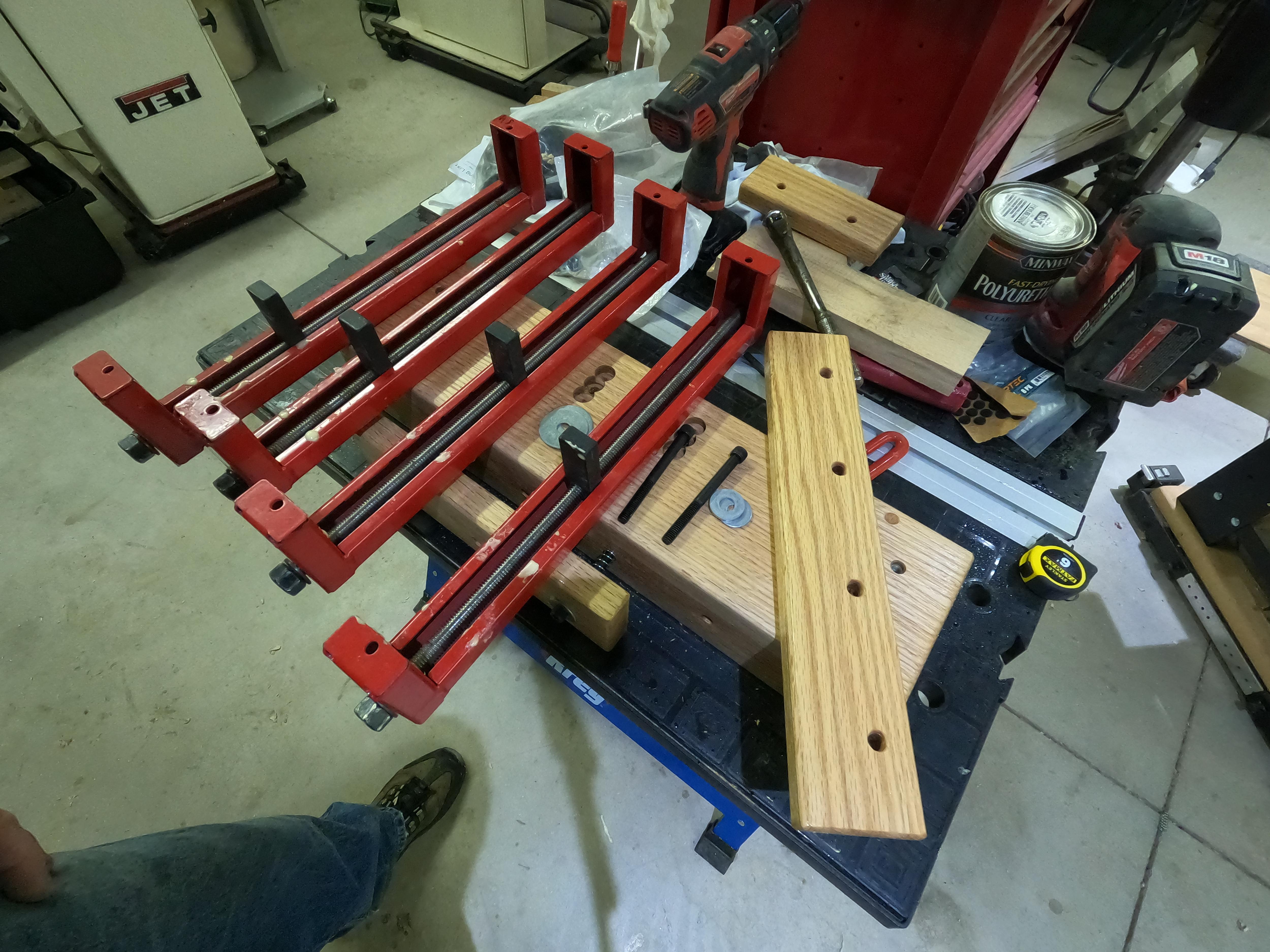
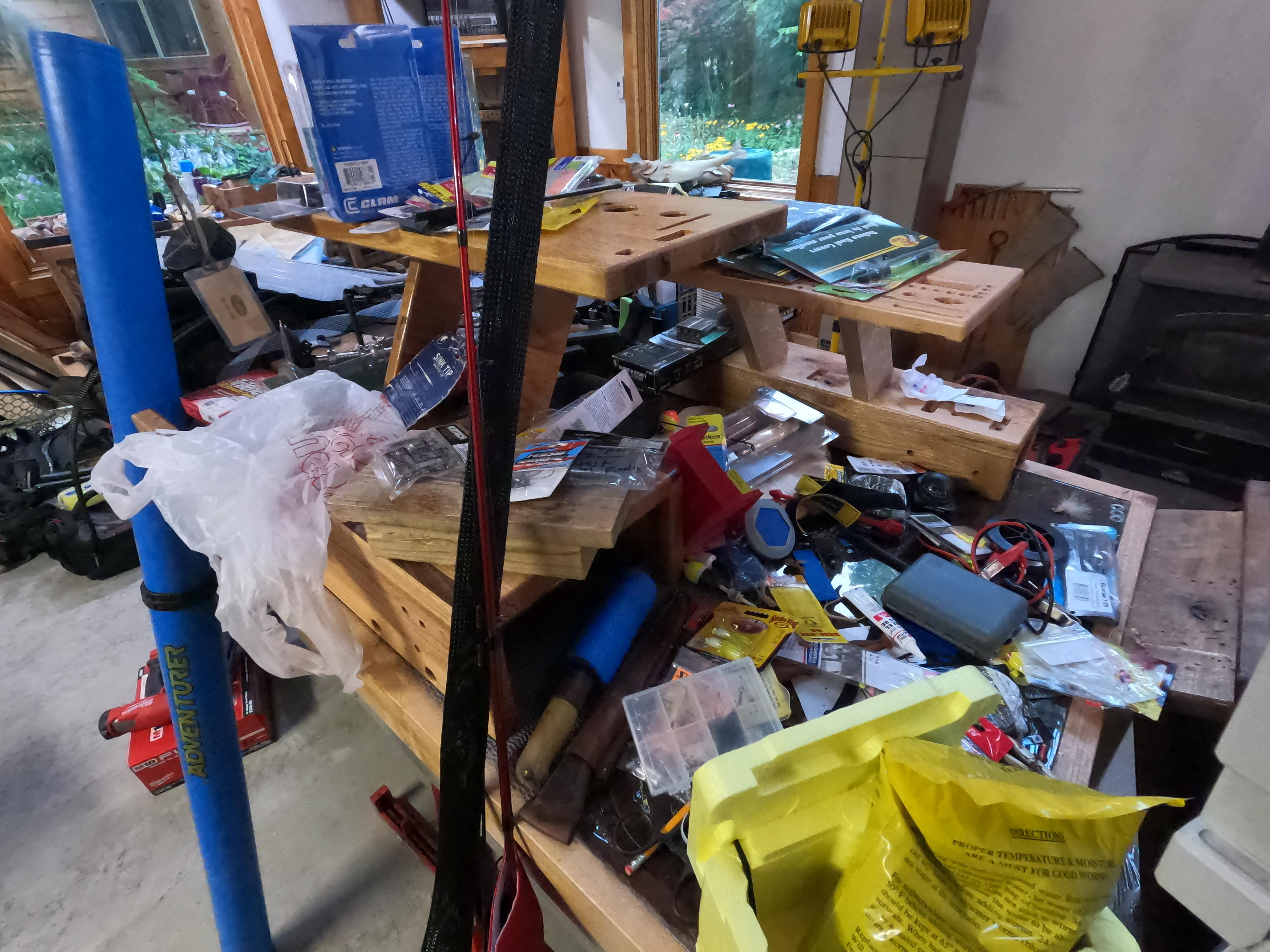


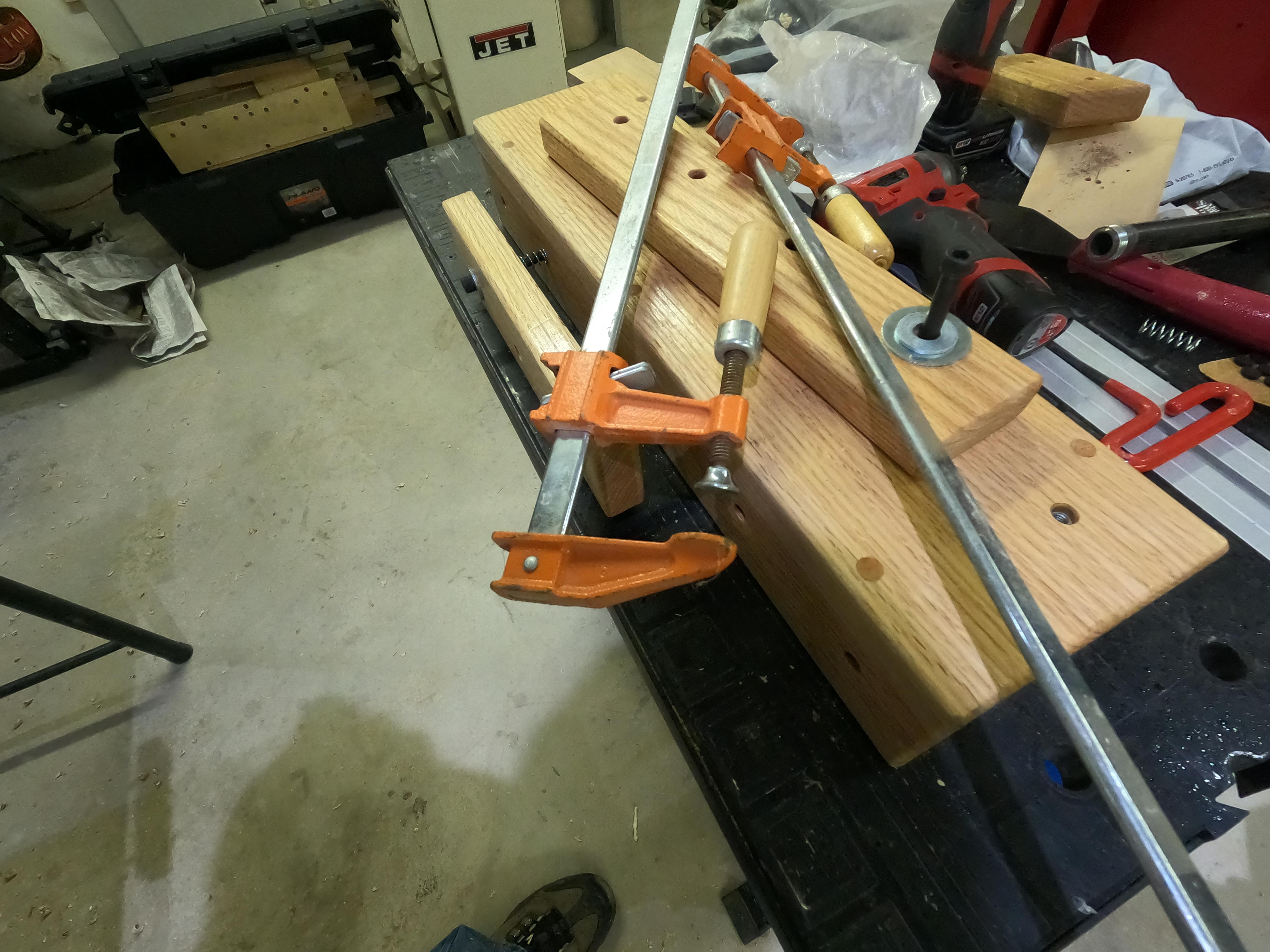


Video: Using and Mounting a MikroVice
This video is just the tip of the iceberg relative to possible uses for a MikroVice . Here I demo uses including holding materials for sanding, drilling, and hardware mounting.
- Several of my MikroVices become "dedicated" to specific tasks
- Some are set up with one or more drillpresses
- One holds a 10" Rikon Bandsaw
- One or more are always loaded with R&R Clamps
Vice Board Sizes
The hole pattern of the MikroVice is all based on 3 1/2" O.C. Making the Vice Boards in multiples of 3 1/2" was a place to start @ 7", 10 1/2" and 14". Those lengths can be modified to any desired so long as the hole pattern on the Vice Boards maintains the 3 1/2" O.C.
About the Vice Bolts
The Vices in a MikroVice are operated by 5/16" bolts. Any lesser diameter would not be enough and any larger would be overkill. There are several types of heads on a 5/16" bolt the most common being the "Hex Head", but there are other less common heads for specific applications. The bolt head I prefer and recommend for the Vice Bolts is the Socket Cap Screw Head type, These are the type that use an "Allen Wrench" rather than a hex head. An Allen Wrench will provide plenty of torque but not too much. Conventional socket or Crescent wrenches used on hex bolts allow too much torque on both the material and the MikroVice. The 5/6" Socket Cap Screw takes a 1/4" Allen.
Vice Bolt Lengths
Long bolts traditionally do not have threads for the full length of the bolt. The bolts for this MikroVice are no exception so there may be variations in bolt length depending on the thickness of the material being held by the vice. Since most of my projects us 3/4" to 2" thick would I use 3 1/2" bolts. (1" through the 1" Vice Board, 1" through the SIDE and enough space in between for up to 1 1/2" thick wood. I keep longer and shorter bolts handy for other situations.
Why the Compression Springs
The springs were not initially used during earlier prototyping. Two issues presented themselves. Both of these were solved by the compression springs:
- Without the springs the workpiece rested on the threads of the bolts. When the bolts were turned those threads scratched the workpiece. The compression spring holds the workpiece away from the threads preventing the issue.
- The holes for the 5/16" Vice Bolts are intentionally oversized to 3/8". This provides some flexibility when hole alignment or bolt angle might be a bit off. The downside is that it took two hands to hold the two Vice Boards out far enough to insert the workpiece. Since the other hand (or two on larger work-pieces) were already busy this was not acceptable. The compression bolts hold the Vice Boards out about 1 1/2' making it easy to insert the workpiece.
Locating the Vice Boards
The Vice Boards can be mounted out the front, out the back, on top or any combination of same. When building a MikroVice I usually install a Tee Nut in all available holes so the MikroVice can be used in any configuration. That said this will be a personal preference based on potential uses, cost and time. If Tee Nuts are not installed prior to assembly they can be later, after assembly, its just a bit more difficult.