Build Your Own Underwater Robot V2
by Ranuga in Circuits > Robots
27118 Views, 231 Favorites, 0 Comments
Build Your Own Underwater Robot V2


)
Hello everyone, I'm Ranuga, a 16-year-old 11th-grade student, and I'm back here on Instructables with another exciting project. I'm thrilled to share with you the journey of building my second ROV, which I call ROV V2, or ROV2 for short. This project builds upon the foundations formed by my first ROV V1. If you haven't seen my first project, I suggest you check it out here to understand the evolution of my underwater exploration.
This ROV2 is integrated with a Raspberry Pi, allowing it to be converted into a fully autonomous or semi-autonomous underwater robot (AUV). This upgrade opens up a world of possibilities for automated underwater exploration.
The use of brushless motors makes this project easier, as they can be used right out of the box without the need for waterproofing. This simplifies the build process and ensures reliable performance.ROV2 features a vector thrust configuration, which enables it to move in any direction. This agility is key for smoothly navigating complex underwater environments.
ROV2 is equipped with a 720P wide-angle live camera feed, providing clear and expansive underwater visuals. It is also capable of functioning depth and orientation hold, enhancing stability and control during operations. Additionally, the use of a lithium polymer battery allows ROV2 to dive underwater for 30-45 minutes, giving ample time for exploration.
I hope you find this tutorial helpful and inspiring for your underwater projects. Let's dive into the details and start building!
Supplies
Electronics:
- 30A ESCs × 6
- A2212/13T 1000KV Brushless Outrunner Motors × 6
- Arduino MEGA × 1
- Arduino UNO × 1
- 3S 3300 mAh LIPO Battery × 1
- MS5540 Pressure Sensor × 1
- HSCDTD008A 3-Axis Compass Magnetometer Module × 1
- 720P FPV Camera × 1
- RGB LED Module × 1
- Voltage Measuring Module × 1
- Two-Way Relay × 2
- 18650 Battery × 3
- 3S 18650 BMS × 1
- FLYSKY FS-i6X with FS-iA10B Receiver × 1
- Toggle Switch × 1
- 60m Twin Pair Wires
Hardware Supplies:
- 3mm White Acrylic Sheets
- V-Slot 2020 Aluminium Extrusions (2m)
- M4 Hex Screws
- M3 Screws
- 20mm PVC Pipe (900mm length)
- 90mm End Caps × 4
- PLA Filament
- 90mm PVC Pipe (450mm length)
- 90mm Threaded End Caps × 2
- 60mm Diameter Clear Circular Acrylic Piece × 1
- Hexagonal M3 10mm Male-Female Copper Spacers × 21
- Weights
- Epoxy Glue
- Silicon Glue
Tools:
- 3D Printer
- Drill
- Laser Cutter
Structure


ROV2 uses a custom-designed rigid frame, which is essential for any underwater robot to ensure manoeuvrability. The hydrodynamic structure allows it to perform exceptionally well underwater. The frame is primarily composed of acrylic sheets and aluminium extrusions.
1. Prepare Materials:
- 3mm white acrylic sheets
- V slot 2020 aluminium extrusions (350mm length)
- M4 hex screws
- Laser cutter
- 3D printer
- Small piece of rubber
- M3 screws
2. Laser Cut Acrylic Sheets:
- For the side panels, use 3mm white acrylic sheets. Laser-cut two panels according to the design. Download the CAD files below.
3. Assemble the Frame:
- Connect the two laser-cut acrylic side panels using three V-slot 2020 aluminium extrusions, each 350mm in length.
- Secure the aluminium extrusions to the acrylic panels using M4 hex screws to create a sturdy and reliable structure.
4. Mount the Thrusters:
- Six thrusters are mounted on the side panels of ROV2:
- Two thrusters are mounted vertically to control diving and surfacing, effectively managing the depth of the robot.
- Four thrusters are mounted at a 45-degree angle to create a vector thrust configuration, allowing the ROV to move in any direction.
- 3D print brackets for mounting the horizontal thrusters at a 45-degree angle.
- Attach the brackets to the side panels using M3 screws, placing a small piece of rubber between the bracket and the panel to reduce vibration.
- Install the thrusters as described.
Each component and step is essential for ensuring ROV2 performs effectively and reliably underwater. Download the CAD files for all components below and follow the detailed assembly instructions to complete your ROV2 structure.
Thrusters and ESCs


.png)

For ROV2, I used 3D-printed, modified BlueRobotics T100 thrusters, which are a cost-effective choice. These thrusters use $5 A2212/13T 1000KV Brushless Outrunner Motors. Since these motors have no contact with the inner coil, they can be used underwater without causing any damage. However, it's important to dry the motors after using them in fresh water. If they've been used in salty water, you need to rinse them with fresh water and then dry them thoroughly. This maintenance ensures the longevity and performance of the thrusters. Each thruster provides approximately 1.26kg of thrust at 12V, 10A.
However, the electronic speed controllers (ESCs) need to be waterproofed as they are not designed for underwater use. I have 3D printed a case to house the ESCs and waterproofed it with epoxy resin. Each thruster requires a separate ESC.
Currently, I'm using reverse thrust only for the vertical thrusters. To reverse the thrust direction, you simply swap any two wires coming from the ESC. There are bidirectional ESCs available on the market but I have used a normal ESC and a relay to swap the two connections.
To mount the horizontal thrusters at a 45-degree angle, I have 3D printed a bracket. This bracket can be easily mounted onto the side panels using M3 screws. I've also placed a small piece of rubber between the bracket and the side panel to reduce vibrations made from the thruster.
All the CAD files for these components are available for download below.
1. Prepare the 3D-printed Cases:
- 3D print the cases for the ESCs according to the provided design. Ensure that the cases are appropriately sized to fit the ESCs snugly.
2. Insert the ESCs:
- Place each ESC inside its respective 3D-printed case. Make sure that the ESC fits securely within the case.
3. Seal the Cases:
- Apply a thin layer of epoxy resin inside the case where the ESC will sit. This layer helps create a waterproof seal.
- Place the ESC in the case, ensuring it is centred and does not obstruct the case’s sealing surface.
4. Allow Curing:
- Let the epoxy resin cure fully according to the manufacturer’s instructions. This usually takes several hours to overnight.
5. Test the Seal:
- After curing, inspect the case to ensure that all edges are properly sealed and that there are no gaps or leaks.
Electronics


When it comes to electronics, it’s one of the most crucial aspects of an ROV. It handles all the decisions and operations of the robot. For ROV2, I’m using an Arduino Mega as the brain of the robot. The Arduino Mega is easy to program using the Arduino IDE, which simplifies the development process. Additionally, I’ve incorporated various actuators and indicators to enhance the capabilities of the ROV and make it more advanced.
Electronics Tray
For easy access and assembly of electronic parts, I have 3D-printed an electronic tray that fits inside the enclosure. This tray simplifies the process of inserting and organizing the electronic components. You can download the CAD files for the tray below.
Components
Here’s a list of the components used in ROV2, along with their purposes:
- MS5540 Pressure Sensor: Reads water pressure to calculate depth and monitor temperature.
- HSCDTD008A 3-Axis Compass Magnetometer Module: Provides orientation data to assist with navigation and maintain heading.
- 720P Camera Module: Delivers a wide-angle live feed for clear underwater visuals and exploration.
- RGB LED Module: Acts as an indicator to show the status of various systems, such as power, connectivity, and operational modes.
- TTL to RS485 Module: Ensures long-range wired communication.
- Arduino Mega: Serves as the brain of the ROV, handling all decision-making and control.
- Voltage Measuring Module: Monitors the voltage of the batteries to ensure they are within safe operating limits.
- Two-Way Relay: Swaps the connections to reverse the direction of the vertical thrusters, allowing for precise control over diving and surfacing.
Electronic Enclosure
.png)


The electronic enclosure is essential for safeguarding and housing the ROV's electronic components. Here, I’m using a 90mm diameter, 450mm long PVC tube to create a durable and waterproof enclosure. This design features threaded end caps that provide easy access to the electronics for maintenance and adjustments. The front end cap includes a clear acrylic window for the camera, while the back end-cap is equipped with multiple wire outlets and additional sealing to prevent water ingress. This ensures that all electronic components remain secure and operational during underwater exploration. To get a clearer idea of the assembly process and design, refer to the above images.
1. Prepare the Enclosure:
- Cut the PVC tube to the required length (450mm).
2. Front End Cap:
- Cut a 60mm diameter hole in the front end cap.
- Cut a 70mm diameter circle from clear acrylic and glue it to the inner side of the front end cap to create a window for the camera.
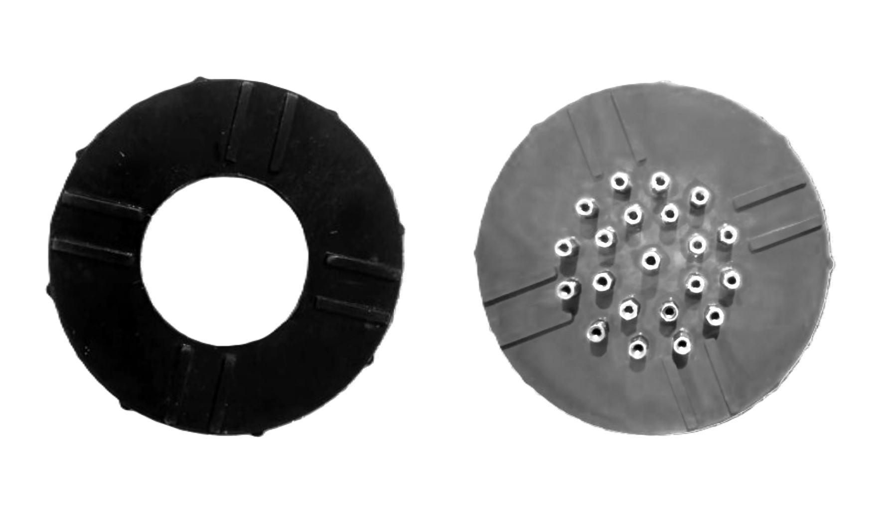
3. Back End Cap:
- Drill 21 holes of 3mm diameter in the back end cap for the wires.
- Insert and secure 21 hexagonal M3 10mm male-female copper spacers through the holes from both sides to prevent water leaks.
- Apply a layer of epoxy around the outer side of the back end cap to further seal against water ingress.
4. Final Checks:
- Ensure all components are securely installed and sealed before testing the enclosure.
Ground Controller

To control the ROV, I'm currently using a standard Flysky i6x transmitter. This transmitter offers 10 channels, allowing for a variety of functions to be controlled. However, one limitation is that the throttle stick doesn't come with a self-centering feature. This feature is particularly useful because it helps stabilize the ROV at a desired depth by automatically returning the throttle to the neutral position when released.
To address this, you have two options: you can either purchase a self-centering joystick separately or modify the existing throttle stick. I opted for the latter by hacking it with some 3D-printed parts and a spring. This modification ensures that the throttle stick returns to the centre, making it easier to control the ROV. Unlike aerial drones, ROV thrusters can rotate in both clockwise (CW) and counterclockwise (CCW) directions, so the middle position on the throttle corresponds to a stop.
The receiver, which is part of the Flysky system, is connected to an Arduino on the surface. This Arduino reads the signals sent from the transmitter and transmits them to the ROV through the tether. This setup allows for precise and responsive control of the ROV's movements and functions.
I've also 3D printed a phone mount for the Flysky transmitter. The FPV feed from the ROV can be viewed on the phone using an OTG converter, making it easy to see what's happening underwater in real-time.
#include <Servo.h>


const int channel1Pin = 2; // Receiver channel 1 pin (throttle)
const int channel2Pin = 3; // Receiver channel 2 pin (yaw)
const int channel3Pin = 4; // Receiver channel 3 pin (pitch)
const int channel4Pin = 5; // Receiver channel 4 pin (roll)
const int channel5Pin = 6; // Receiver channel 5 pin (depth hold switch)
const int channel6Pin = 7; // Receiver channel 6 pin (orientation hold)


void setup() {
  Serial.begin(9600); // Initialize serial communication
  pinMode(channel1Pin, INPUT);
  pinMode(channel2Pin, INPUT);
  pinMode(channel3Pin, INPUT);
  pinMode(channel4Pin, INPUT);
  pinMode(channel5Pin, INPUT);
  pinMode(channel6Pin, INPUT);
}


void loop() {
  int channel1Value = pulseIn(channel1Pin, HIGH); // Read PWM value from channel 1
  int channel2Value = pulseIn(channel2Pin, HIGH); // Read PWM value from channel 2
  int channel3Value = pulseIn(channel3Pin, HIGH); // Read PWM value from channel 3
  int channel4Value = pulseIn(channel4Pin, HIGH); // Read PWM value from channel 4
  int channel5Value = pulseIn(channel5Pin, HIGH); // Read PWM value from channel 5 (depth hold switch)
  int channel6Value = pulseIn(channel6Pin, HIGH); // Read PWM value from channel 6 (orientation hold)


  // Send data via serial
  Serial.print(channel1Value);
  Serial.print(",");
  Serial.print(channel2Value);
  Serial.print(",");
  Serial.print(channel3Value);
  Serial.print(",");
  Serial.print(",");
  Serial.print(channel4Value);
  Serial.print(",");
  Serial.print(channel5Value);
  Serial.print(",");
  Serial.println(channel6Value);


  delay(50); // Adjust the delay as needed
}
Channel Assignments:
- Throttle (Channel 1): Pin D2
- Yaw (Channel 2): Pin D3
- Pitch (Channel 3): Pin D4
- Roll (Channel 4): Pin D5
- Depth Hold Switch (Channel 5): Pin D6
- Orientation Hold (Channel 6): Pin D7
This code reads the PWM signals from the Flysky receiver channels and sends the values over serial communication. The data can then be received by the ROV's onboard microcontroller to control the ROV.
Tether


Creating a reliable tether for your ROV is crucial for maintaining effective communication and power transfer between the surface and your underwater vehicle. In this section, I’ll guide you through the process of constructing a 30-meter tether using twin-pair wire.
1. Twin-Pair Wire:
- Start with a 60-meter twin-pair wire and cut it into two equal 30-meter lengths.
2. Wire Configuration:
- Use one pair of wires for TX (Transmit) and RX (Receive) communication.
- Use the other pair of wires for the camera signal and Ground.
3. Securing the Wires:
- To keep the wires organized, use a 10mm heat-shrink tube.
- Cut small 20mm sections from the heat-shrink tube.
- Slide these sections onto the four wires to bundle them neatly.
4. Neat and Efficient Tether:
- Ensure the heat-shrink tube sections are properly placed to create a well-organized and reliable 30-meter tether.
Note - Extending Communication Distance:
The method described is suitable for communication up to 40 meters. For longer distances, such as 100 meters or more, you could use a TTL to RS-485 module to extend communication up to 1200 meters (1.2 km). However, for ROV V2, I am not using RS-485; the tether configuration remains the same as in V1.
Pressure Sensor


For the ROV2 project, ensuring reliable depth measurements requires using the MS5540C pressure sensor. However, this sensor is not inherently water-resistant, so we need to make it waterproof to operate in underwater environments.
To achieve this, I designed a custom 3D-printed case specifically for the MS5540C sensor. The case is crafted to perfectly fit the sensor, providing a snug enclosure that minimizes the risk of water ingress. The design includes features that facilitate easy placement of the sensor and secure attachment points.
Once the case is printed, the sensor is carefully inserted into the designated compartment. It is important to ensure that the white cylindrical part of the sensor, which is very sensitive and can be easily damaged, is not touched during this process. This part must remain open to water, as it is crucial for accurate pressure readings.
To create a watertight seal, we use silicone sealant, applying it generously around all openings and joints. The silicone not only secures the sensor in place but also prevents any water from reaching the electronic components. This process requires attention to detail to ensure complete coverage and avoid air bubbles that could compromise the seal.
Downloads
Circuit Diagram and Code

One of the most challenging aspects of building an ROV is designing the circuits and writing the code. The complete circuit diagram for the ROV onboard controller, including all components, is provided above. As mentioned earlier, this ROV is capable of performing advanced functions such as depth and orientation hold. The code for these features is provided separately for clarity. Please note that the ground controller's TXD and RXD must be crossed and connected to the ROV's controller. Specifically, the RXD from the ground controller should be connected to the TXD of the ROV controller, and vice versa for the TXD and RXD.
Depth Hold Code
#include <Wire.h>
#include <ms5540c.h> // Include your MS5540C library


// Define your pressure sensor and thrusters
ms5540c pressureSensor;
const int csPin = 12; // Updated pin number for CS
const int upThrusterPin1 = 8;
const int upThrusterPin2 = 9;
const float depthHoldTarget = 5.0; // Target depth in meters


// PID control parameters
const float kp = 0.5; // Proportional gain
const int minThrusterPower = 1000; // Minimum thruster power (PWM value)
const int maxThrusterPower = 2000; // Maximum thruster power (PWM value)


void setup() {
  Serial.begin(9600); // Initialize serial communication
  Wire.begin(); // Initialize I2C communication
  pinMode(csPin, OUTPUT);
  digitalWrite(csPin, HIGH); // Disable sensor initially
  digitalWrite(csPin, LOW);  // Select sensor
  pressureSensor.begin();    // Initialize the sensor
  digitalWrite(csPin, HIGH); // Deselect sensor


  pinMode(upThrusterPin1, OUTPUT); // Set thruster pins as outputs
  pinMode(upThrusterPin2, OUTPUT);
}


void loop() {
  // Read current depth from the pressure sensor
  digitalWrite(csPin, LOW);  // Select sensor
  float currentDepth = getPressureInMeters(); // Get the current depth from the sensor
  digitalWrite(csPin, HIGH); // Deselect sensor

  // Calculate error
  float depthError = depthHoldTarget - currentDepth;

  // Calculate thruster power based on the error
  int thrusterPower = constrain(depthError * kp, minThrusterPower, maxThrusterPower);


  // Apply control to thrusters based on depth error
  if (depthError > 0) {
    // Need to go up
    analogWrite(upThrusterPin1, thrusterPower);
    analogWrite(upThrusterPin2, thrusterPower);
  } else {
    // Need to go down or maintain depth
    analogWrite(upThrusterPin1, minThrusterPower);
    analogWrite(upThrusterPin2, minThrusterPower);
  }

  // Print data for debugging
  Serial.print("Current Depth: ");
  Serial.print(currentDepth);
  Serial.print(" meters, ");
  Serial.print("Thruster Power: ");
  Serial.println(thrusterPower);


  delay(500); // Adjust the delay as needed for stability
}


// Function to get pressure in meters
float getPressureInMeters() {
  float pressure = pressureSensor.getPressure(); // Read pressure from the sensor
  return pressure / 9.81; // Convert pressure to depth in meters (1 Pascal = 1 kg/(m·s²), gravity = 9.81 m/s²)
}
Orientation Hold Code
#include <Wire.h>
#include <HMC5883L.h> // Include your HMC5883L library


// Define compass and ESC pins
HMC5883L compass;
const int escFrontLeft = 9;  // ESC pins connected to PWM outputs
const int escFrontRight = 10;
const int escBackLeft = 11;
const int escBackRight = 12;
const float targetHeading = 0.0; // Target heading in degrees


// PID control parameters
const float kp = 1.0; // Proportional gain
const int minESCValue = 1000; // Minimum ESC power (PWM value)
const int maxESCValue = 2000; // Maximum ESC power (PWM value)


void setup() {
  Serial.begin(9600); // Initialize serial communication
  Wire.begin(); // Initialize I2C communication


  // Initialize the compass sensor
  compass = HMC5883L(); // Create an instance of the HMC5883L class

  // Check if the sensor is connected correctly
  if (!compass.begin()) {
    Serial.println("HMC5883L not connected.");
    while (1); // Halt if not connected
  }


  // Initialize ESC pins
  pinMode(escFrontLeft, OUTPUT);
  pinMode(escFrontRight, OUTPUT);
  pinMode(escBackLeft, OUTPUT);
  pinMode(escBackRight, OUTPUT);


  // Ensure all ESCs are stopped initially
  analogWrite(escFrontLeft, minESCValue);
  analogWrite(escFrontRight, minESCValue);
  analogWrite(escBackLeft, minESCValue);
  analogWrite(escBackRight, minESCValue);
}


void loop() {
  // Read current heading from the compass
  Vector raw = compass.readRaw(); // Replace with the correct method from your library
  float currentHeading = atan2(raw.YAxis, raw.XAxis) * 180 / PI; // Convert to degrees

  // Normalize heading to 0-360 degrees
  if (currentHeading < 0) {
    currentHeading += 360;
  }


  // Calculate error
  float headingError = targetHeading - currentHeading;

  // PID Controller (Basic Example)
  int escPower = constrain(headingError * kp, minESCValue, maxESCValue);


  // Apply control to ESCs based on heading error
  // Example: Adjust ESCs to correct orientation
  if (headingError > 0) {
    // Turn right
    analogWrite(escFrontLeft, escPower);
    analogWrite(escFrontRight, minESCValue);
    analogWrite(escBackLeft, escPower);
    analogWrite(escBackRight, minESCValue);
  } else {
    // Turn left
    analogWrite(escFrontLeft, minESCValue);
    analogWrite(escFrontRight, escPower);
    analogWrite(escBackLeft, minESCValue);
    analogWrite(escBackRight, escPower);
  }


  // Print data for debugging
  Serial.print("Current Heading: ");
  Serial.print(currentHeading);
  Serial.print(" degrees, ");
  Serial.print("ESC Power: ");
  Serial.println(escPower);


  delay(500); // Adjust the delay as needed for stability
}
ROV2 Code
#include <Wire.h>
#include <HMC5883L.h> // Include your HMC5883L library
#include <ms5540c.h> // Include your MS5540C library


// Define compass, pressure sensor, and ESC pins
HMC5883L compass;
ms5540c pressureSensor;
const int csPin = 12; // Updated pin number for CS
const int escFrontLeft = 9;  // ESC pins connected to PWM outputs
const int escFrontRight = 10;
const int escBackLeft = 11;
const int escBackRight = 8;
const int upThrusterPin1 = 23;
const int upThrusterPin2 = 22;
const float targetHeading = 0.0; // Target heading in degrees
const float depthHoldTarget = 5.0; // Target depth in meters


// PID control parameters
const float kpHeading = 1.0; // Proportional gain for heading control
const float kpDepth = 0.5; // Proportional gain for depth control
const int minESCValue = 1000; // Minimum ESC power (PWM value)
const int maxESCValue = 2000; // Maximum ESC power (PWM value)
const int minThrusterPower = 1000; // Minimum thruster power (PWM value)
const int maxThrusterPower = 2000; // Maximum thruster power (PWM value)


void setup() {
  Serial.begin(9600); // Initialize serial communication
  Wire.begin(); // Initialize I2C communication


  // Initialize the compass sensor
  compass = HMC5883L(); // Create an instance of the HMC5883L class
  if (!compass.begin()) {
    Serial.println("HMC5883L not connected.");
    while (1); // Halt if not connected
  }


  // Initialize the pressure sensor
  pinMode(csPin, OUTPUT);
  digitalWrite(csPin, HIGH); // Disable sensor initially
  digitalWrite(csPin, LOW);  // Select sensor
  pressureSensor.begin();    // Initialize the sensor
  digitalWrite(csPin, HIGH); // Deselect sensor


  // Initialize ESC and thruster pins
  pinMode(escFrontLeft, OUTPUT);
  pinMode(escFrontRight, OUTPUT);
  pinMode(escBackLeft, OUTPUT);
  pinMode(escBackRight, OUTPUT);
  pinMode(upThrusterPin1, OUTPUT);
  pinMode(upThrusterPin2, OUTPUT);


  // Ensure all ESCs and thrusters are stopped initially
  analogWrite(escFrontLeft, minESCValue);
  analogWrite(escFrontRight, minESCValue);
  analogWrite(escBackLeft, minESCValue);
  analogWrite(escBackRight, minESCValue);
  analogWrite(upThrusterPin1, minThrusterPower);
  analogWrite(upThrusterPin2, minThrusterPower);
}


void loop() {
  // Read current heading from the compass
  Vector raw = compass.readRaw(); // Replace with the correct method from your library
  float currentHeading = atan2(raw.YAxis, raw.XAxis) * 180 / PI; // Convert to degrees


  // Normalize heading to 0-360 degrees
  if (currentHeading < 0) {
    currentHeading += 360;
  }


  // Calculate heading error
  float headingError = targetHeading - currentHeading;

  // PID Controller for heading
  int escPower = constrain(headingError * kpHeading, minESCValue, maxESCValue);


  // Read current depth from the pressure sensor
  digitalWrite(csPin, LOW);  // Select sensor
  float currentDepth = getPressureInMeters(); // Get the current depth from the sensor
  digitalWrite(csPin, HIGH); // Deselect sensor


  // Calculate depth error
  float depthError = depthHoldTarget - currentDepth;

  // PID Controller for depth
  int thrusterPower = constrain(depthError * kpDepth, minThrusterPower, maxThrusterPower);


  // Apply control to ESCs based on heading error
  if (headingError > 0) {
    // Turn right
    analogWrite(escFrontLeft, escPower);
    analogWrite(escFrontRight, minESCValue);
    analogWrite(escBackLeft, escPower);
    analogWrite(escBackRight, minESCValue);
  } else {
    // Turn left
    analogWrite(escFrontLeft, minESCValue);
    analogWrite(escFrontRight, escPower);
    analogWrite(escBackLeft, minESCValue);
    analogWrite(escBackRight, escPower);
  }


  // Apply control to thrusters based on depth error
  if (depthError > 0) {
    // Need to go up
    analogWrite(upThrusterPin1, thrusterPower);
    analogWrite(upThrusterPin2, thrusterPower);
  } else {
    // Need to go down or maintain depth
    analogWrite(upThrusterPin1, minThrusterPower);
    analogWrite(upThrusterPin2, minThrusterPower);
  }


  // Print data for debugging
  Serial.print("Current Heading: ");
  Serial.print(currentHeading);
  Serial.print(" degrees, ");
  Serial.print("Current Depth: ");
  Serial.print(currentDepth);
  Serial.print(" meters, ");
  Serial.print("ESC Power: ");
  Serial.print(escPower);
  Serial.print(", Thruster Power: ");
  Serial.println(thrusterPower);


  delay(500); // Adjust the delay as needed for stability
}


// Function to get pressure in meters
float getPressureInMeters() {
  float pressure = pressureSensor.getPressure(); // Read pressure from the sensor
  return pressure / 9.81; // Convert pressure to depth in meters (1 Pascal = 1 kg/(m·s²), gravity = 9.81 m/s²)
}
Feel free to adjust the code or circuit diagram as needed for your specific requirements.
KILL Switch


As mentioned earlier, I'm planning to upgrade this ROV into an autonomous underwater vehicle (AUV). AUVs are designed to operate independently without direct human control, which is why having an emergency stop mechanism is vital. An emergency stop switch, also known as a kill switch, becomes crucial in preventing potential damage or hazardous situations if the system encounters any malfunction or unexpected behaviour. This feature provides a reliable fail-safe option to immediately halt all operations, ensuring safety and preserving the integrity of the equipment.
To achieve this, I’ve designed a waterproof switch that allows you to stop the vehicle at any time. This kill switch design is specifically tailored to be easy to access and activate, even in underwater conditions. The switch assembly consists of a toggle switch housed in a waterproof casing, ensuring it remains functional and reliable in wet environments. Below are the steps to create and install the kill switch for your ROV.
- Download the CAD file for the waterproof switch case (file provided below).
- 3D print the components: the lower case and the upper case.
- Place a toggle switch in the designated position within the lower printed case.
- Apply epoxy around the toggle switch to waterproof it.
- Close the case with the upper case and secure it using a 5mm M3 screw.
Downloads
Power System


In my previous ROV V1 project, I used a 7Ah lead-acid battery, but the performance was disappointing. Despite its rating, the battery didn't provide sufficient power and took a long time to charge. For ROV V2, I have decided to switch to lithium polymer (LiPo) batteries for better efficiency and performance. I initially used a 3300mAh 3S LiPo battery from an earlier hexacopter project, but it didn't last long enough during testing. To extend the operating time, I have purchased another battery of the same brand and used them in parallel. To make them parallel, I have soldered two female XT-60 connectors and one male connector together. This setup allows the ROV to operate for about 30-45 minutes underwater.
From my experience with ROV V1, I learned that when the thrusters draw a high current, it can interfere with the FPV camera's live feed, resulting in an unclear image. To prevent this issue in ROV V2, I have decided to use a separate power system for the electronics. I have used three 4000mAh 18650 batteries in a series connection, along with a Battery Management System (BMS) to prevent overcharging or over-discharging. This setup ensures that the LiPo batteries power the motors, while the 18650 batteries supply power to the electronics, providing a stable and reliable power supply for the entire system.
Balancing the ROV

Balancing and achieving neutral buoyancy are crucial for the ROV to perform effectively underwater. Neutral buoyancy occurs when the ROV's average density matches that of the surrounding fluid, causing it to neither sink nor float.
Calculating Volume and Upthrust
The main component affecting buoyancy in ROV V2 is the electronic enclosure, which is a 450mm long, 90mm diameter PVC tube. To calculate its volume, we use the formula for the volume of a cylinder:
Volume=Cross-sectional area×Height
With a cross-sectional area calculated from the diameter, the volume is approximately 0.0028 cubic meters.
Next, we calculate the upthrust using the formula:
Upthrust=Volume of liquid displaced×Density of liquid×Acceleration due to gravity
For freshwater, with a density of approximately 998.2 kg/m³ and an acceleration due to gravity of 9.8 m/s², the upthrust is:
0.0028m3×998.2kg/m3×9.8m/s2=27.39N
Converting this to kilograms, we find the ROV should have an additional 2.74 kg to achieve neutral buoyancy in fresh water.
For salt water, which has a higher density, the required additional weight increases to approximately 2.91 kg.
Practical Considerations
These theoretical values may not be exact in practice due to factors such as the internal components in the enclosure, which reduce the effective volume of air inside, and the displacement caused by air cavities in 3D printed parts. Therefore, it is crucial to have adjustable weights and buoyant materials on hand during testing to fine-tune the ROV's balance.
Implementation
To achieve proper balance, I have used:
- Weights: Four 450mm long metal rods attached to the bottom corners of the ROV.
- Buoyant Materials: Two 20mm diameter, 350mm long PVC tubes at the top corners of the ROV for buoyancy.
These specific weights and buoyant materials were selected for my build and might differ for other builds depending on the ROV's design and materials. This setup ensures the ROV is stable and neutrally buoyant, allowing it to manoeuvre efficiently underwater.
Failures


One significant failure I encountered during the construction of ROV V2 involved burning several Electronic Speed Controllers (ESCs) due to incorrect wiring. The design included a two-way relay system to reverse the direction of the vertical thrusters. However, I made a critical error by connecting the output wires from the ESCs to the positions intended for the motor wires on the relay. This configuration wasn't problematic when only one relay was activated, as it simply allowed the thrusters to run in one direction.
The issue arose when both relays were either simultaneously activated or deactivated. In this scenario, the wiring setup caused a short circuit because the ESC outputs, which are not meant to be directly connected to each other, were mistakenly shorted. This short circuit wasn't noticeable at low PWM values, where the electrical current was not high enough to cause immediate damage. However, when higher PWM values were used, which increased the current flow, the ESCs overheated and eventually burned out, leading to a failure in the ROV's control system.
Seeing smoke emerging from the enclosure was devastating, especially after carefully assembling the entire system. This incident was a harsh reminder of the importance of verifying every connection and thoroughly understanding the wiring before applying full power. Such mistakes can easily lead to the destruction of electronic components, resulting in delays. To prevent similar issues, it is crucial to double-check all wiring and connections meticulously.
Test Runs


Here are some testing videos captured during the initial trials. After fully assembling and coding the ROV, I conducted the first test in my bathtub. This test was completely successful, which was a promising start.
Next, I took the ROV to a nearby swimming pool for a more extensive trial. During this test, I noticed a balance issue: one side of the ROV began to sink when submerged. So, I added pieces of foam wrap to adjust the buoyancy. This simple modification successfully corrected the imbalance, allowing the ROV to maintain a level orientation in the water.
Fine-tuning the buoyancy and balance was a crucial step in ensuring the ROV's stability and smooth operation. The successful adjustments made in the swimming pool test demonstrated the effectiveness of these modifications.
What's Next?

This is not the final version of my underwater robot; it's just a milestone in an ongoing journey. I aim to advance ROV2 into an autonomous underwater robot, incorporating AI and a Raspberry Pi for enhanced capabilities.
I’d also like to extend special thanks to Lisitha, Pulsitha, and Thilina for their invaluable support and contributions to this project. I hope you enjoyed the write-up, and if you have any questions or need further clarification, please feel free to comment below. See you in the next Instructable!