Bracket Model on Autodesk Inventor
by cecelia.vanlaningham in Craft > Digital Graphics
830 Views, 0 Favorites, 0 Comments
Bracket Model on Autodesk Inventor
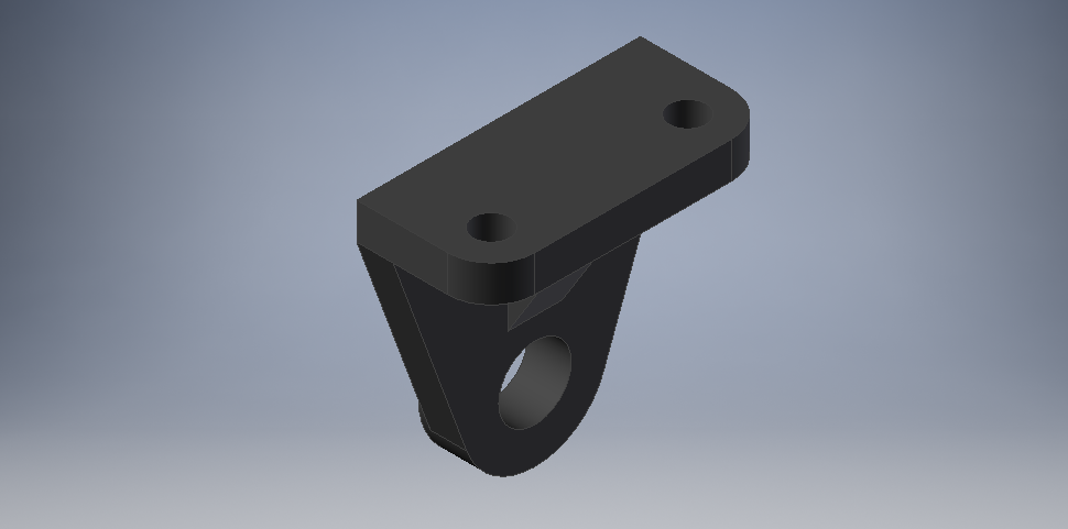
Step by step on how to model a bracket in Autodesk Inventor.
Open Autodesk Inventor

Open your Autodesk Inventor application on your laptop. It should look something like the logo presented above.
Create a New File
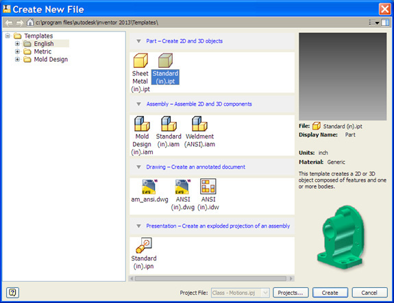
When your application has fully loaded, click file -> new -> standard (in.)-> create.
Start Your First Sketch
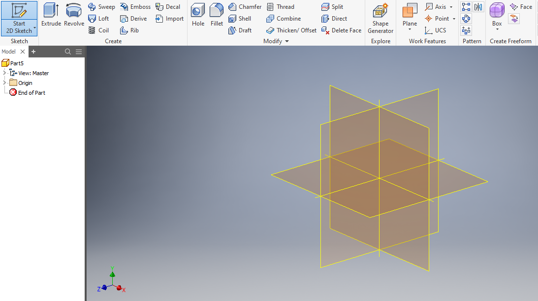
Click the "Start 2D Sketch" button in the top left corner of your screen. After clicking this your screen should look somewhat like the one shown above.
Select the XZ Plane
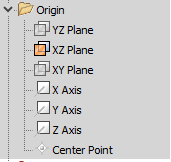
Select the XZ plane. You can select this by moving your cursor to the left side of your screen, hitting thew down arrow on the "origin" tab, and selecting the XZ plane (as shown above). Or, you can select the XZ plane on the drawing in the center of your screen.
Adding Dimensions and a Rectangle
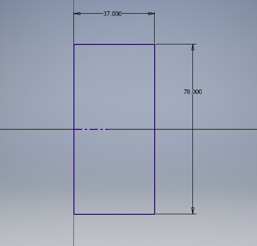
By selecting the rectangle option from the ribbon at the top of your screen, you can draw a rectangle that is aligned with the centerline, as shown above. Add the 2 dimensions shown by selecting the "dimensions" tab in the ribbon.
Extrude the Sketch
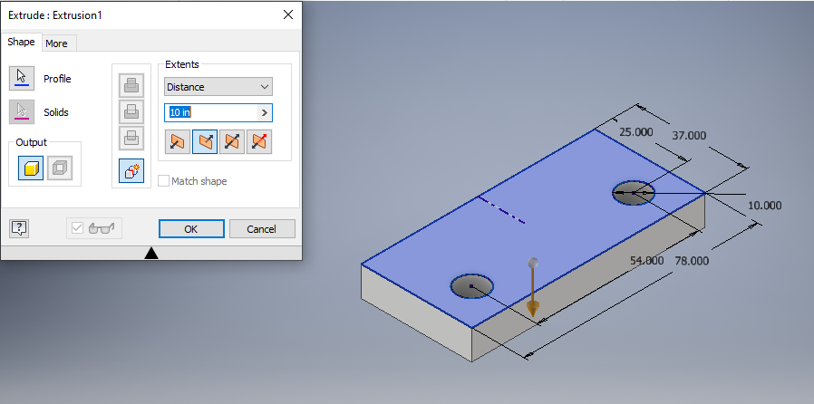
When you have finished adding dimensions, click "Finish Sketch" and then click "extrude". Change the height of the extrusion to 10 in. Then hit "ok"
Start a New Sketch
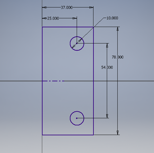
click "Start 2D Sketch" again. Then select the top surface of the shape you just created. Then add the following shapes and dimensions.
Add Fillets
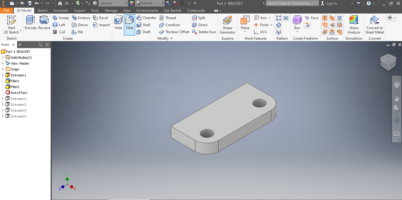
After finishing the sketch, use the fillet tool to create two fillets on the corners shown in the picture.
Start Next Sketch
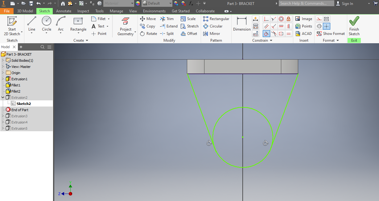
Select "Create 2D Sketch" again. Select the bottom of the surface. Draw out the shape shown above. Use the tangent tool to attach the circle to the lines. Make sure to connect all the lines to create a closed shape.
Trim the Circle
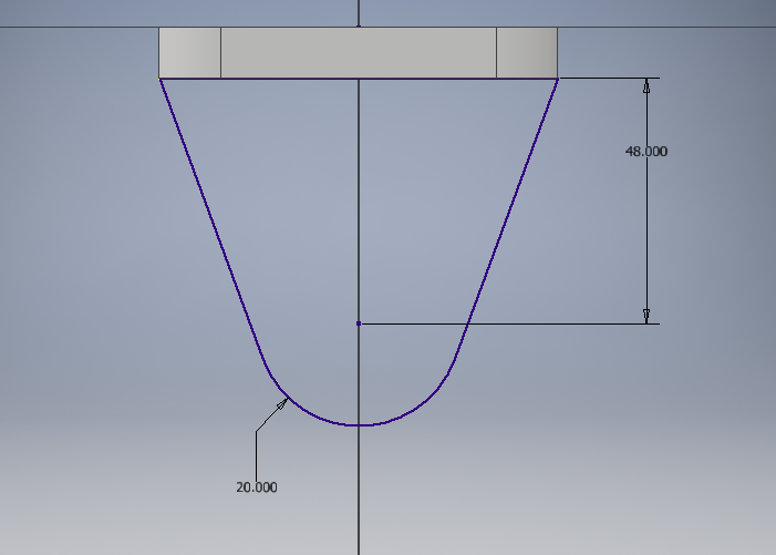
Use the trim tool to trim the side of the circle on the inside of the sketch.
Extrude the Shape
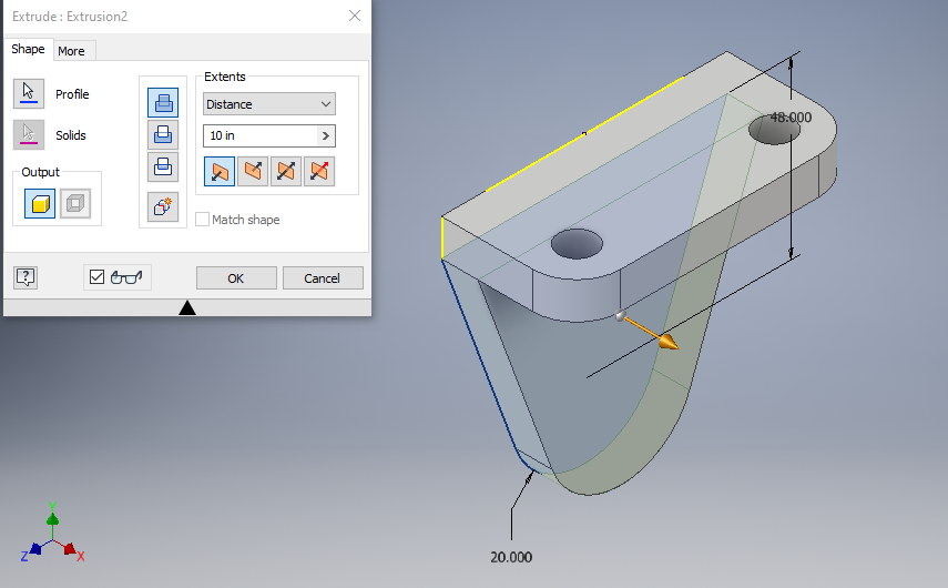
Use the extrude tool again. Keep the length at 10 in. Press ok.
Create a New Sketch
Create a new sketch using the "Start 2D Sketch" button again. Draw a circle
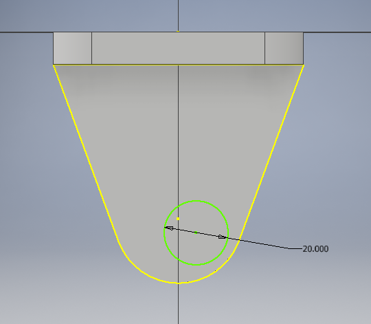
Add Dimensions and Constraints
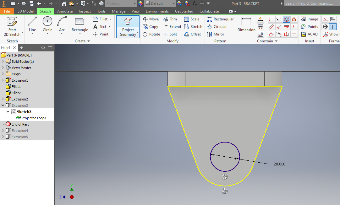
Add a concentric constraint to the new circle connected to the rounded edge. Add the dimension shown in the picture above.
Extrude Cut New Circle
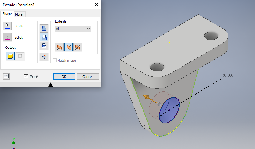
Use the cut command on the extrude tab to cut a circle into the shape.
Create Sketch on XY Plane
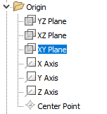
Use the origin drop-down on the left of the screen to select the XY plane after selecting "Start 2D Sketch".
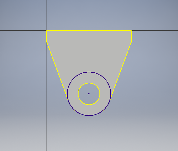
Draw New Sketch
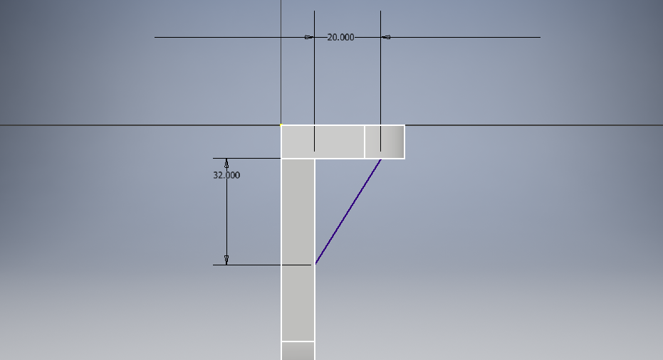
Draw this triangle sketch in the new 2D sketch.
Extrude Sketch
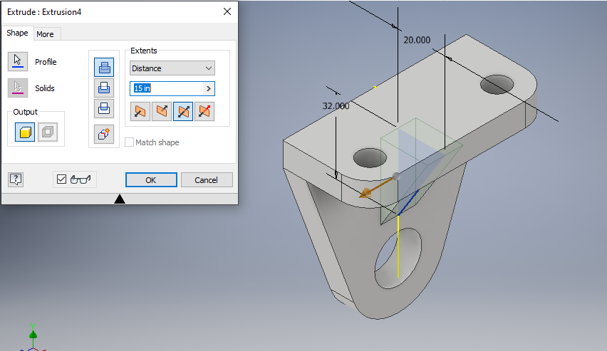
Use the extrude tool to create a 15-inch shape. Use the symmetric option to center the shape.
One Last Sketch
Create one last sketch on the back of the shape. Draw a circle and use the concentric constraint to align it with the rounded edge. Use the equal tool to make the new circle the same dimension as the original.
Extrude Last Sketch
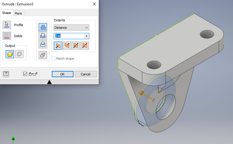
Extrude the last sketch outwards after finishing the sketch. Extrude 2 inches.
Save Bracket
Save the bracket file using the save icon at the top left of the screen.