Boxxer the Battle Bot. (Esp32)
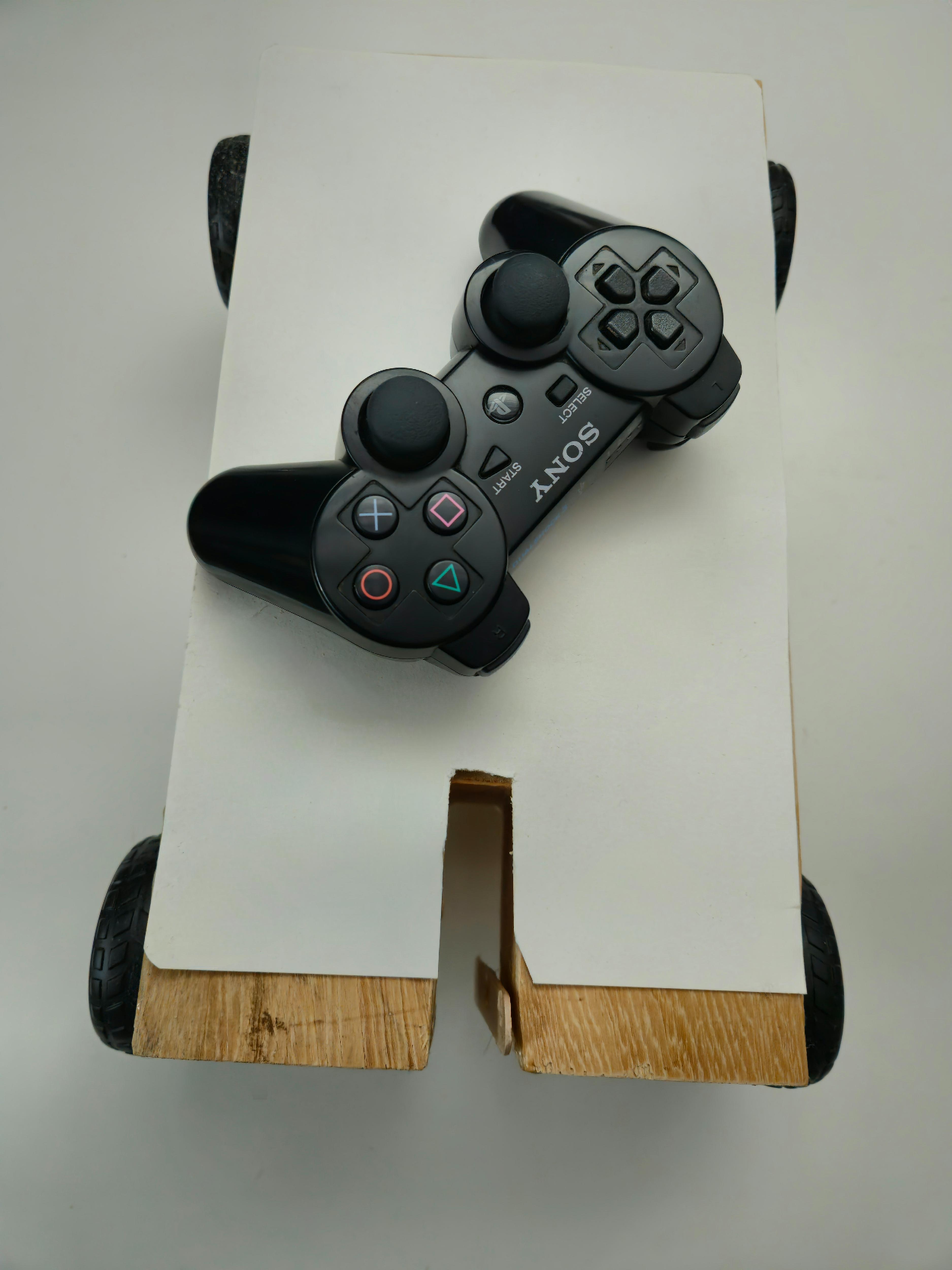
A DualShock 3 controlled battle bot using esp32.
For my school project I had to make something using an Arduino.
After browsing the instructible site, I stumbled across someone that made an autonomous bot. This (and perhaps a few too many battle bot videos) inspired me to make a DualShock controlled battle bot. I've been fascinated by battle bots for quite some time, so it seemed like the perfect project. It's not something I had done before, so I did some research to determine whether or not it would be plausible and turns out it most certainly is. In the end I did not make something nearly as powerful as the ones you would find in a battle arena, which in all fairness I never expected to do in the first place, but it was a blast to work on and it was fun to learn.
I wasn't as familiar with certain aspects of this project like certain parts of the electronics and I had never soldered before, as such I made a multitude of little mess ups, but although some parts not ideal, I got it working in the end.
Downloads
Supplies
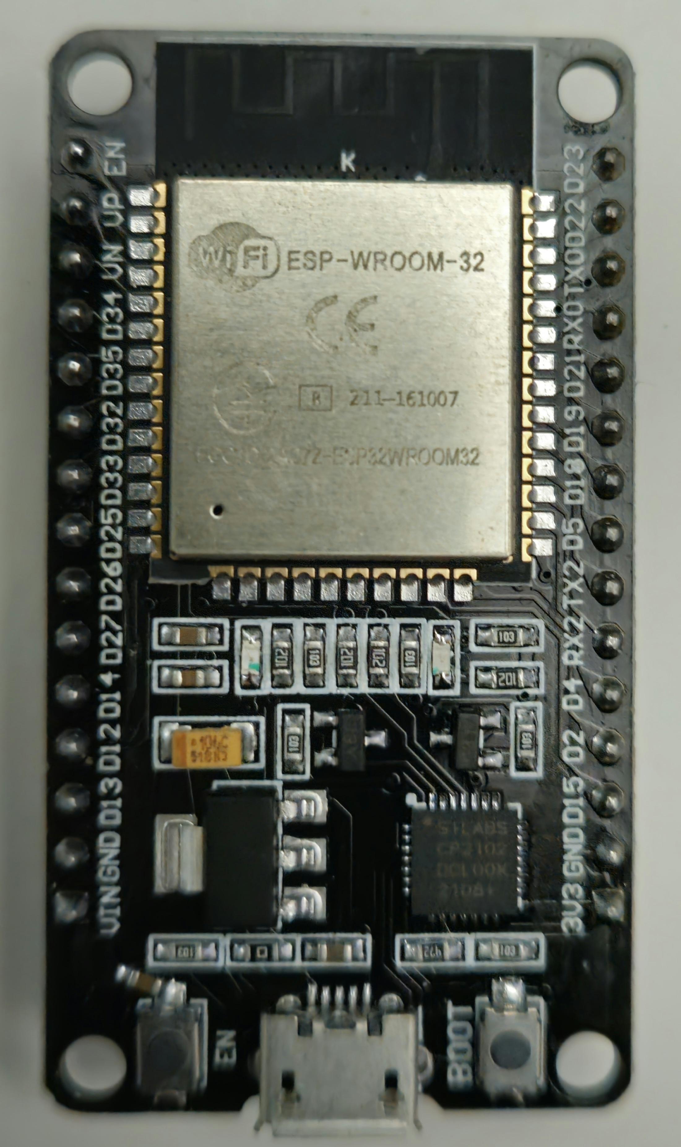
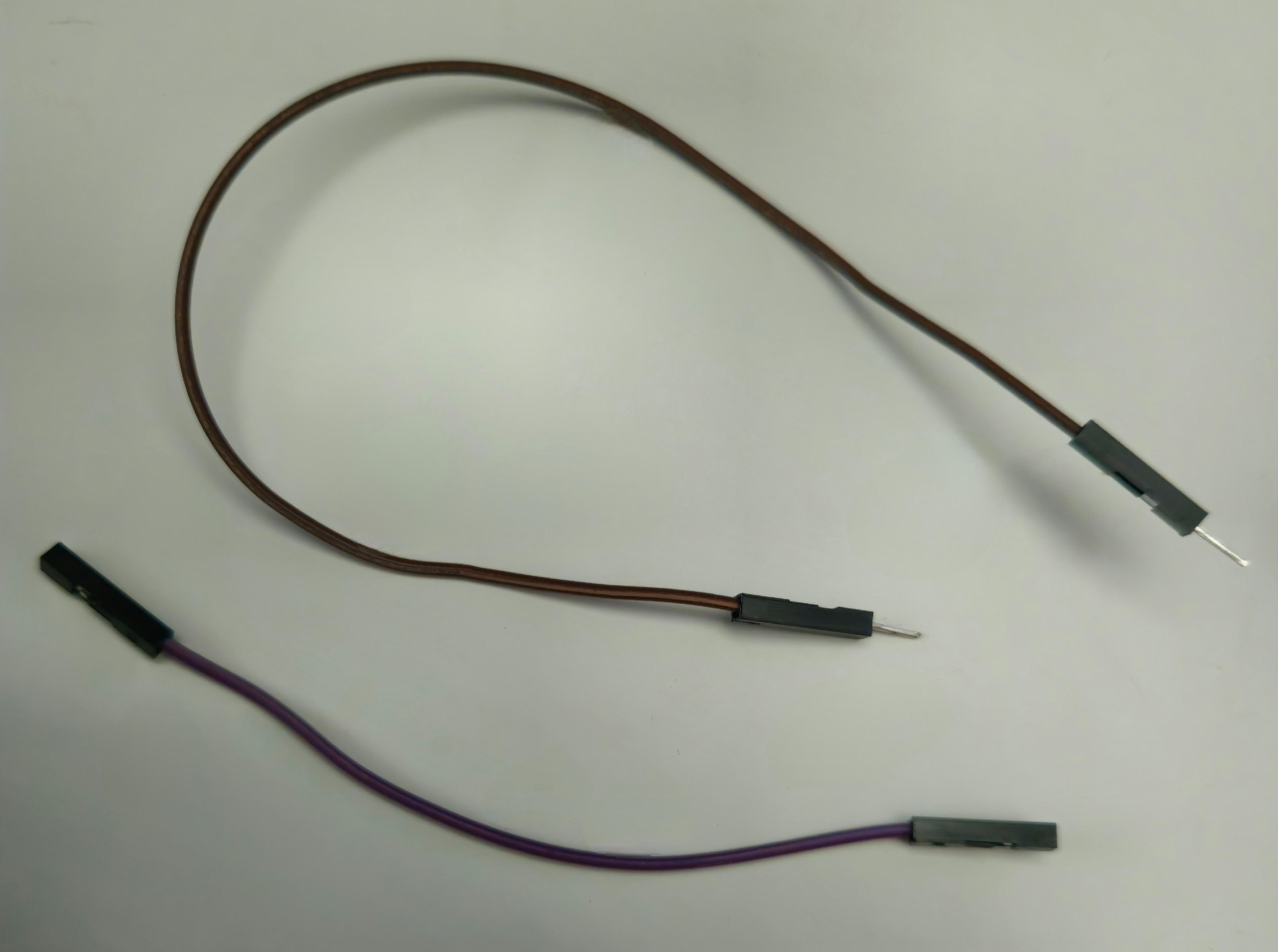
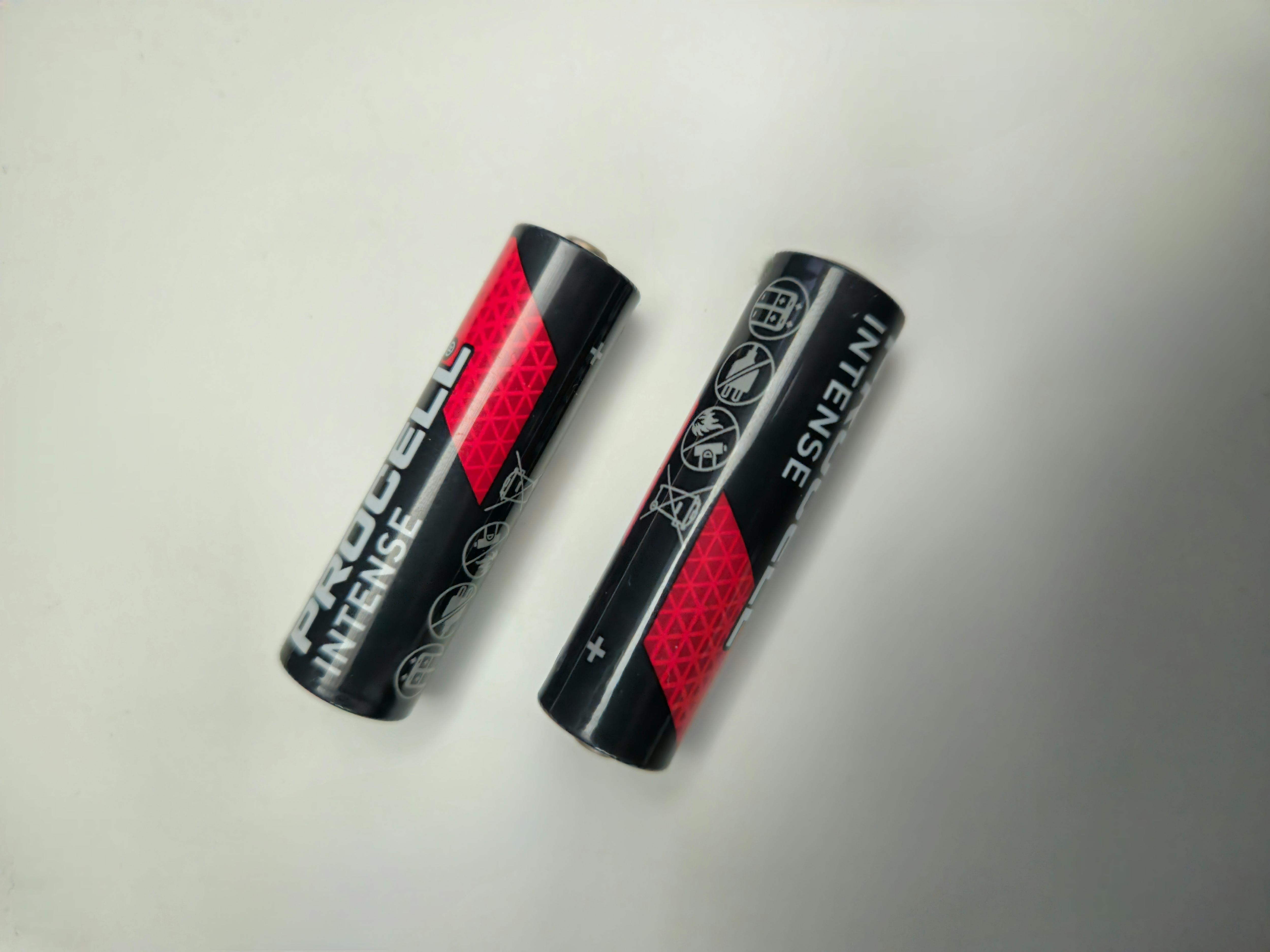
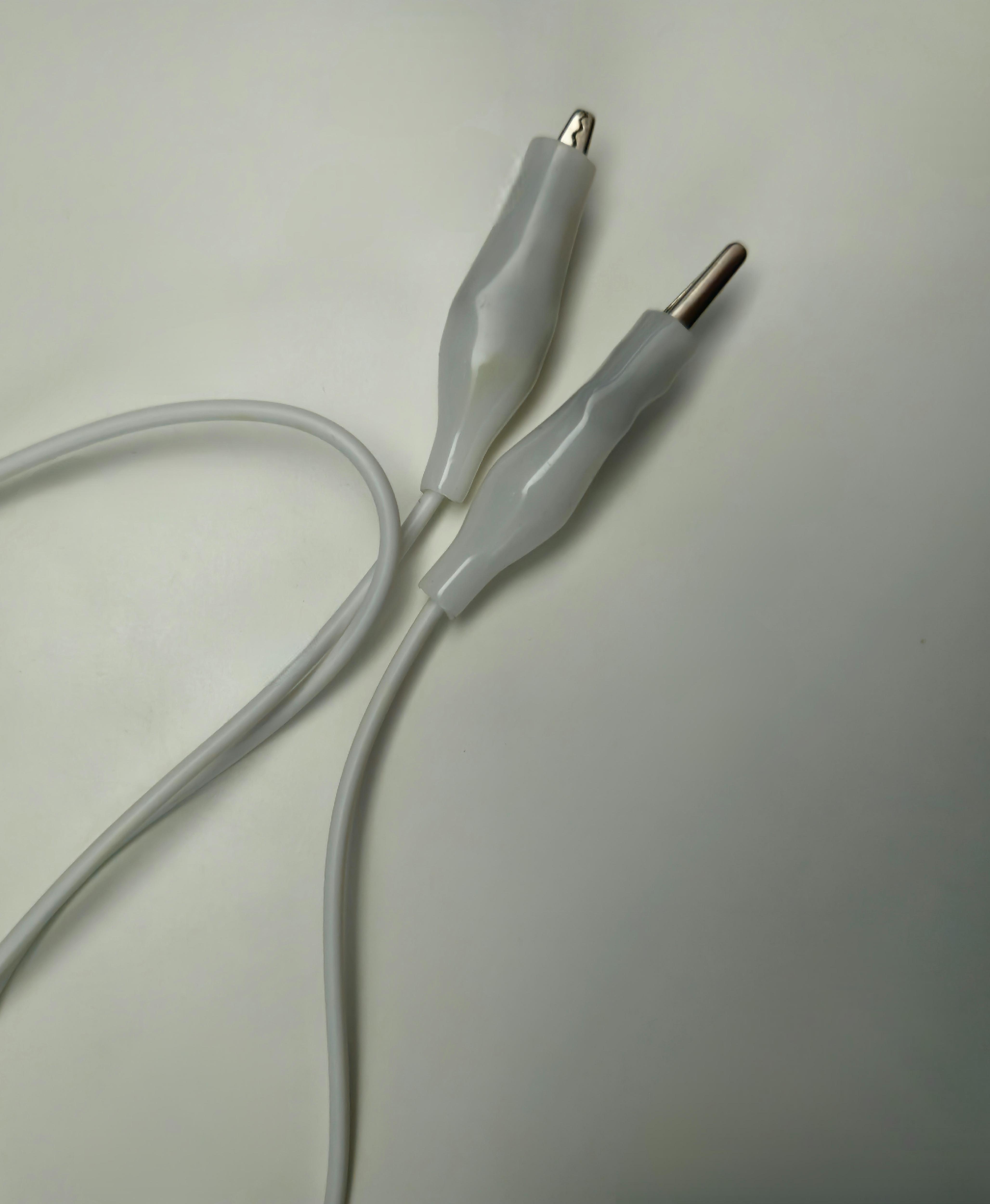
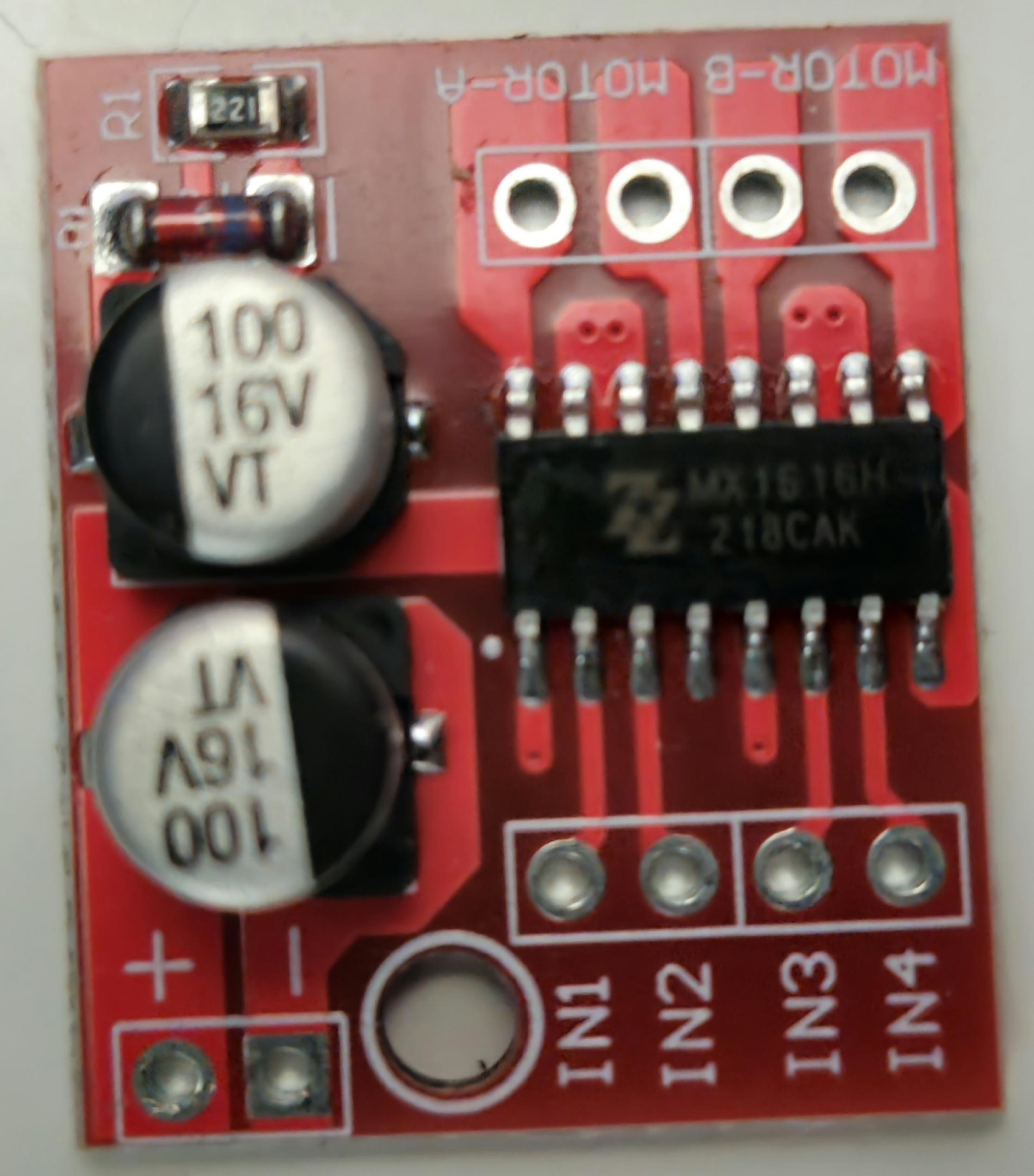
There will be multiple things that you would need to replicate this project. Some of these are Optional.
- An esp32 board with built in Bluetooth and a Micro-Usb cable.
- 2 Motor drivers, I used 2 mx1508's, which supports a roughly 1.2-1.5A continuous load per channel. This isn't ideal for one of the motors but I got it to work in the end. (This part depends on which motor you intend on using.)
- A DualShock 3 controller.
- A computer.
- A powerbank, I used a pretty small 2000mah one.
- A battery holder of at least 4 AA slots in series, I used a battery holder of 6 but 4 should be sufficient.
- 4 AA batteries, I used 6 but 4 should be sufficient.
- Wire strippers. (Alternatively you could use regular pliers or something similar.)
- Soldering iron + solder with flux.
- "Male to female" + "female to female" Jumper wires.
- Aligator clip wires. (You can use regular jumper wires instead if preferred.).
- A sheet of plywood or an alternative.
- A saw, I used a figure saw but a different one might be preferred.
- A sheet of paper. (Optional)
- 4 motors + wheels. I used DC Gearbox motors "TT motors" with a gear ratio of 120:1.
- One motor for the weapon. I used a 6v DC motor.
- A switch for turning off the power to the motors.
- Cable ties. (Optional)
- Some form of glue or alternative. (I used construction glue.)
- Some electrical tape or shrink wrap.
- Some patience. (Optional but quite convenient)
- Breadboard. (Used during the testing.)
Setting Up the Esp32 in Arduino IDE
Here follow the instructions on how I built this project so that you could replicate it.
The first step will be preparing the IDE for the use of the esp32. I will be using the Arduino IDE.
Open your Arduino IDE, if you have not installed it yet, install it first, I used version 1.8.19. Go to your preferences tab (the shortcut for it is Ctrl + Comma, alternatively it can be found under the "File" tab).
Then under the "Additional Boards Manager URL" I added the following URLs: https://raw.githubusercontent.com/espressif/arduino-esp32/gh-pages/package_esp32_index.json and http://arduino.esp8266.com/stable/package_esp8266com_index.json. You can separate them by using a , .
After which you can go to "Tools" -> "Boards" -> "Boards Manager", then search for Esp32 and press install. After plugging the Esp32 into the computer you should now be able to select it under the boards menu.
That concludes setting up the Arduino IDE for the esp32. Do note, that when uploading a sketch to the esp32 you need to hold the Boot button, otherwise it won't be able to properly upload the sketch.
Connecting the DualShock 3 Controller
In order to use the DualShock 3 controller with the esp32 you will need to install the following library:
https://github.com/jvpernis/esp32-ps3
In order to install the library you need to go to "Sketch" -> "Include" -> "Manage Libraries", then search for "PS3 Controller Host" and click install.
After installing the library you can include it in your sketch by going "Sketch" -> "Include" -> "PS3 Controller Host".
You then have to add the following line to the sketch:
#include <Ps3Controller.h>

void setup()
{
Ps3.begin("Mac Address");
}
In order to get the mac address ,we will use to connect the DualShock 3 controller, we can use a tool called "Sixaxis pair tool".
Plug the DualShock 3 controller into the computer and then open the pairing tool. Once opened, you can see and edit the mac address the controller uses, we can change this to match the one we've set in the code of the esp32.
Without this step the DualShock 3 controller will not be able to connect to the esp32.
(I will share all of the code I made in the upcoming step.)
Testing, Iterating, Writing the Code.
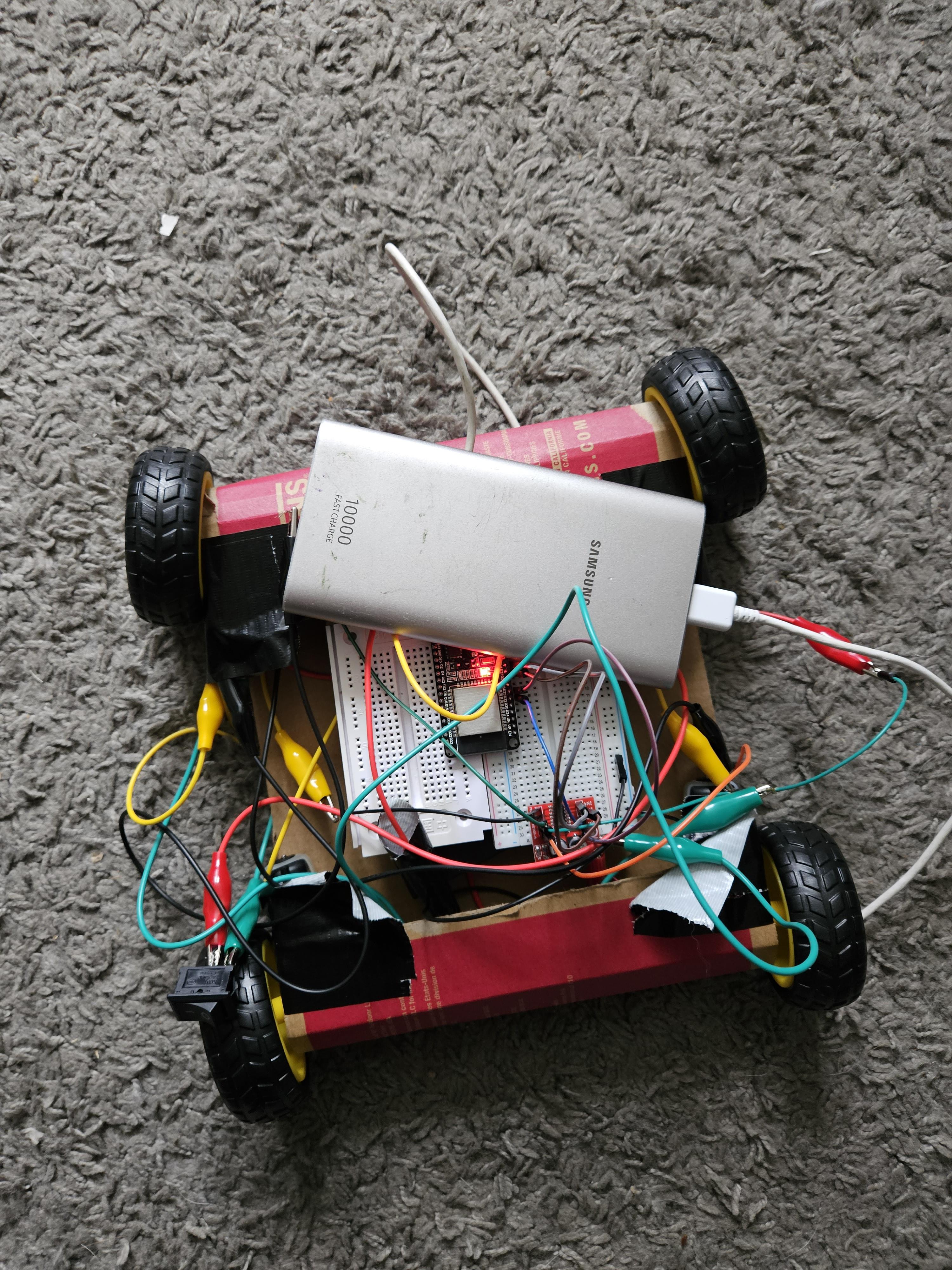
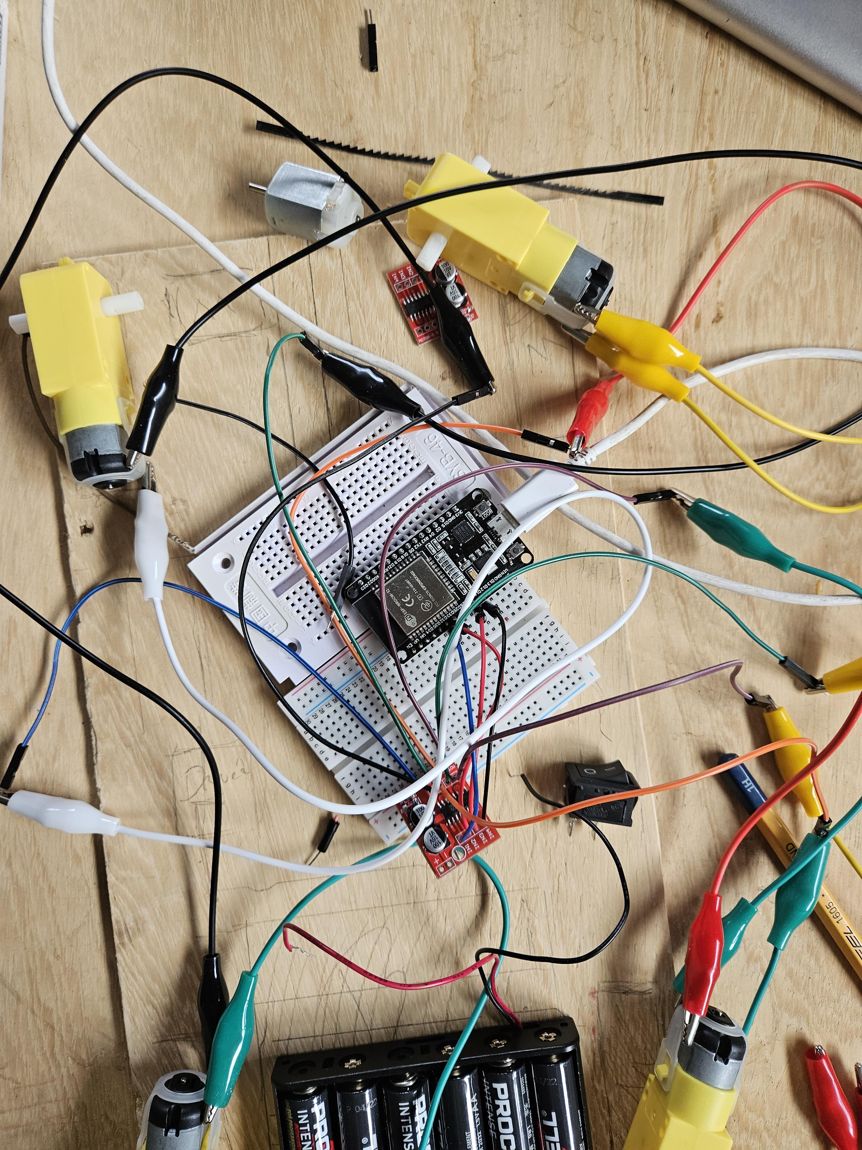
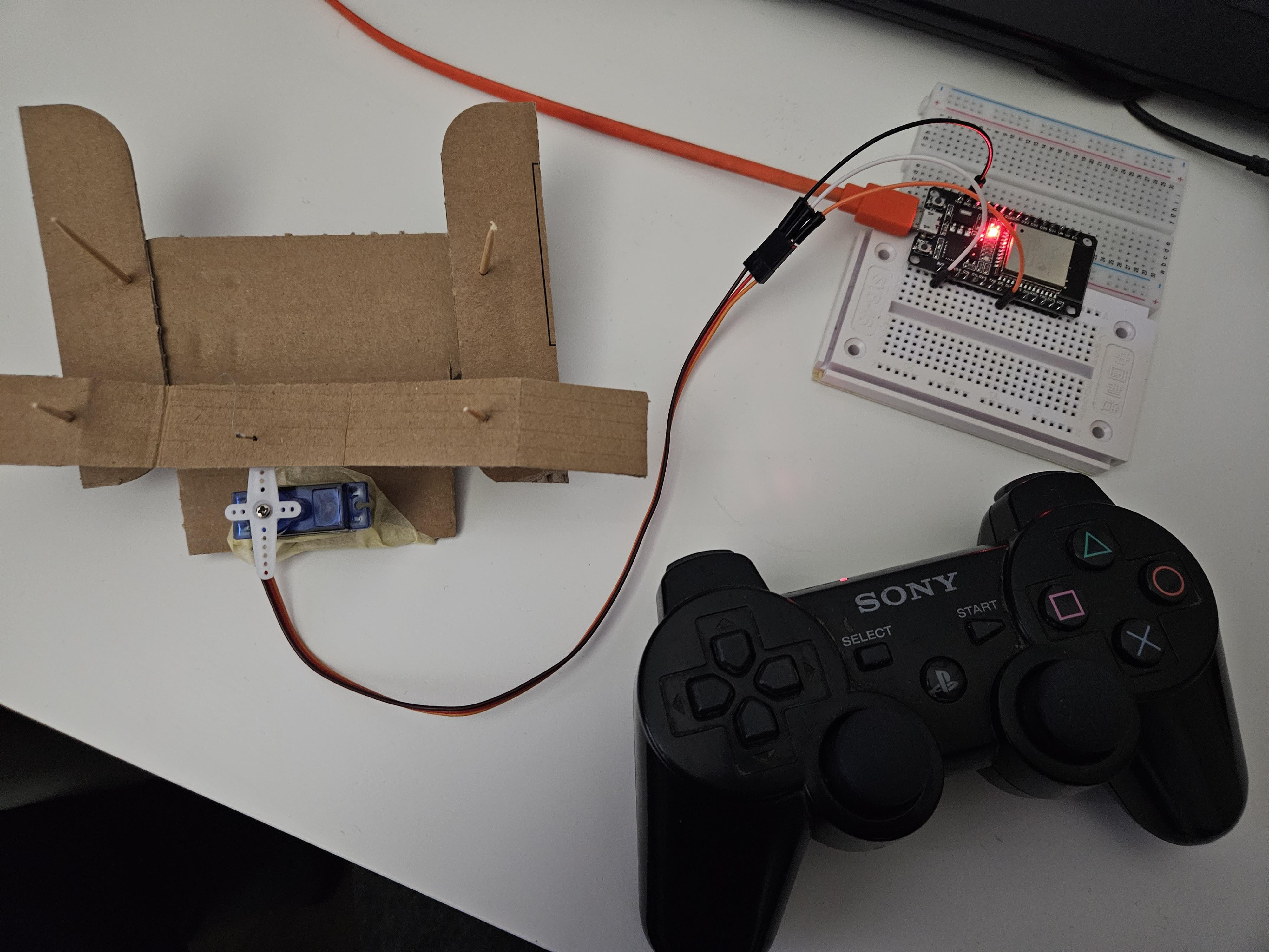
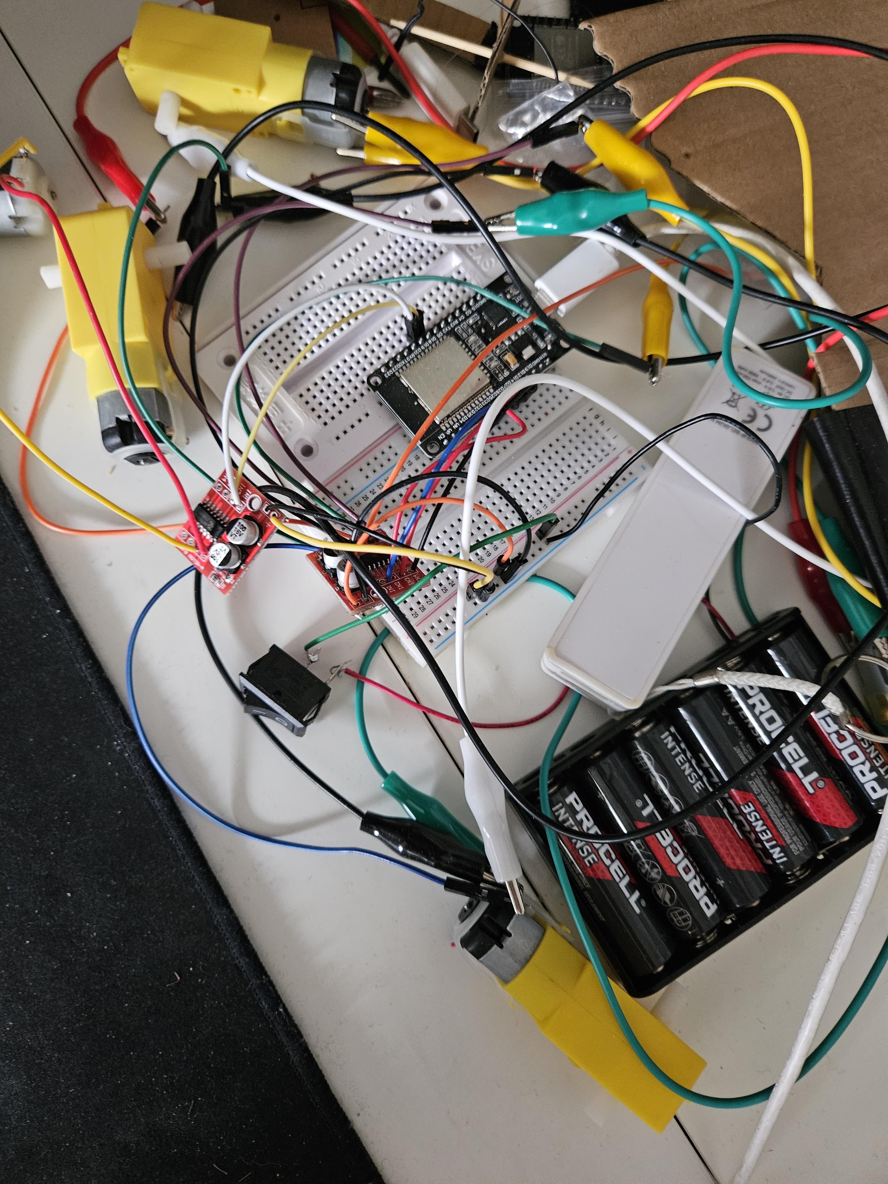
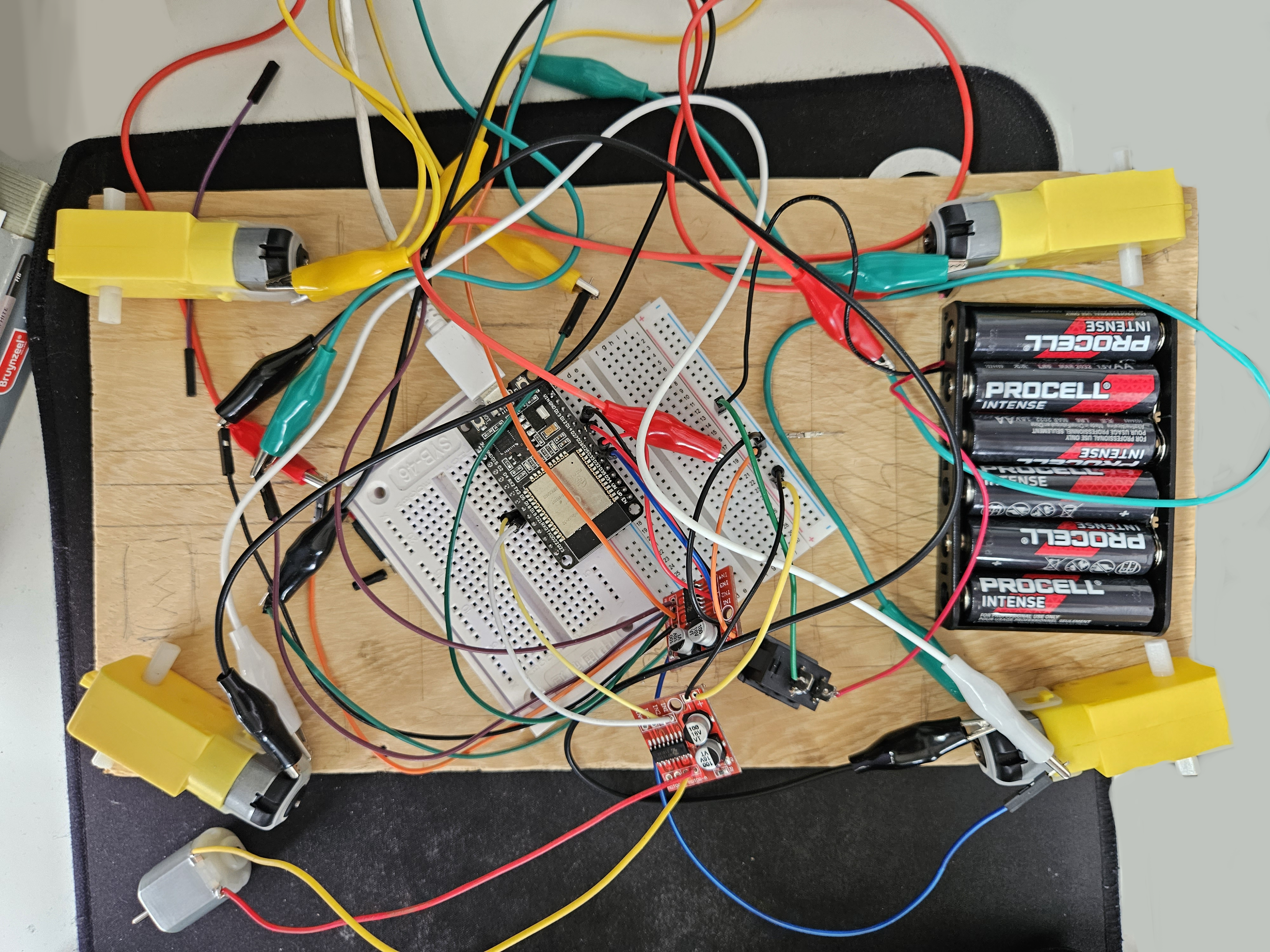
In this step I tested the basic function outside of a case and did some iterating, during this I used a temporary breadboard which would later be replaced by soldering. I also tested the function with a little cardboard contraption, this does not have to be replicated.
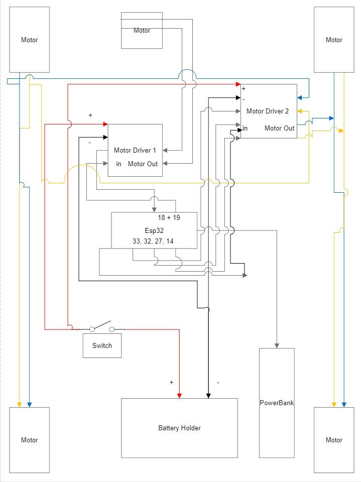
The first iteration of the design used a single motor and a servo system for the steering, as shown in the image. While I got it working, I later decided on scrapping this idea and going for 4 wheel drive instead, the single motor did not quite have enough power and the steering wasn't quite sharp enough for my liking, additionally if the one motor were to fail the bot would no longer be able to move, which it still can if one of the 4 motors fails. (The Schematics have been placed separately in the next step.)
I wrote the rest of the code during this step as well. The code goes as followed:
#include <Ps3Controller.h>

int leftVertical;
int rightVertical;

int ds3Triangle;

int pinIn1 = 27;
int pinIn2 = 14;

int deadZone = 40;
int attackMotorEnabled = 0;

int pinIn3 = 33;
int pinIn4 = 32;

int pinIn5 = 18;
int pinIn6 = 19;

void notify()
{
 leftVertical = (Ps3.data.analog.stick.ly);

 rightVertical = (Ps3.data.analog.stick.ry);
 int engineValueRight = map(rightVertical, 0 , 128, 0, 255);
 int engineValueLeft = map(leftVertical, 0 , 128, 0, 255);
 ds3Triangle = (Ps3.event.button_down.triangle);

 if (attackMotorEnabled == 0 && ds3Triangle == 1)
 {
  analogWrite(pinIn5, 127);
  digitalWrite(pinIn6, LOW);
  attackMotorEnabled = 1;
 }
 else if (attackMotorEnabled == 1 && ds3Triangle == 1)
 {
  analogWrite(pinIn5, 0);
  digitalWrite(pinIn6, LOW);
  attackMotorEnabled = 0;
 }

 if (rightVertical < -deadZone)
 {
  digitalWrite(pinIn1, LOW);
  analogWrite(pinIn2, abs(engineValueRight));
 }
 if (rightVertical > deadZone)
 {
  analogWrite(pinIn1, abs(engineValueRight));
  digitalWrite(pinIn2, LOW);
 }

 if (abs(rightVertical) < deadZone)
 {
  analogWrite(pinIn1, 0);
  analogWrite(pinIn2, 0);
 }

 if (leftVertical < -deadZone)
 {
  digitalWrite(pinIn3, LOW);
  analogWrite(pinIn4, abs(engineValueLeft));
 }
 if (leftVertical > deadZone)
 {
  analogWrite(pinIn3, abs(engineValueLeft));
  digitalWrite(pinIn4, LOW);
 }

 if (abs(leftVertical) < deadZone)
 {
  analogWrite(pinIn3, 0);
  analogWrite(pinIn4, 0);
 }
}

void setup() {
 Ps3.attach(notify);
 Ps3.begin("44:d8:32:c8:8d:1a");

 pinMode(pinIn1, OUTPUT);
 pinMode(pinIn2, OUTPUT);

 pinMode(pinIn3, OUTPUT);
 pinMode(pinIn4, OUTPUT);

 pinMode(pinIn5, OUTPUT);
 pinMode(pinIn6, OUTPUT);
}

void loop() {
 if (!Ps3.isConnected())
 {
  return;
 }
 delay(2000);
}
To summarize the functionality:
When you press the Triangle button it will toggle the weapon's motor on or off, depending on it's current state.
You can use the right analog stick to control the 2 motors on the right side of the Battle bot, and the left analog stick for the motors on the left side of the bot. Moving the analog stick forward will make the battle bot go forward and vice-versa.
If you want to turn, you can inverse the two inputs, right forward and left backwards as example will make the battle bot turn to the left.
The deadzone determines how much you need to move the analog stick before it'll be registered. (I set this to counter stick drift.) If there is no input from the analog stick the corresponding motors won't receive any power.
You can control the amount of throttle by varying the amount at which you move the analog stick.
The abs() function is used to make sure we don't get a negative value. The value range of the DualShock 3's analog stick is by default roughly 128-> -128.
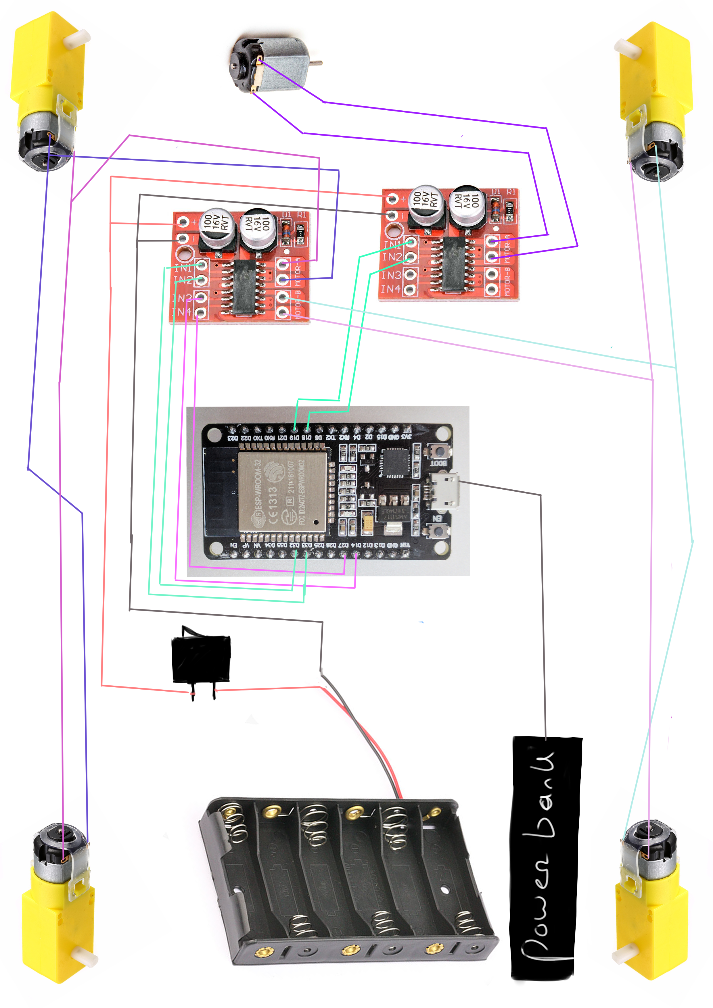
Here follows the schematic.
Schematics
Troubleshooting
In this step we'll be doing some quick troubleshooting, if everything is working as intended this step can be skipped, if later down the line problems occur you can return to this step to see potential fixes. It is recommended to do this before soldering, to make sure everything will work.
I will now mention some issues that might occur and how to potentially fix them:
1.Motors on one side go in opposite direction instead of going in the same direction, for instance the front wheel is going forward as intended but the wheel in the back is going backwards. You can fix the motors on one side going in the opposite direction, by inverting the connection to the motor on the motor that is going in the wrong direction.
2.Motors are going in the same direction but not the correct direction. If the motors are not going in the right direction, let's say for instance they are going backwards instead of forward. You can fix this by inverting the connections to the motor or by inverting the code. For example changing:
  digitalWrite(pinIn3, LOW);
  analogWrite(pinIn4, abs(engineValueRight));
To:
  analogWrite(pinIn3, abs(engineValueLeft));
  digitalWrite(pinIn4, LOW);
3.The motors aren't spinning when giving the input. This could be caused by multiple things, maybe the power switch isn't turned on. It could also very well be that there isn't proper contact at some place, for instance in the motor driver output or input, if this is the case moving the wires around a bit could solve the problem. One possible cause could also be that the pins used in the code aren't the same as the pins used to connect the motor driver to the esp32. If this is the case you can adjust the pins in the code by changing the variable to the corresponding pin, or alternatively you can change the pin used on the esp32 to the one that's used in the code.
4.The DualShock 3 controller isn't connecting to the esp32. If the DualShock 3 controller isn't connecting to the esp32, chances are the mac address set in the controller is not matching the one used by the esp32. Changing this value using the Sixaxis pairing tool to the correct address should fix the problem.
5.The sketch isn't uploading to the esp32. If the sketch isn't uploading chances are that the esp32 isn't in it's download mode. Holding down the boot button on the esp32 while uploading should allow it to upload properly.
Soldering
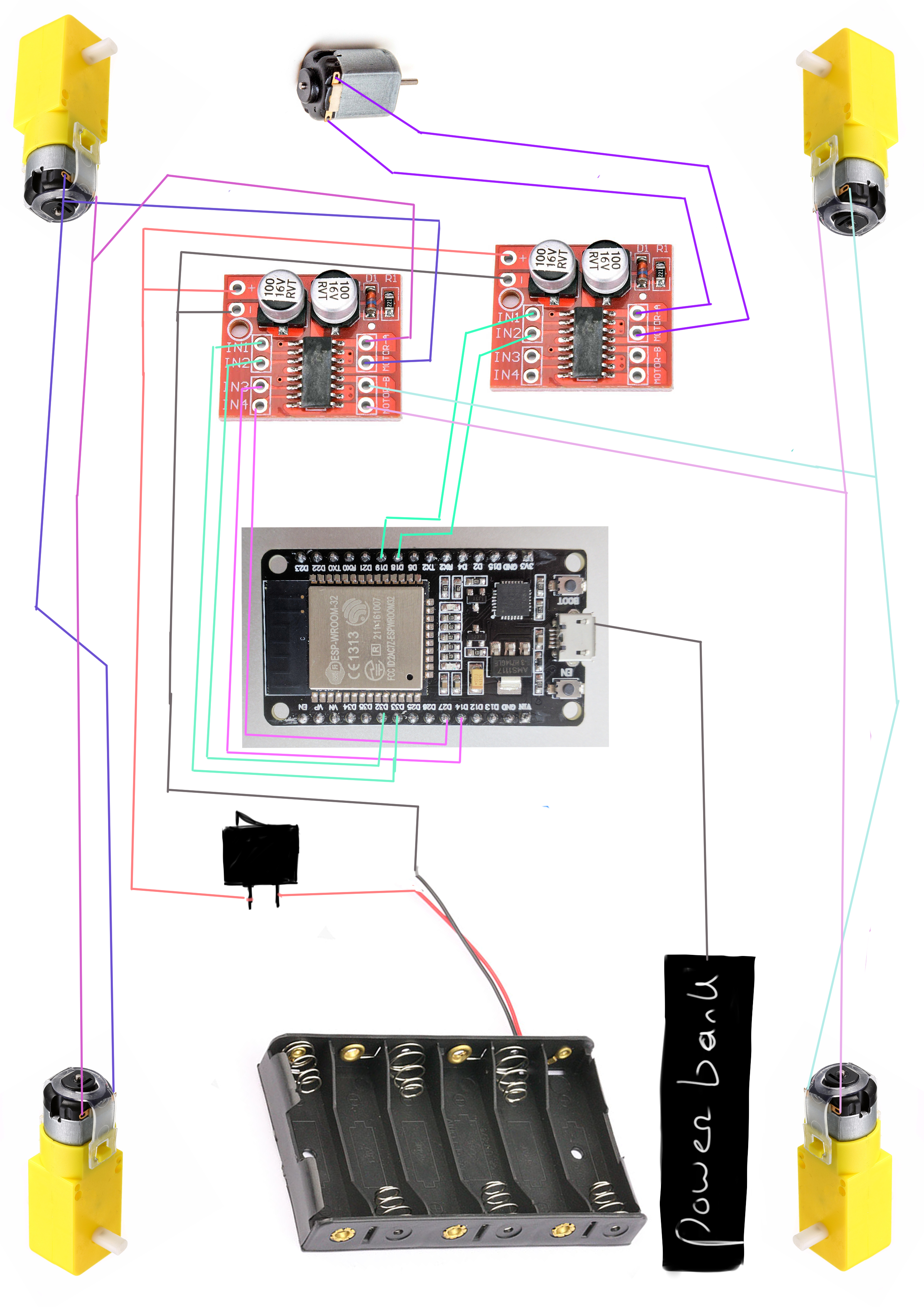
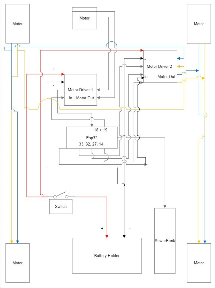
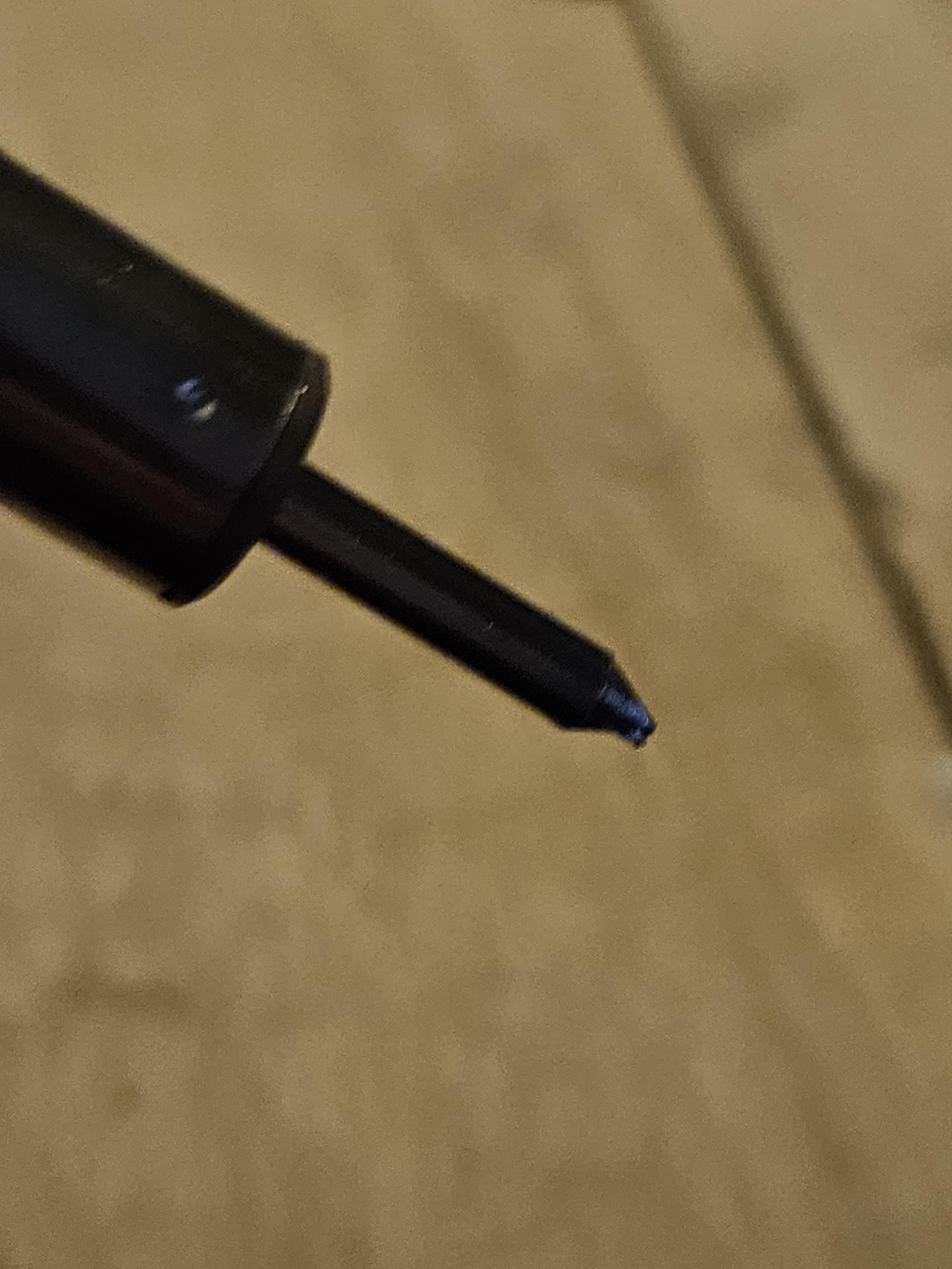
In this step we'll be soldering the wires and connections. If not done before, I recommend testing it first without soldering. Additionally, if you have never soldered before I recommend watching a separate tutorial on that first to get a little more accustomed with it.
Instead of soldering directly to the esp32, I used "female to male" jumper wires, you could alternatively use a soldering board, or solder it directly to the esp32 but the latter of which might not be preferred. The points that need to be connected can be found in the schematics. Before soldering a jumper wire, be sure to strip the wire at the point you intend on soldering it, 1cm should be sufficient. And make sure that wires that shouldn't be connected aren't, as this might cause problems later.
The motor drivers I used are rather small, so if you have it I would recommend using a holder to hold the board in place while soldering. I didn't have one which was rather inconvenient.
Making the Casing
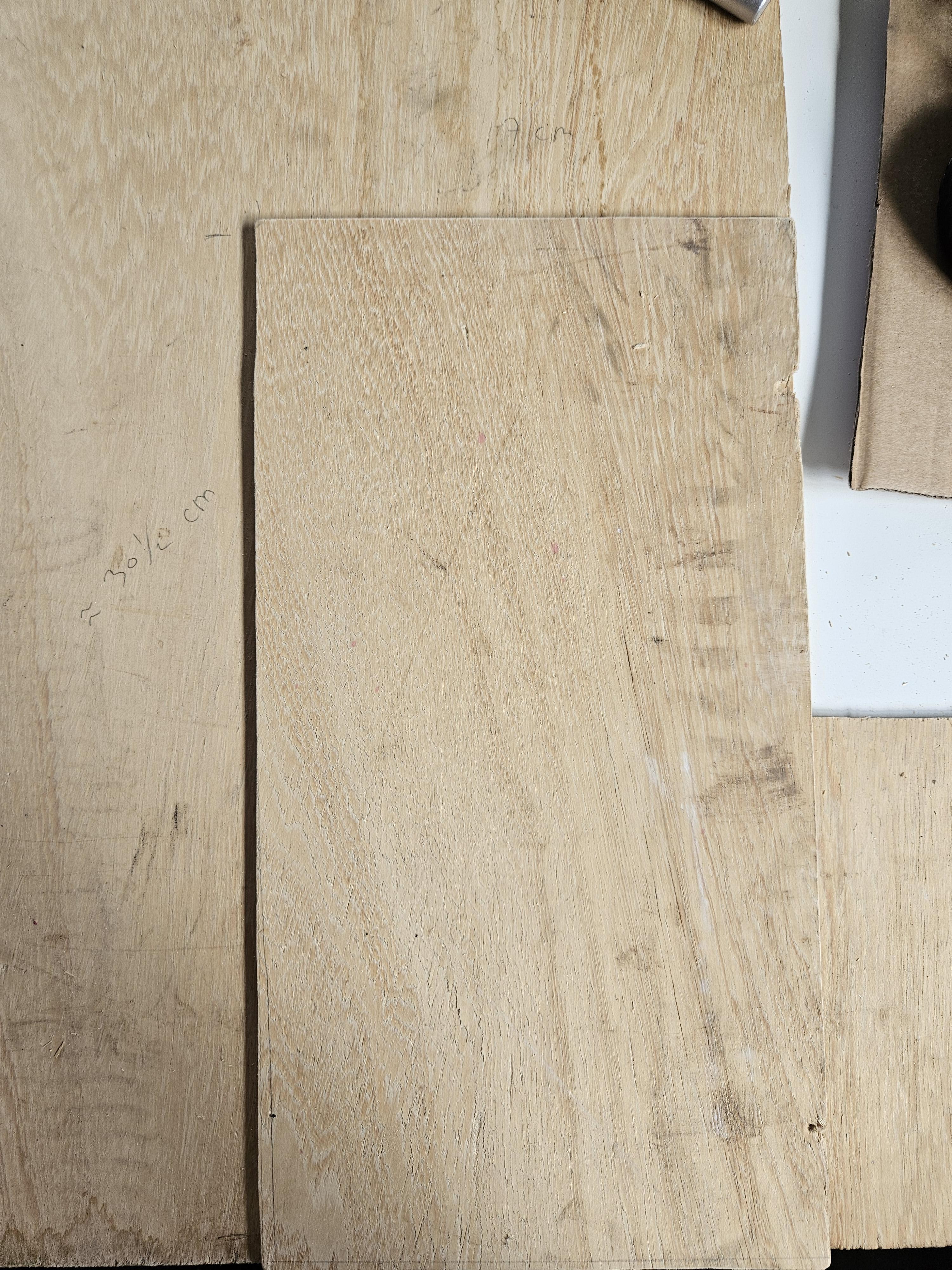
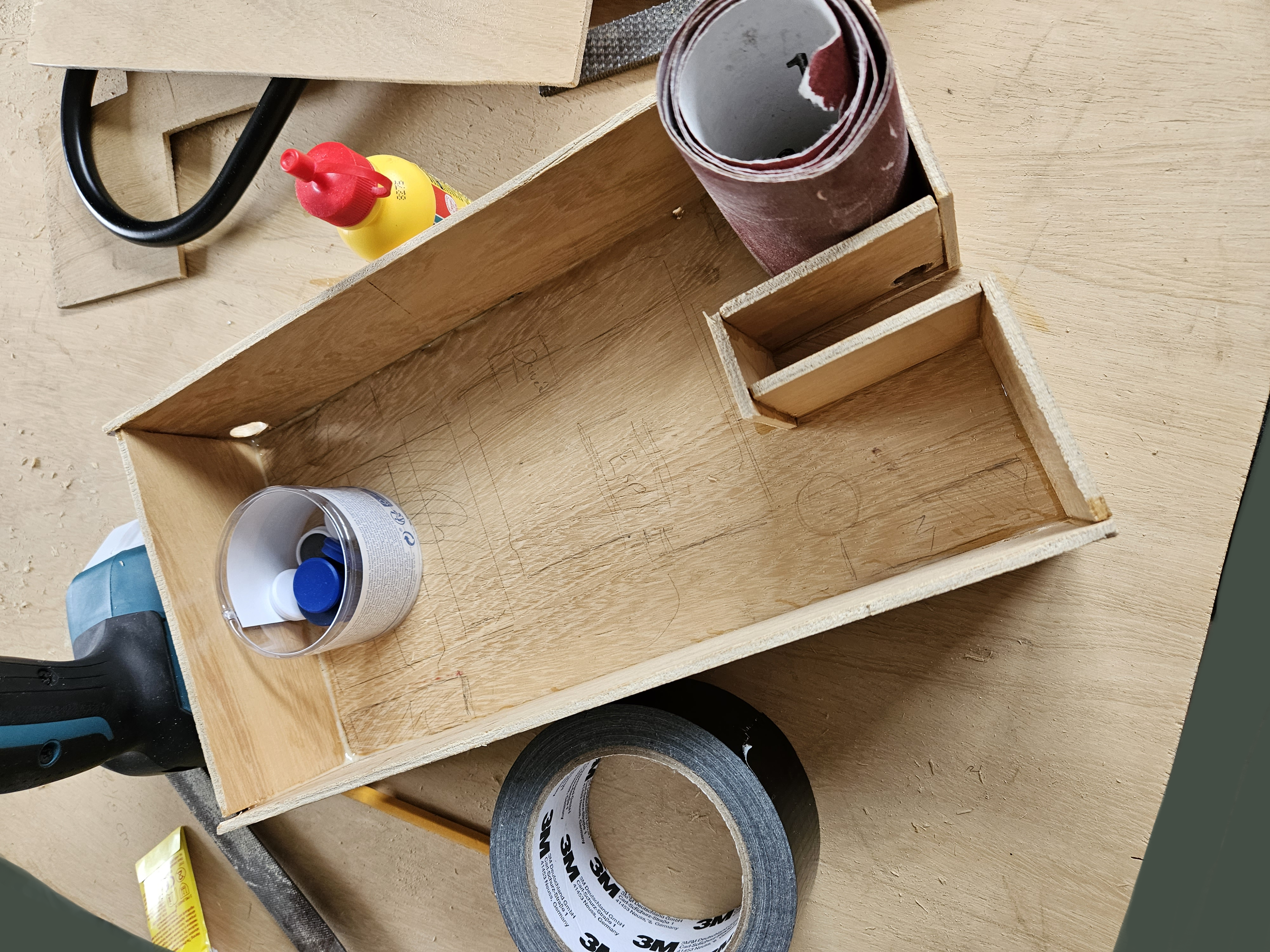
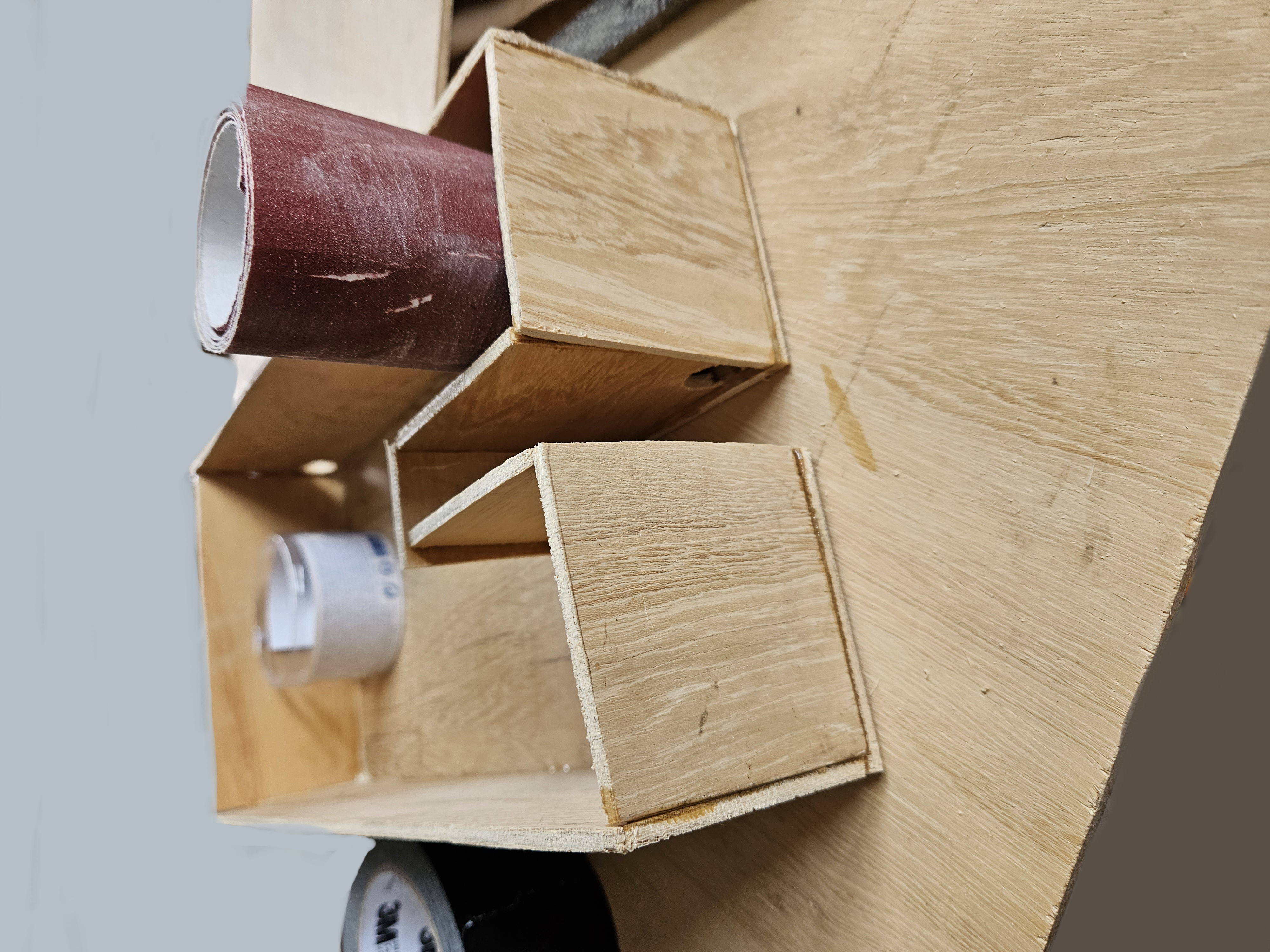
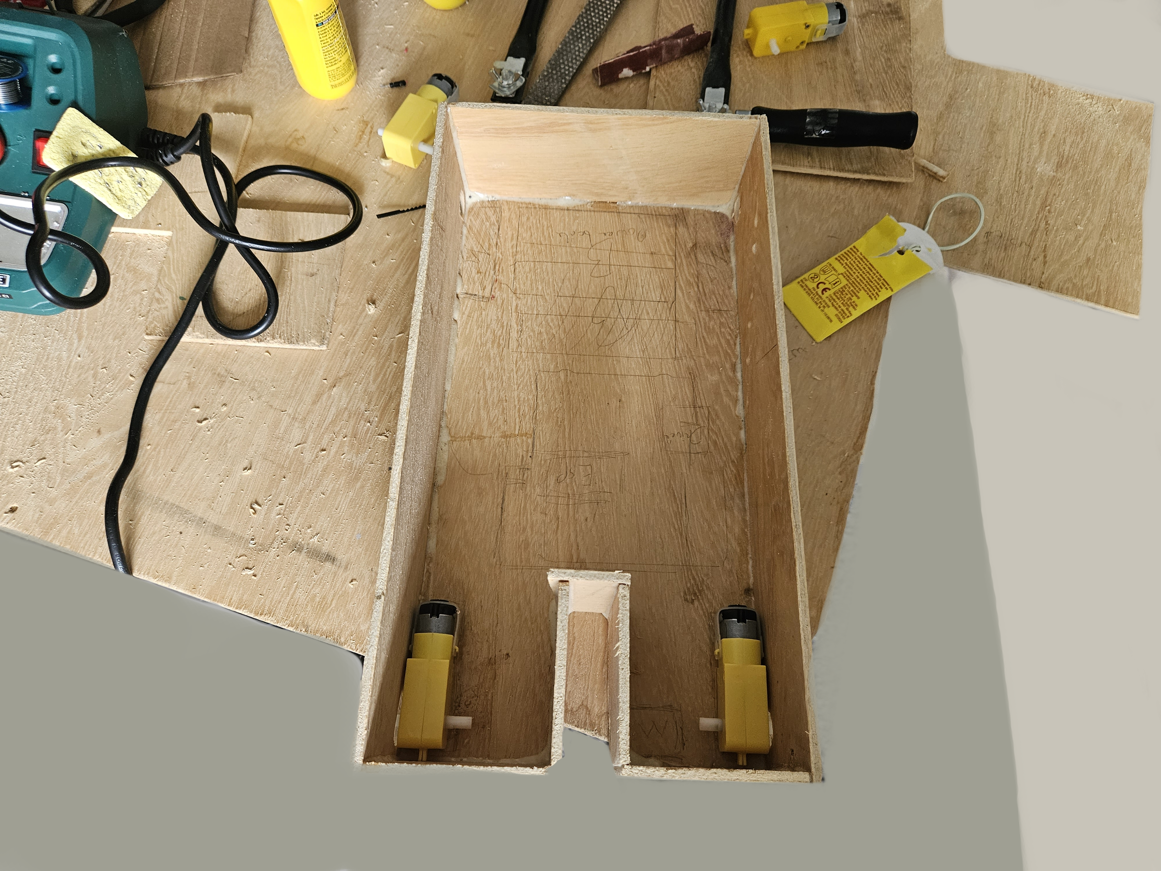
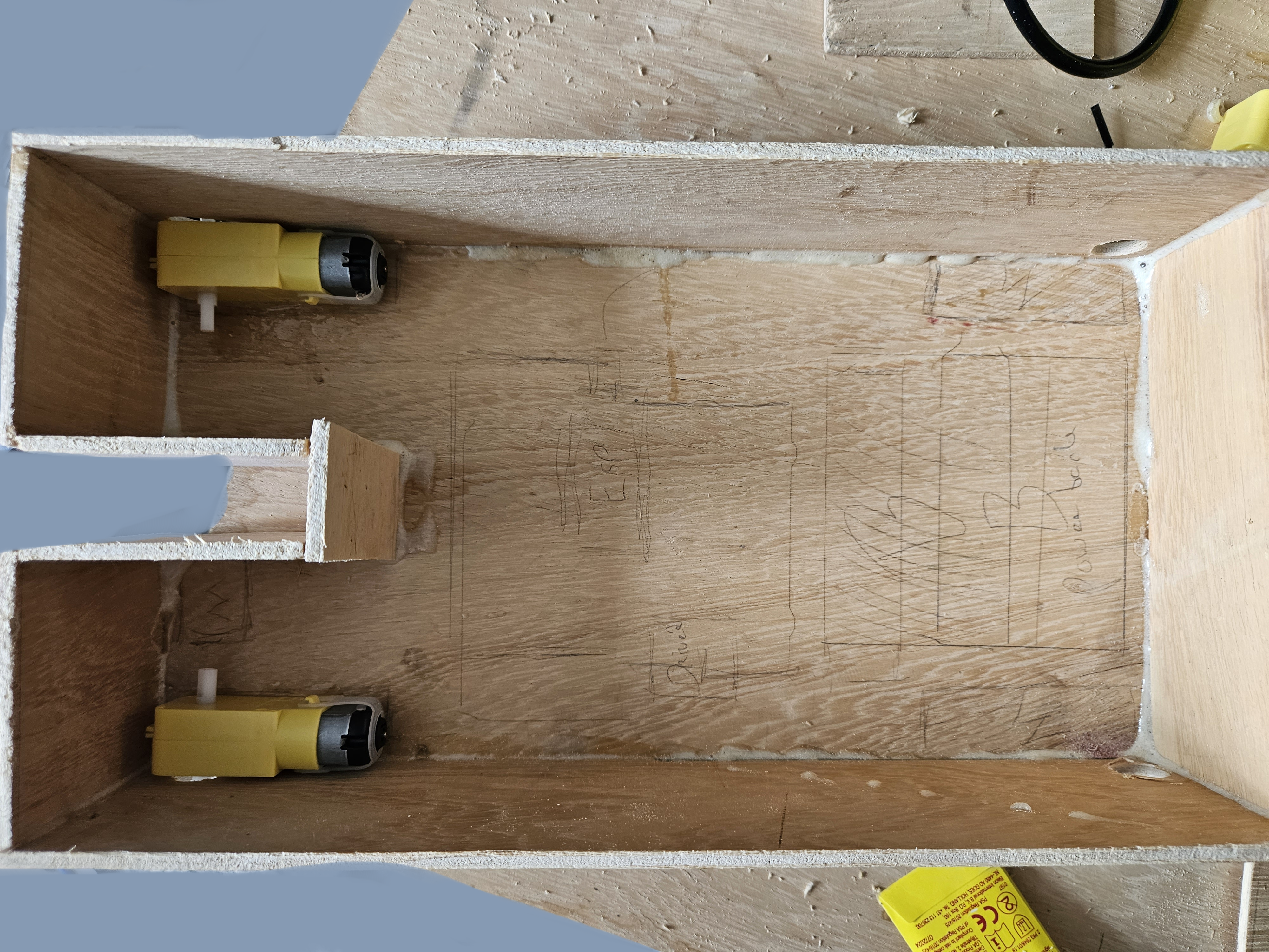
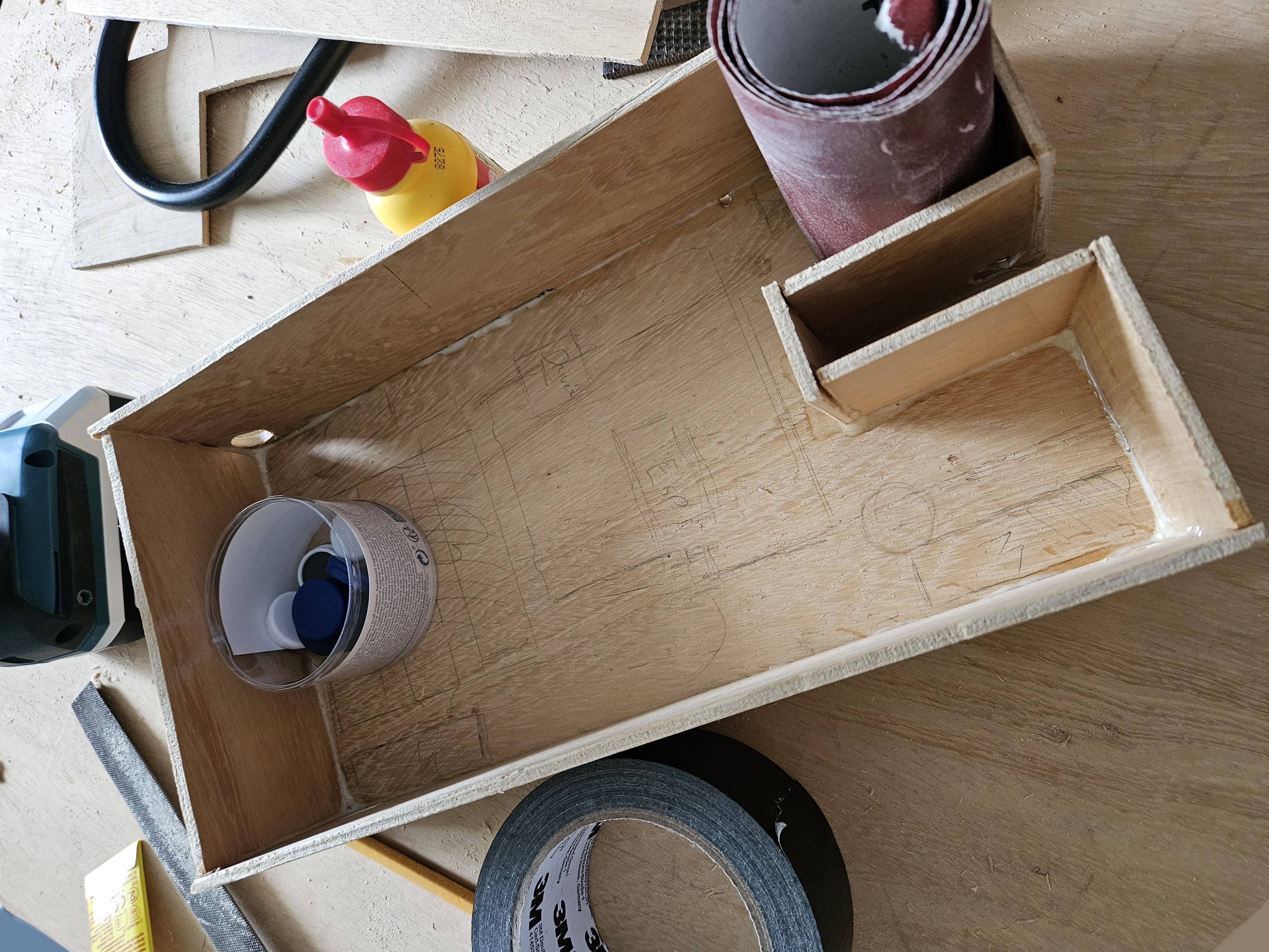
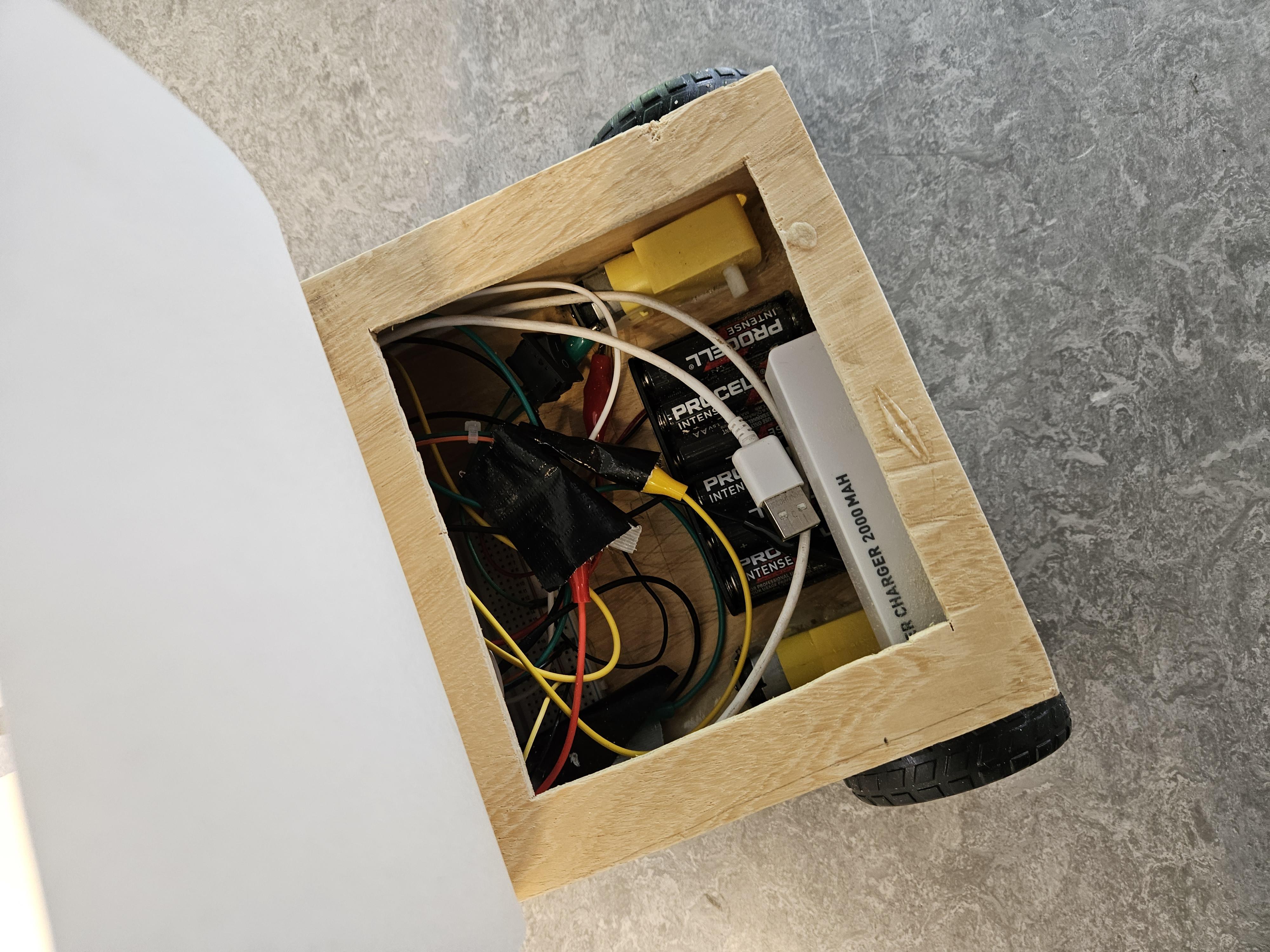
During this step I designed and made the casing for the battle bot. This step will ultimately come down to what you have in mind for the appearance of the battle bot. Alterations I would make if I were to make this again would be more space for the wheels, as they are currently touching the wood which is not ideal. And I would make a sturdier alternative to the current way I made the opening.
After cutting out the wood I glued the pieces together using construction glue. I made sure to make a hole in the top wooden plate, so that I could keep access to the powerbank and battery holder. This is so that I could recharge the powerbank and swap out the batteries if required. I also drilled holes for the wheels and the weapon's motor.
Once the glue had dried I fixed some imperfections by using sawdust and glue to fill little gaps and sand paper and files/rasps to remove excess wood. I initially placed the motor for the weapon too low, as I didn't keep enough consideration in to how high the wheels would elevate it, as such I had to move the motor up a bit as well.
Putting Everything Together
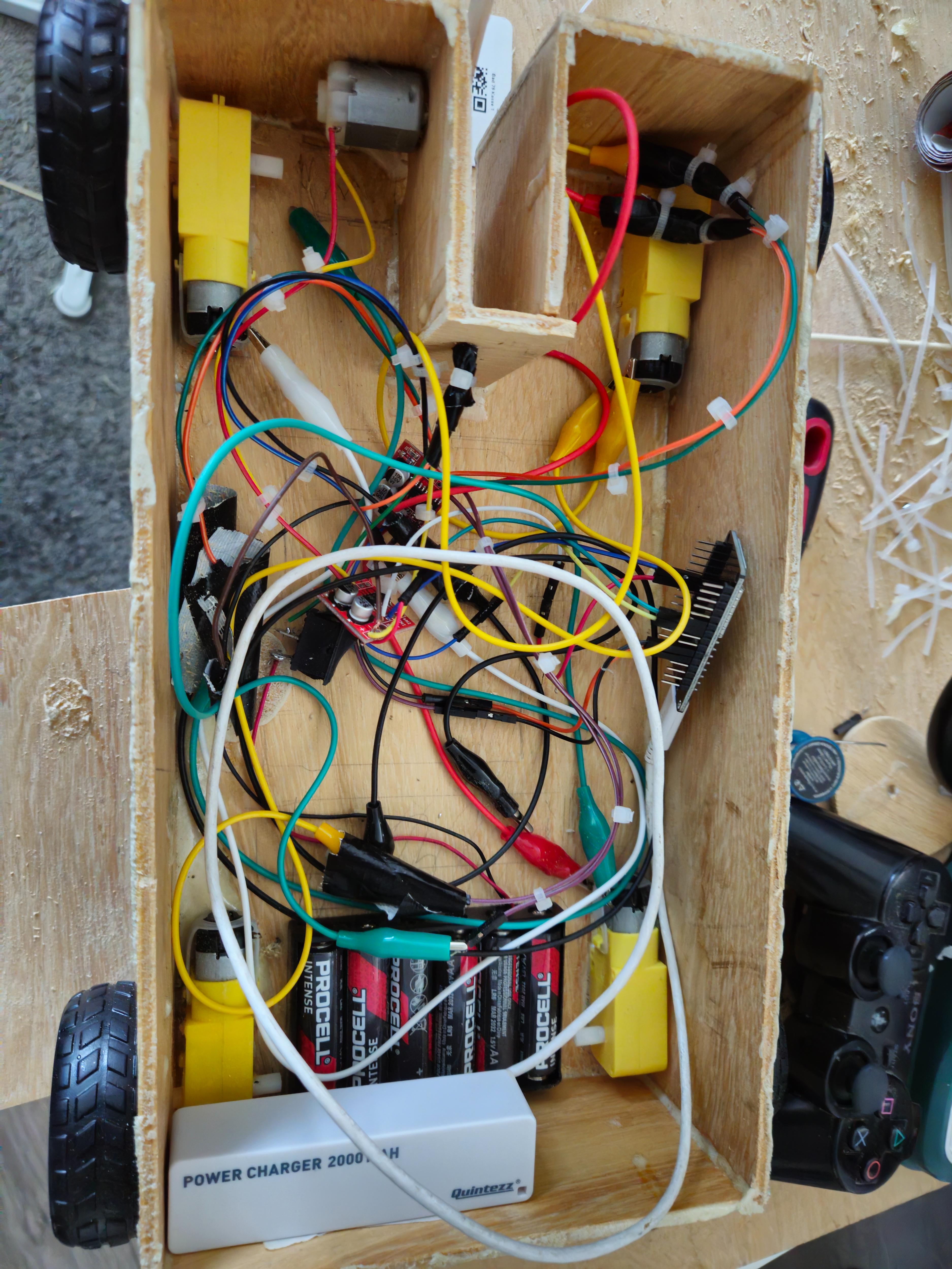
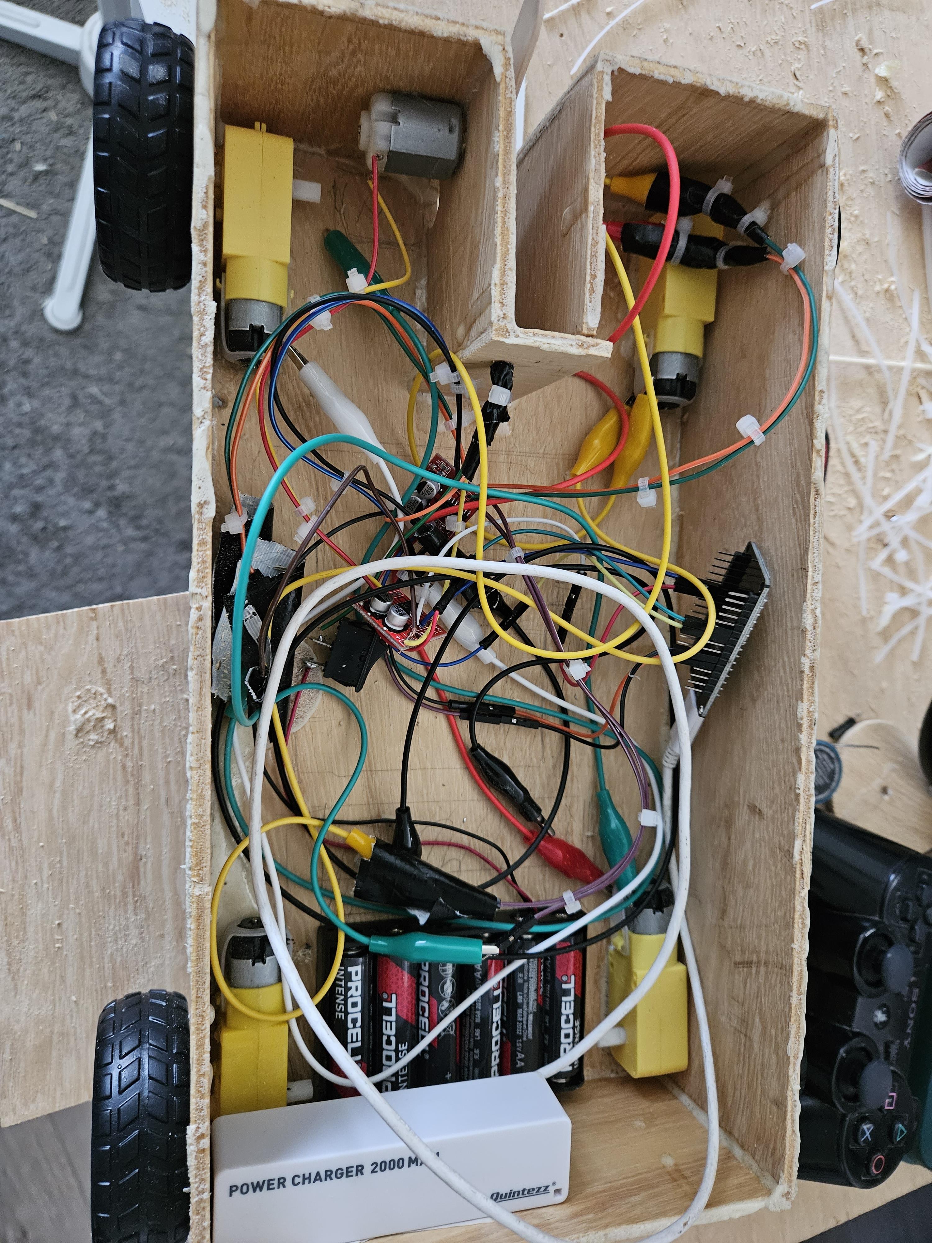
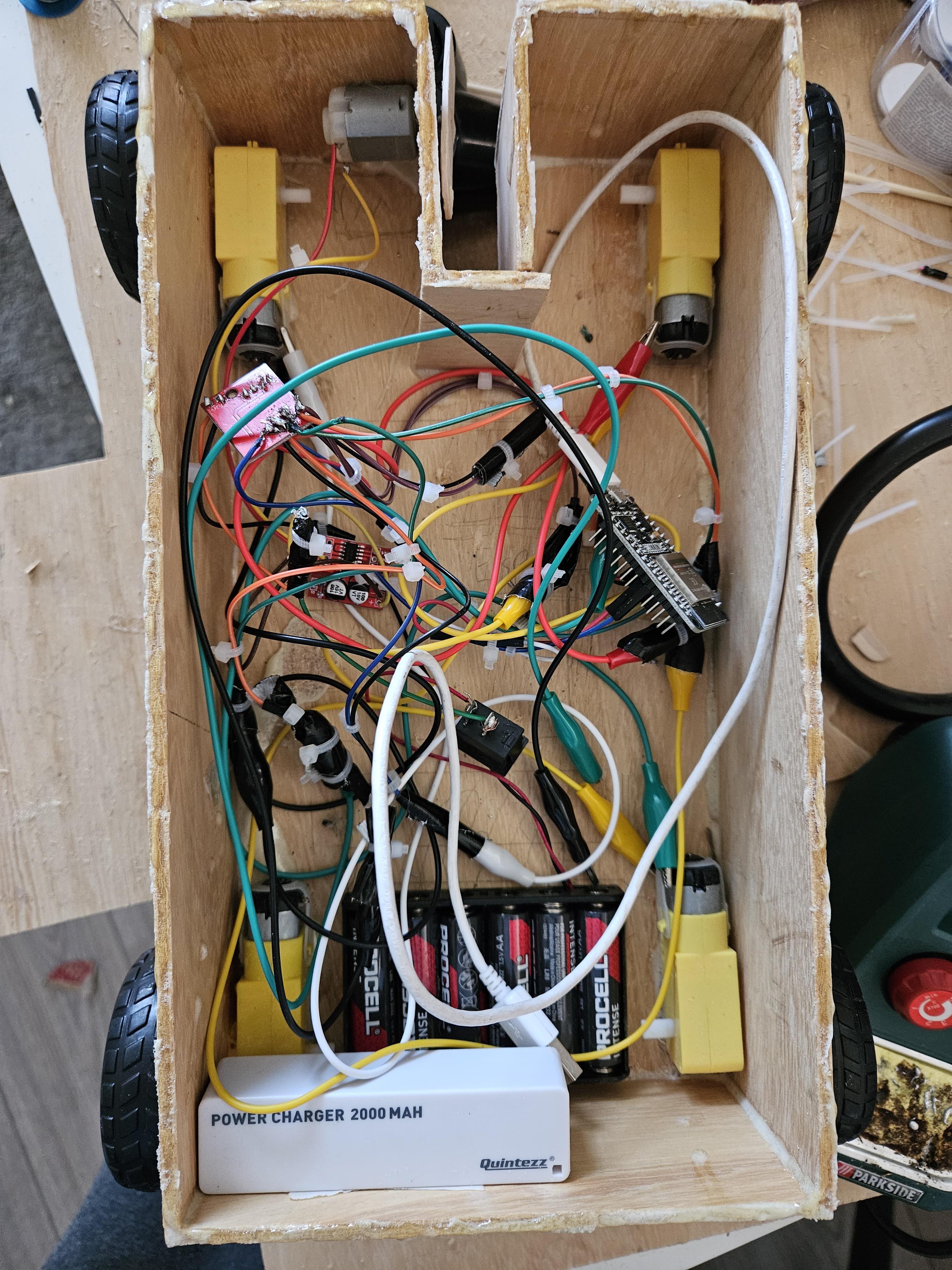
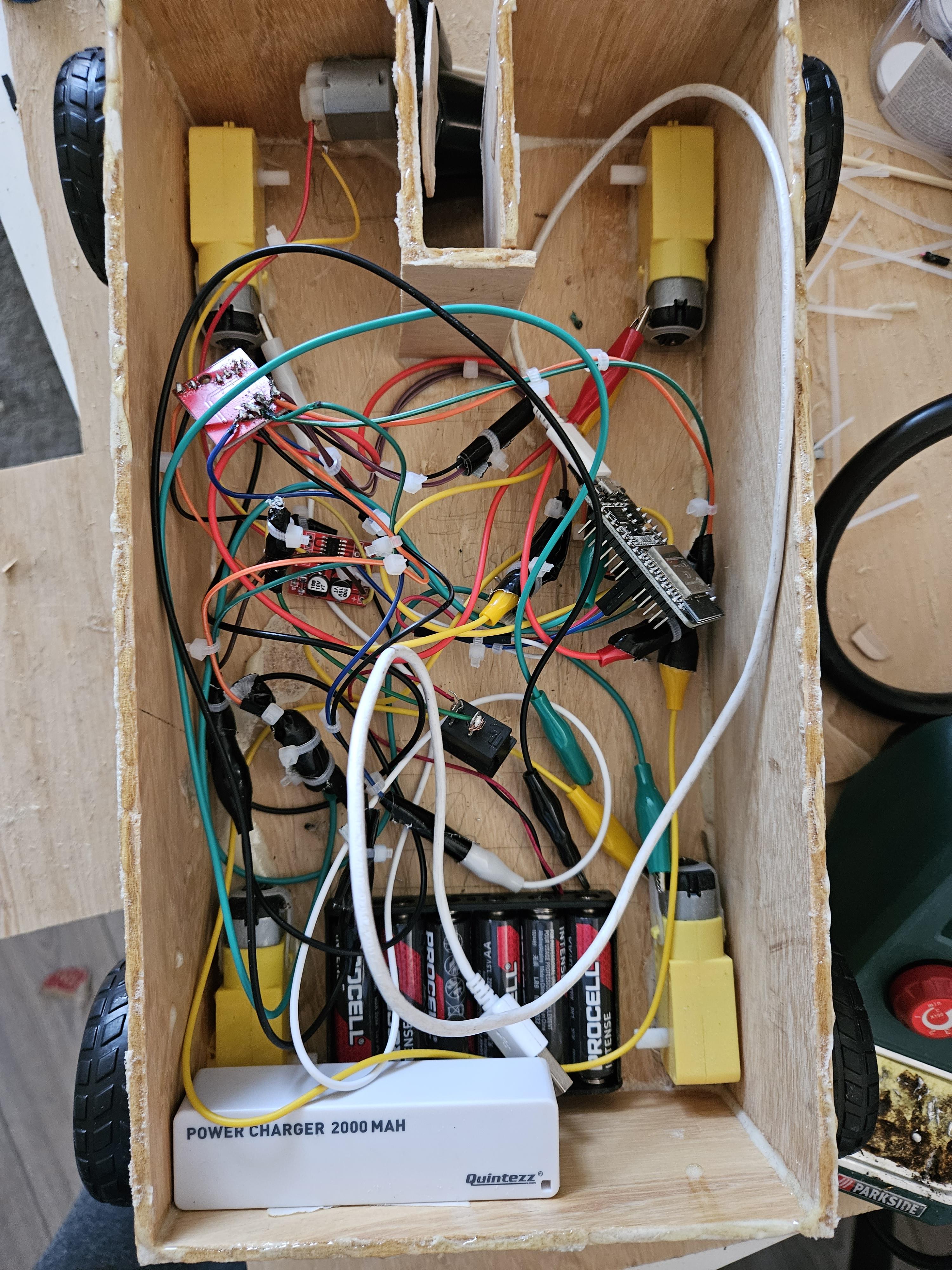
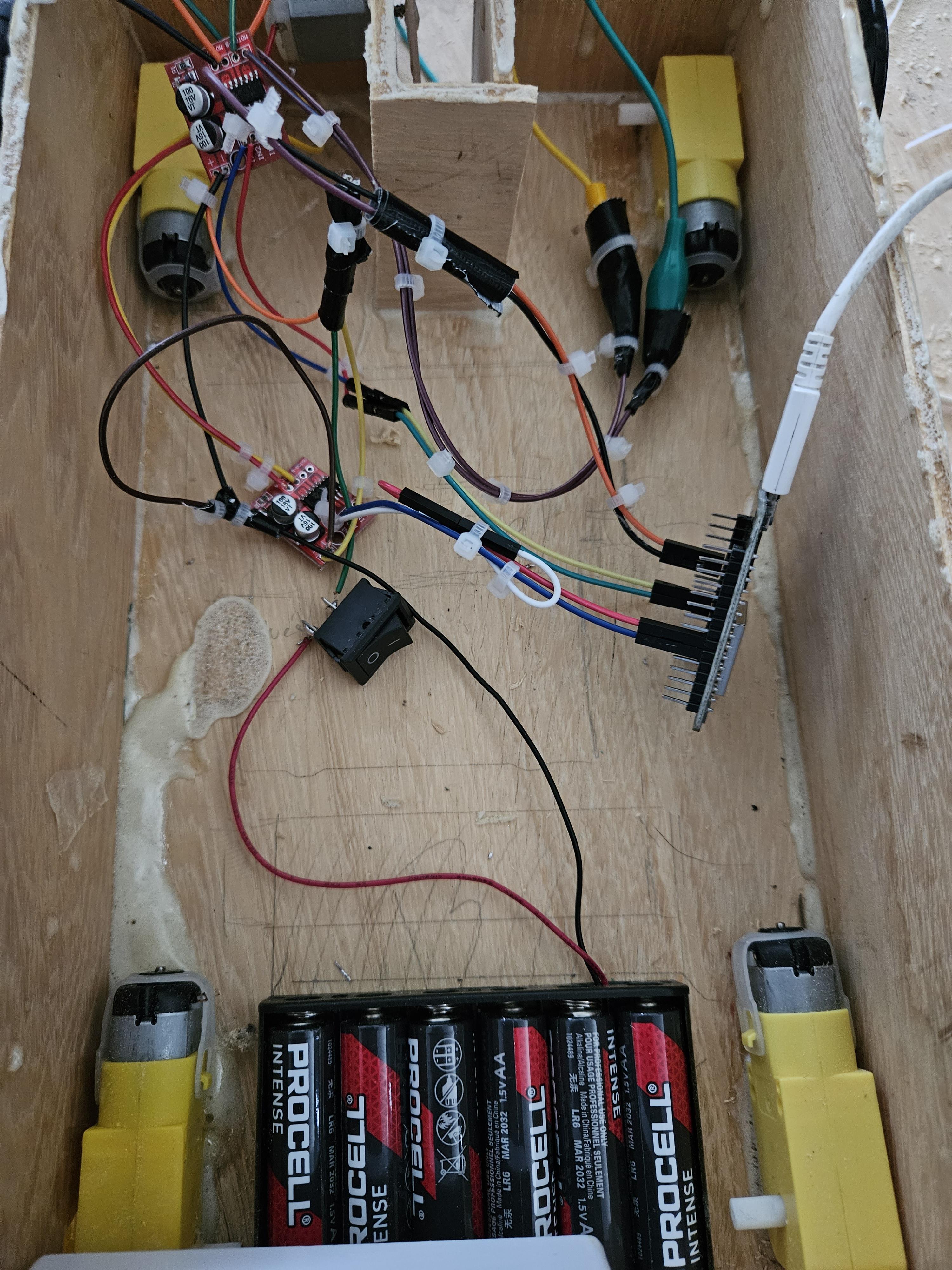
During the final step I put everything together, I glued the motors in place, stuck some double sided tape on the battery holder and powerbank to keep those in place as well, I made sure all of the wiring was correct and in place. After which I used some cable ties to make sure things didn't go loose and are somewhat managed in terms of cable management.
After everything was put together, I glued the top on and did some final gap filling and filing/rasping. Once the top was glued to the rest I placed a sheet of thick paper on top to cover the hole, while remaining access to it.
Reflection
There were a multitude of hiccups along the way, but even then, I enjoyed working on it.
Looking back at it there are certainly things I would have liked to do differently, like using a voltage converter for 3.3v and then connecting the esp32 to the battery pack as well, instead of having a separate powerbank. Leaving a bit more space for the wheels so that they aren't touching the wood, and planning in that regard. Although fully working, my soldering didn't look too great either, largely due to the small size of the motor driver, my lack of experience with soldering and the lack of a holder for it. But I did improve at soldering because of it.