Box Monster Updated
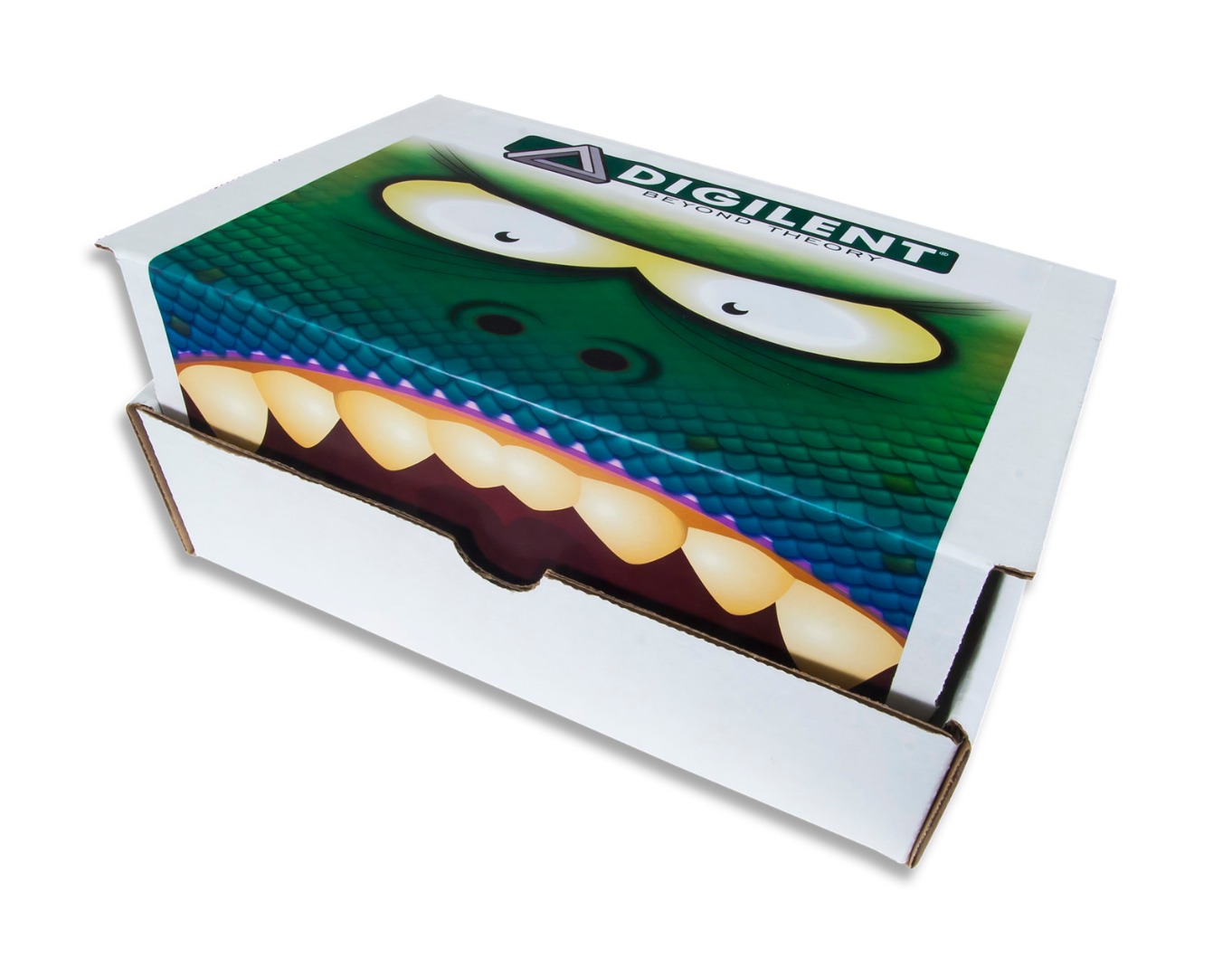
Hello again!
Some of you may have seen one of my previous I'bles that also happened to be on the Box Monster and are probably wondering how this one is different.
Well, as part of Digilent's K-12 initiative, we are wanting to revive the Box Monster and make it available for anybody (whether or not they are in the K-12 category) to use. Naturally though, it's best to have a set of instructions that match the materials that come with the box, so here we are!
Let's build a Box Monster!
What We Need
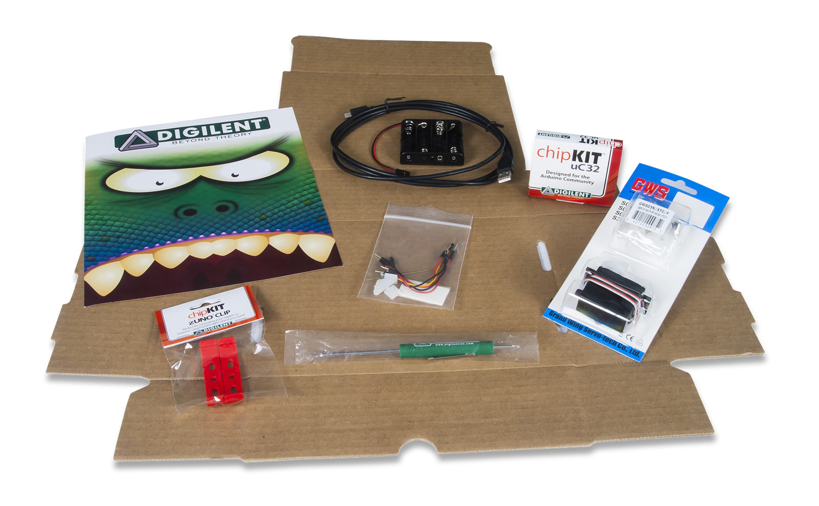
To start, let's make sure we have all of the materials that we need.
With the Box Monster, you will find:
- the Box Monster Box (Uline S-159 box)
- a scary Box Monster sticker
- a servo motor
- Digilent's chipKIT uC32
- a battery case
- a small bag with breadboard jumper wires, brass wire, and a servo horn
- Digilent screwdriver
You'll notice that some other things come with this kit as well such as some adhesive and other parts to attach to your servo motor; these are there to fuel your creativity with the Box Monster.
We'll also need a couple of other things on our own to make our lives a lot easier. This includes:
- Hot glue gun (and some hot glue)
- a ruler
- small pair of needle-nose pliers
- 4 AA batteries
Let's get started!
Getting Started - Prepping the Box
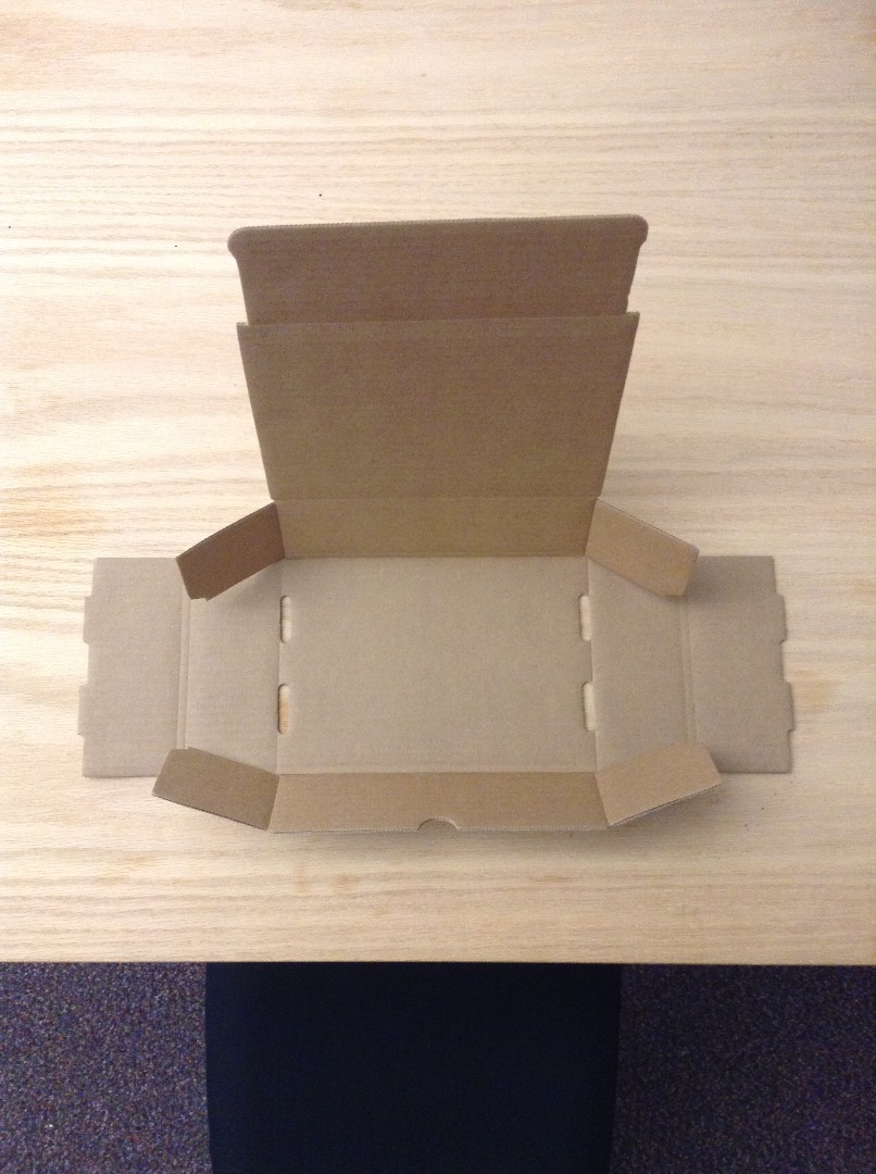
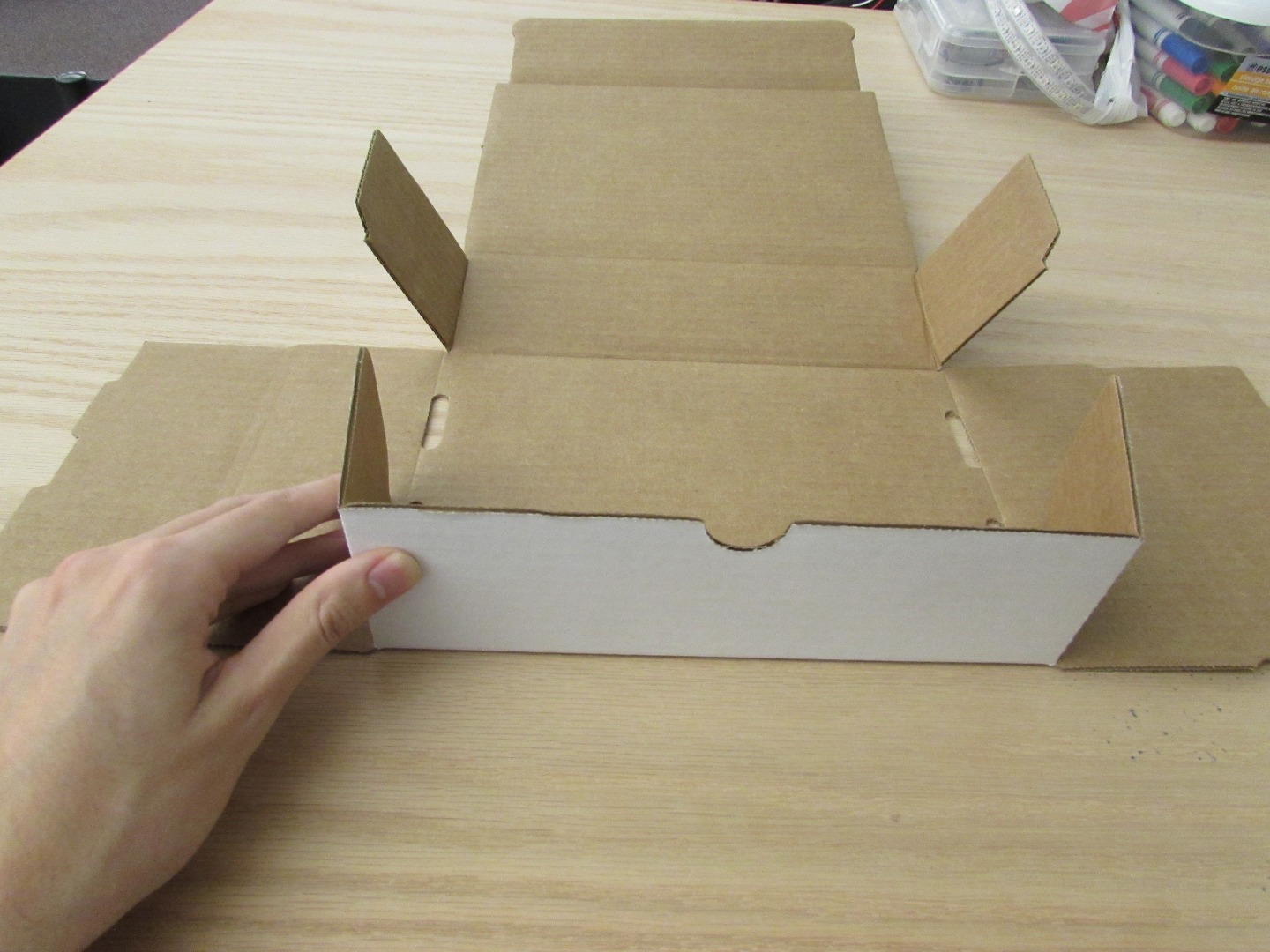
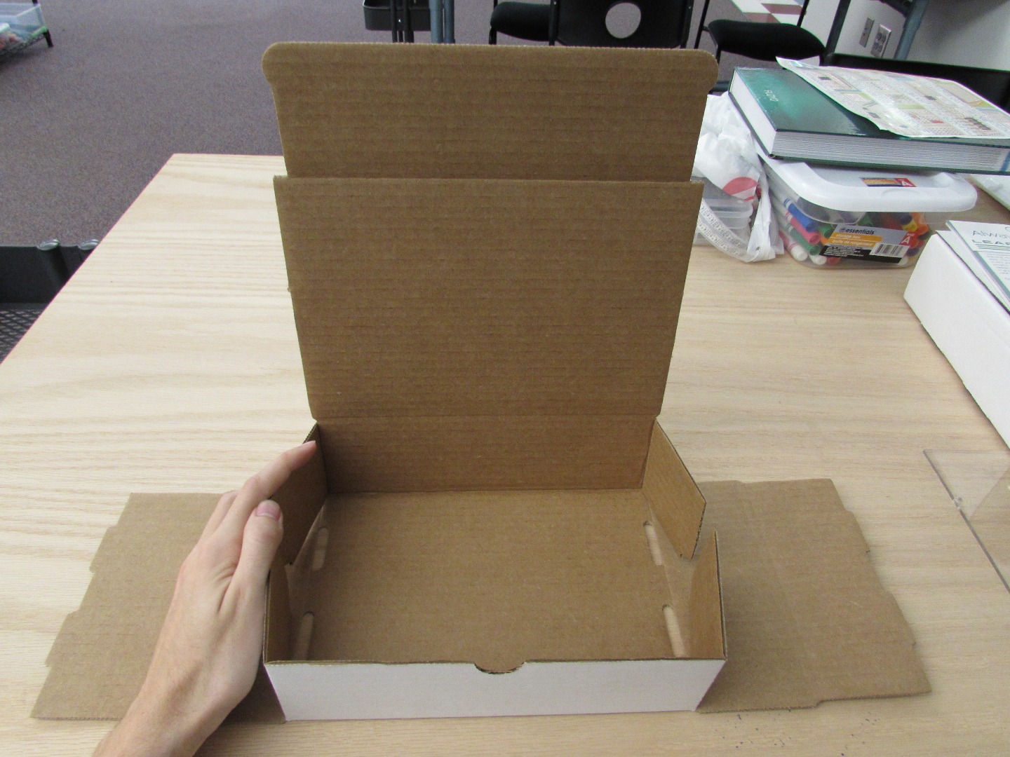
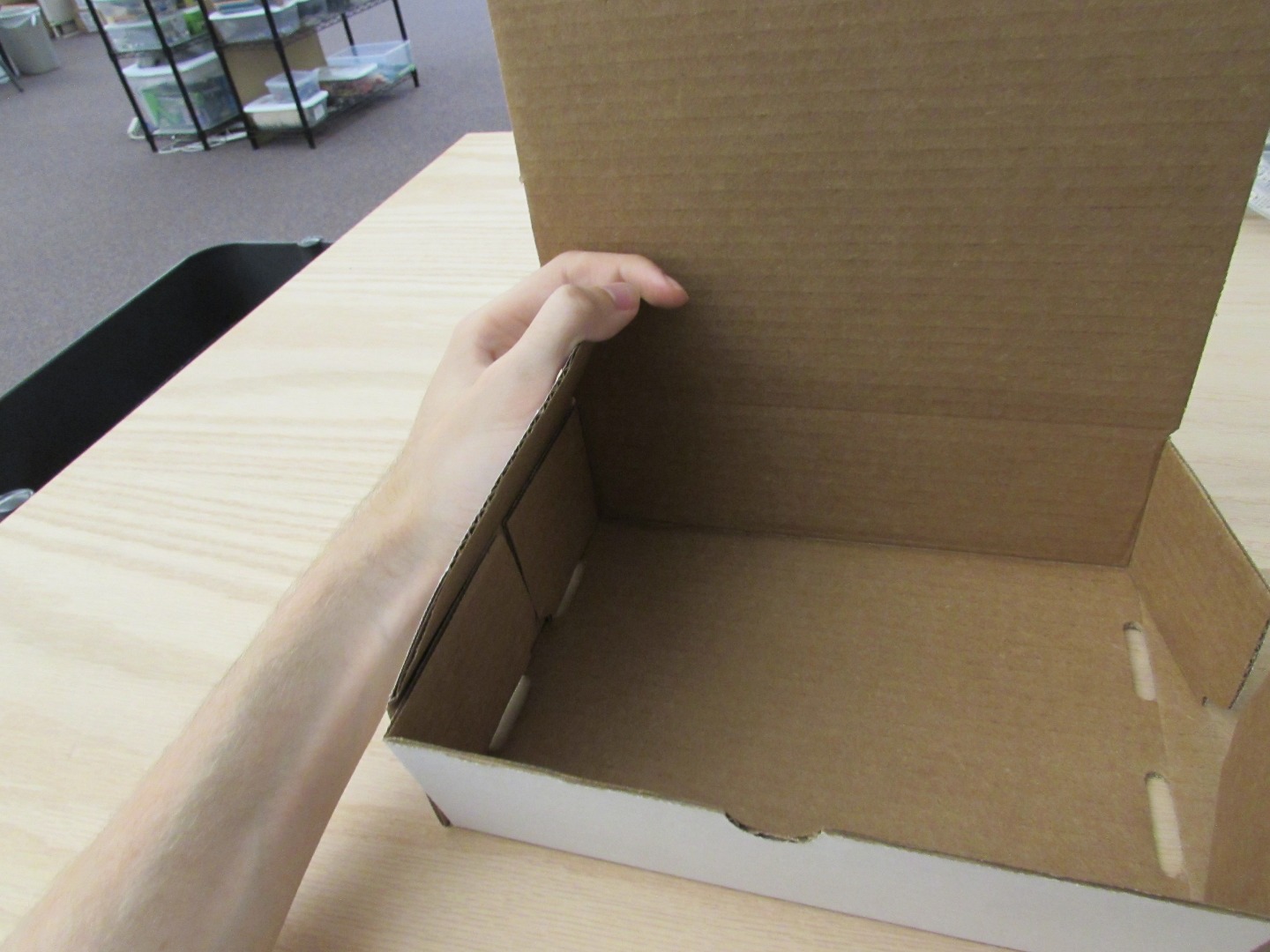
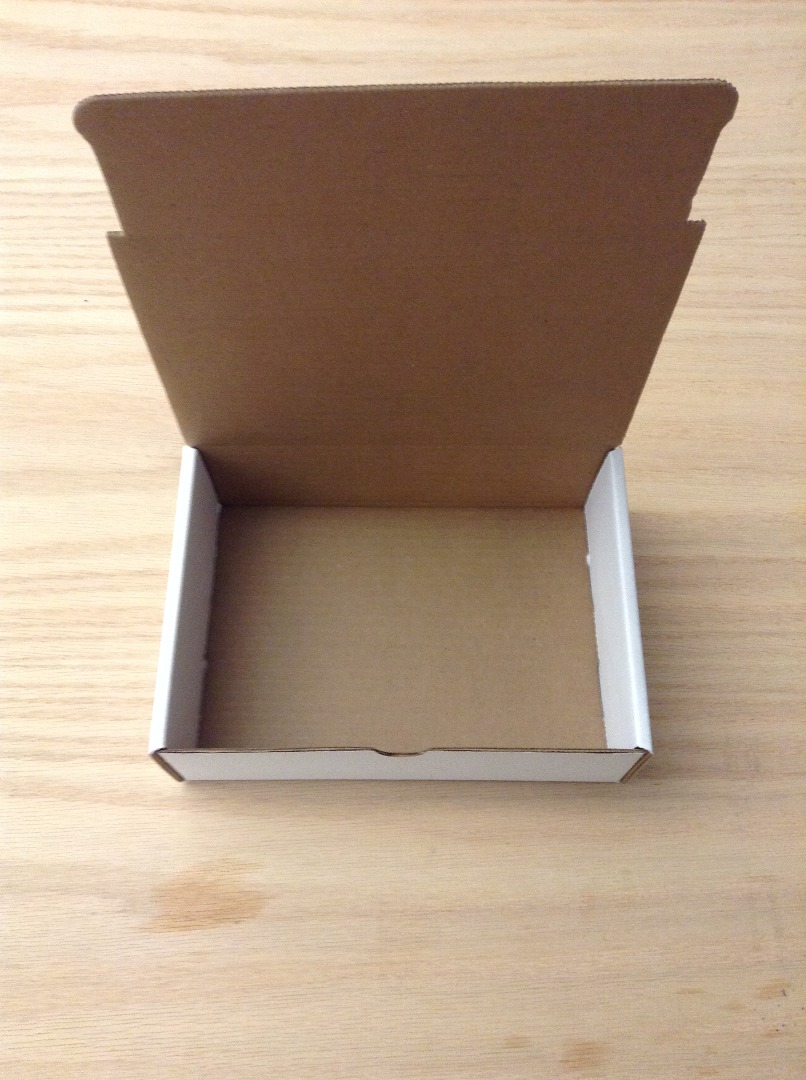
Once we have all of our materials at hand, let's start by getting the box folded into the shape we need.
First, with the box laying flat (brown side up), fold the tabs of the bottom and top portions of the box inward as you see in the first picture.
Then, fold the bottom and top of the box upwards like you see in pictures 2 and 3.
You will then be able to fold the sides over the top of the tabs (picture 4) so that you have a complete box (picture 5).
Prepping the Wire Hook
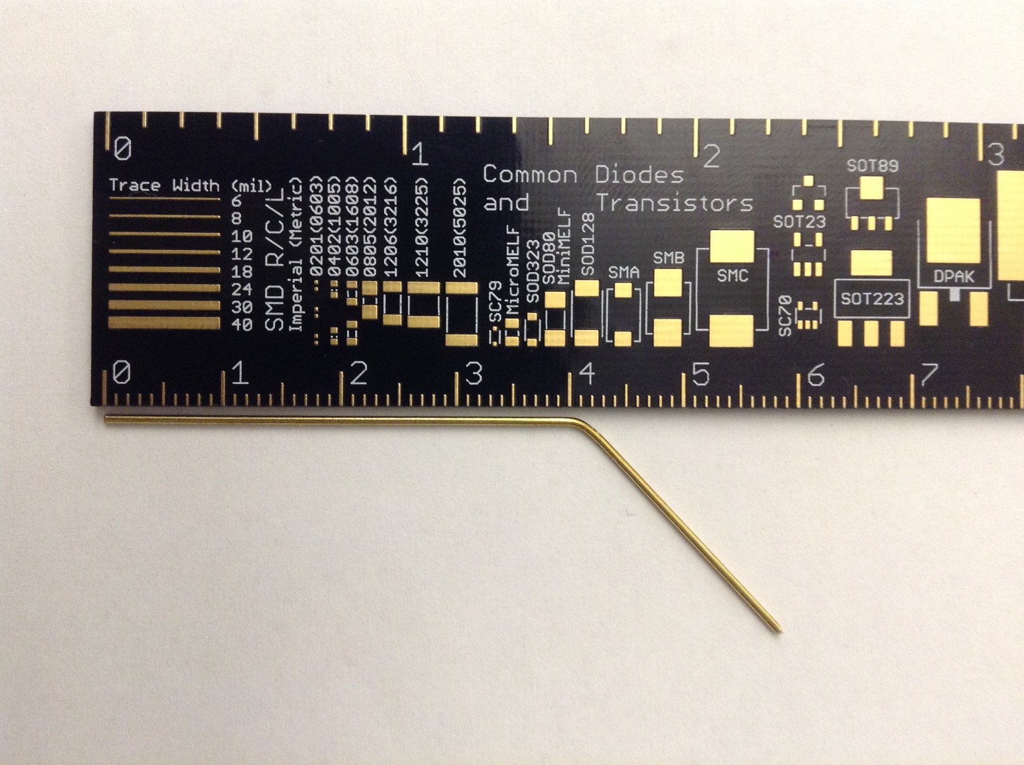
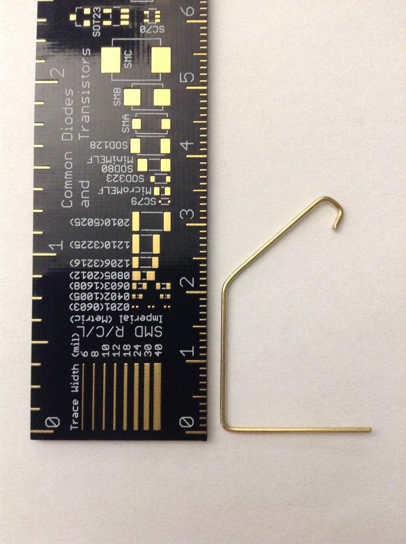
Now that we've gotten most of the box done, grab a ruler and the piece of brass wire that came with the Box Monster kit.
The brass wire will be about 63 mm long; it may be a little longer or a little shorter, but as long as it is between 58 and 68 mm, it'll work just fine.
First, make an approximate 45 degree bend in the wire about 42 mm from one end (or 41 or 43 mm). The angle itself does not need to be super accurate; as long as you can say that the bend is at "basically the same angle", that's good enough. See picture 1 for a reference.
Then, make a 90 degree bend about 21 mm (halfway-ish) between the bend you originally made and the end that is farther away. On the end of the 45 degree angle end of the wire, make a small hook with a pair of pliers (or something similar). Again, the 90 degree bend isn't super important; we'll actually be bending it even more later on so that it stays attached to the servo horn, but we'll wait until then to do so. Check out picture 2 (next to Adafruit's sweet PCB ruler) for a visual reference of how your wire should look afterwards.
Prepping the Servo Motor and Servo Horn
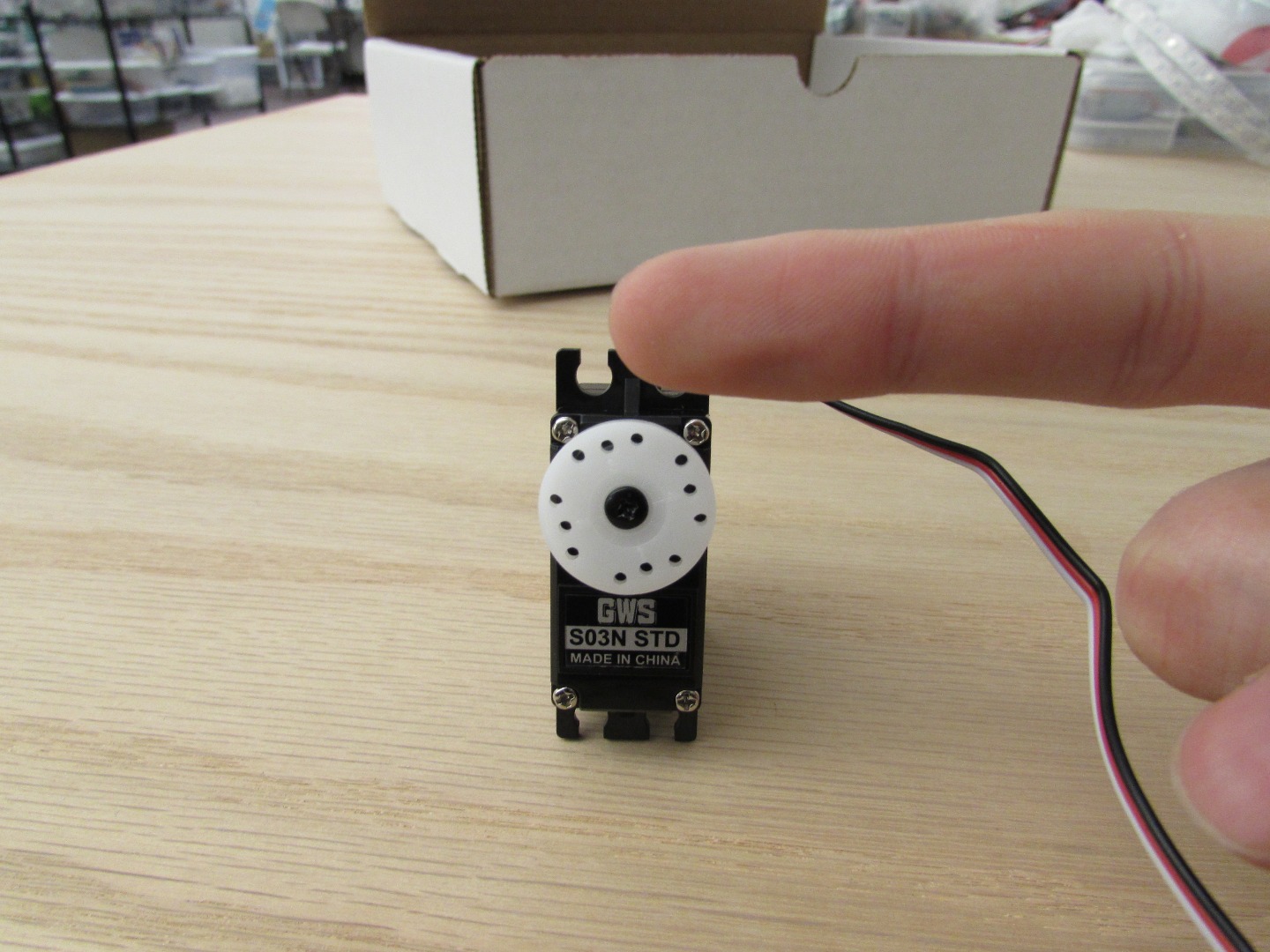
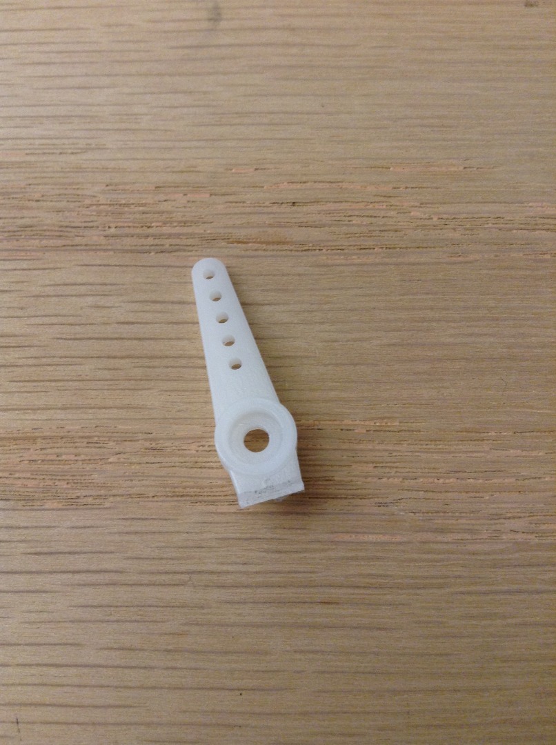
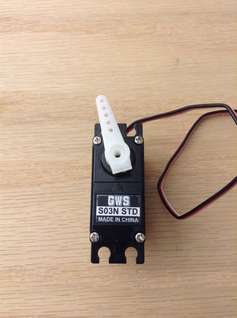
Great! Let's move on to getting the servo motor physically ready to go.
First we want to rotate our servo motor all the way to the left (counter-clockwise) with the letters oriented in the normal reading position and the wire set coming vertically up out of the motor, much like you see in picture 1. I personally recommend unscrewing the circular piece that comes on the servo motor and putting on of the "armed" pieces to rotate the motor much more easily.
Once you have gotten the motor rotated, take the two armed piece and break off one of the arms. We're doing this so that when the servo motor is opening and closing the mouth of the Box Monster, the other arm isn't hitting the side of the box. Attach the piece at a slight angle away from vertical to the motor spindle; this angle is to help ensure the code causes the Box Monster to open and close correctly.
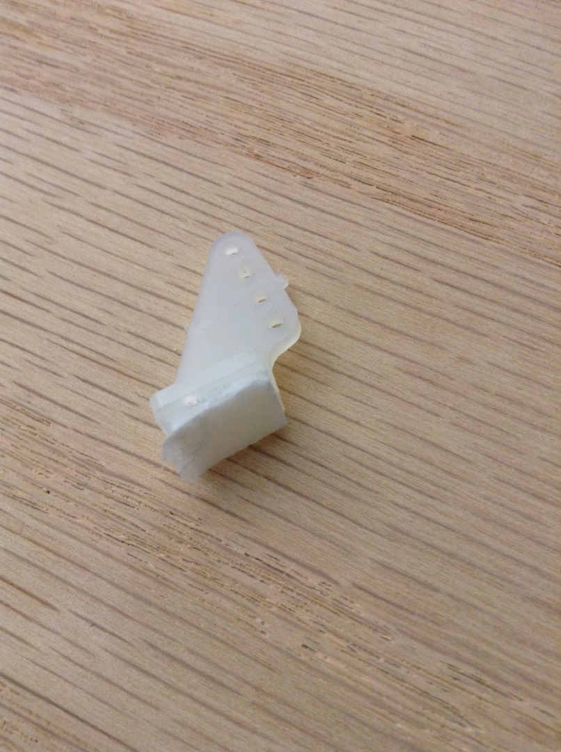
The servo horn prepping is pretty straight forward, simply break off the weird square thing (not the base) that is attached to the triangular portion of the servo horn (picture 4).
Putting the Servo Motor and Horn in Place
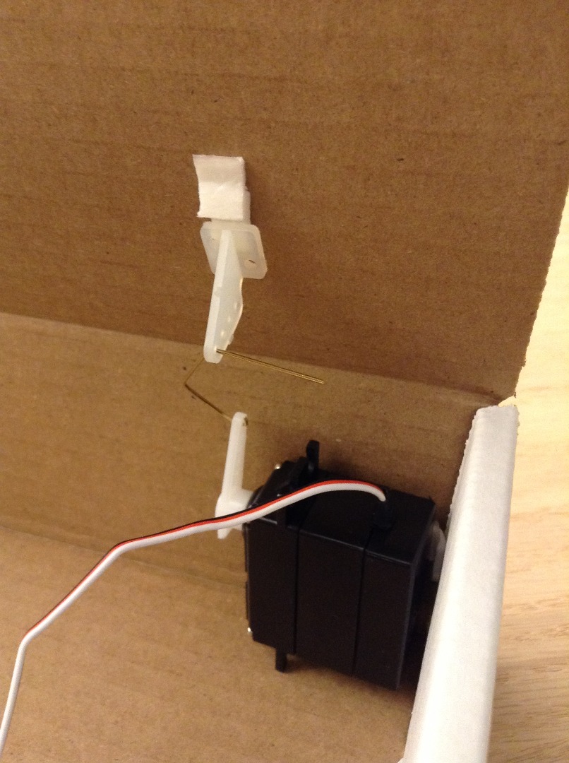
Let's get the two servo components in place.
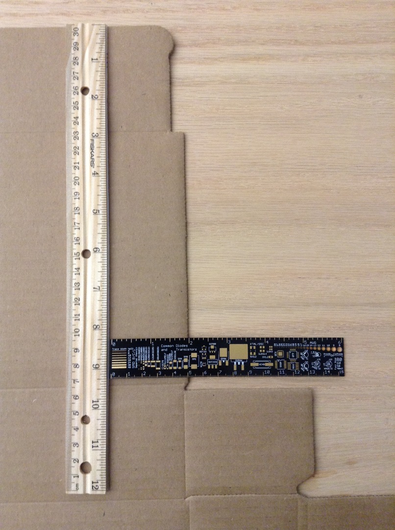
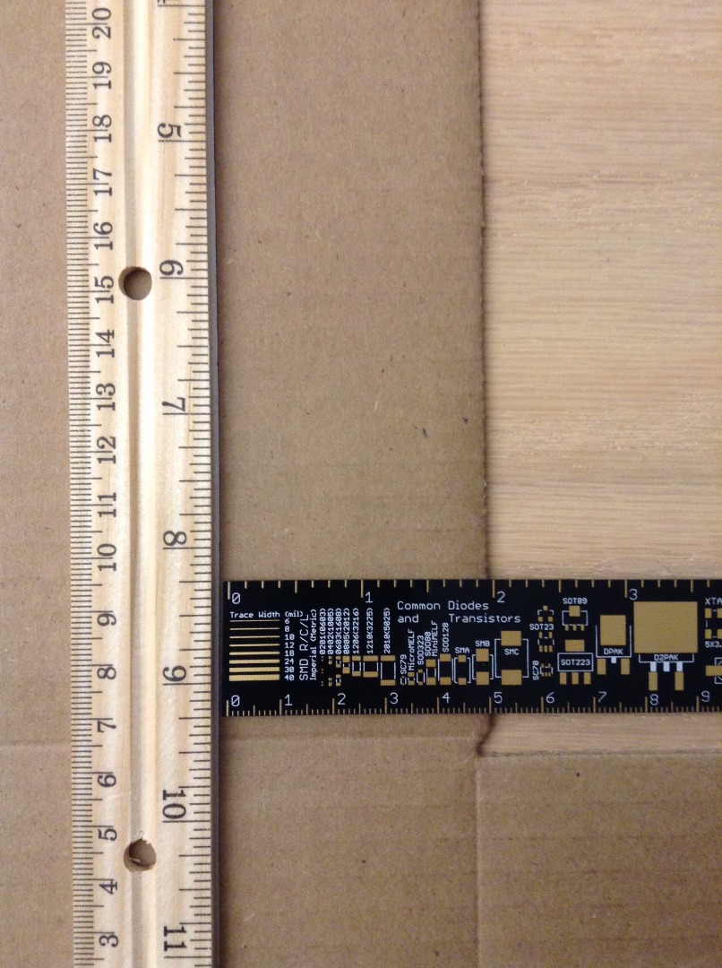
The servo horn will go on the "ceiling" or the "roof of the mouth" of the Box Monster. Taking the length of wire that we have available into consideration, I have found it best to center the servo horn 8.25" from the top of the box and 2" from the right of the box lid, as shown in pictures 1 and 2. You may find a slightly better location for yourself, but this has worked great for me. Make sure to have your servo horn angled downward when you attach it to the roof of the Box Monsters mouth to avoid having to re-bend the wire.
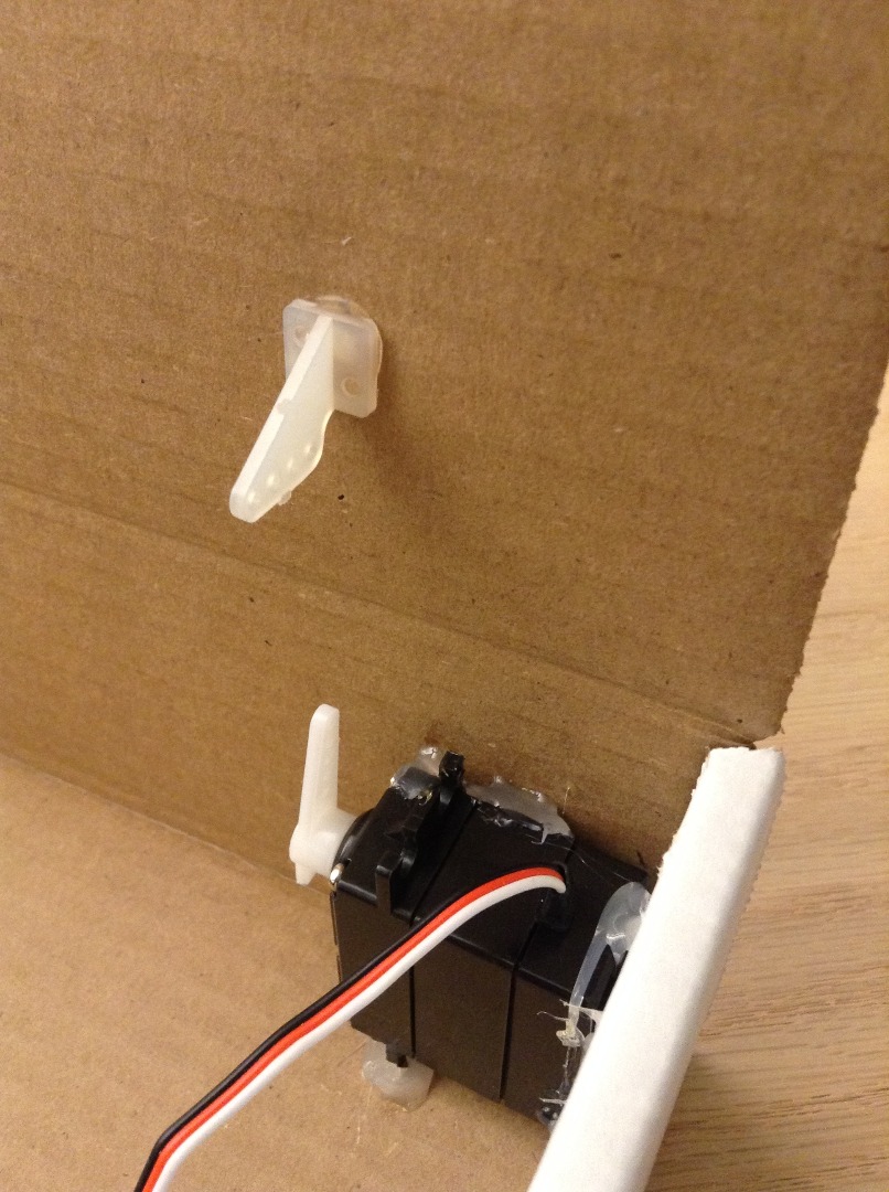
The servo motor itself will be placed in the back left corner with the servo arm pointing upwards. You can use some of the one-sided tape to hold it in place, but I'd recommend using hot glue as a more permanent solution to keep the servo motor there. See picture 3 for a visual reference.
Once the two servo motor components are in place (with the servo arm facing upward), attach the hook on the brass wire to the hole farthest away from the center of the servo arm and thread the other end of the wire through the farthest hole from the base. If you're happy with the wire there, feel free to bend the portion of the wire sticking out of the servo horn downward so that it doesn't accidentally slip out while the motor is running.
Getting the Monster on the Box
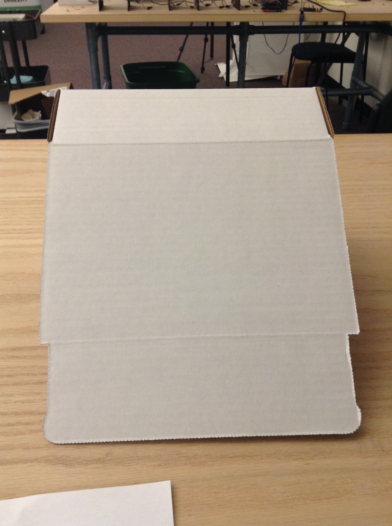

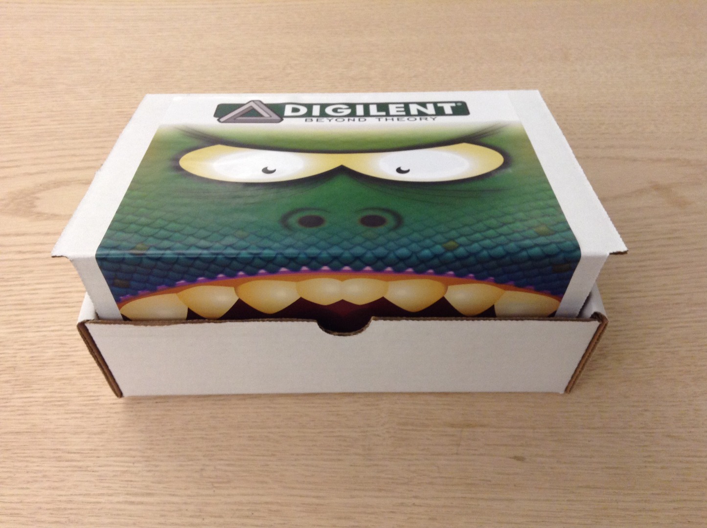
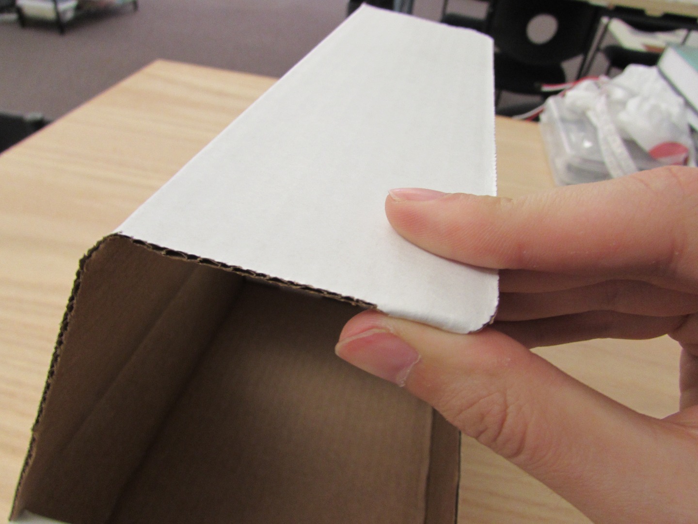
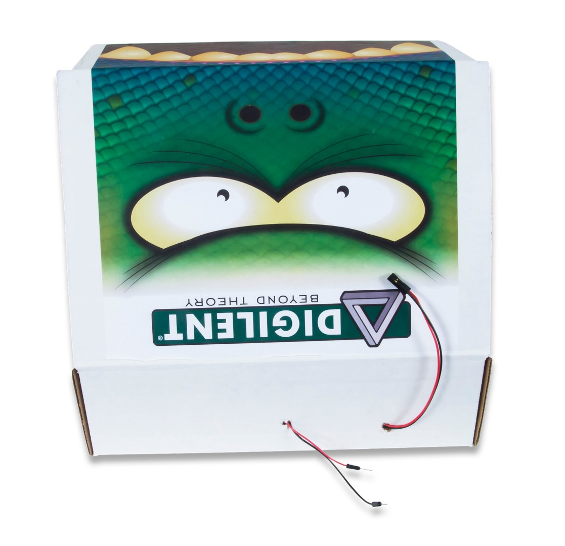
This step simply involves putting the monster sticker onto the box which is usually pretty self-explanatory, but we'll cover it anyway.
I recommend rotating the folded box so that it sits on the table like a tent with the lid facing towards you (picture 1). The sticker will be placed on the lid with the mouth of the monster on the top tab portion (picture 2) so that when the box is completely folded, it looks like the monster has its mouth closed (picture 3).
To get Box Monster to effectively open and close its mouth without putting too much strain on the motor, I would fold in the tabs on the side of the lid so that the mouth portion of the box (picture 4) so that there is not too much resistance when the lid is opening and closing.
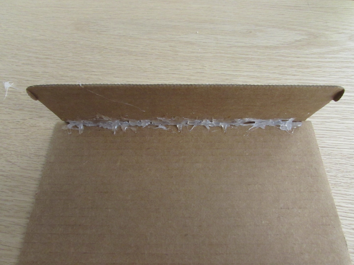
It is also helpful to put a line of hot glue along the inside edge of the mouth with the lid bent in slightly so that when the Box Monster is closing it's mouth, it doesn't bounce off the very front of the box. See picture 5 for a visual reference.
Getting It All Together - Part 1
But before we get to run off with our new Box Monster, we have to get the microcontroller board and the batteries ready to go.
First, we need to get the appropriate code put onto our microcontroller board. Thankfully, this is very easy to do.
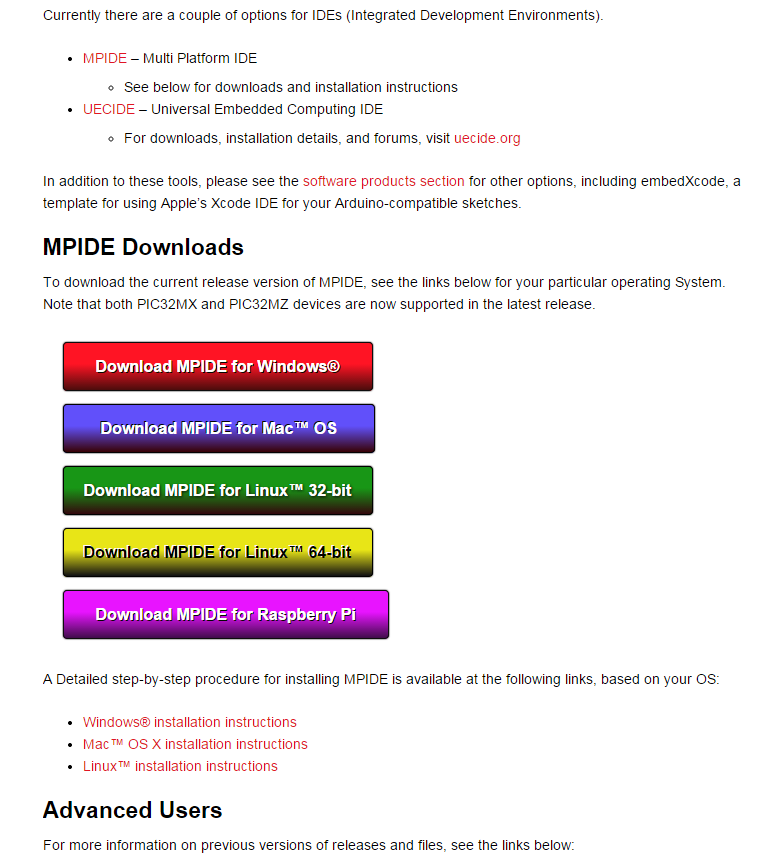
Download MPIDE (the free software that we will use to program the chipKIT uC32) for your appropriate operating system from here. Check out picture 1 if you're not sure where to click.
Once it's downloaded, open up the zip file of the Box Monster code at the bottom of this step, or open up a blank MPIDE sketch and copy and paste the text file (also at the bottom of this step) into the sketch. If you're not sure how to do this, there's a great tutorial that shows you step by here.
Attach your chipKIT uC32 to your computer by using the USB A to mini B cable and upload the code onto your system board. That same tutorial that I mentioned in the above paragraph explains how to do that starting in Step 3.
Once your board has successfully gotten the code uploaded to it, feel free to unplug from your computer and move onto the next step in this I'ble.
Getting It All Together
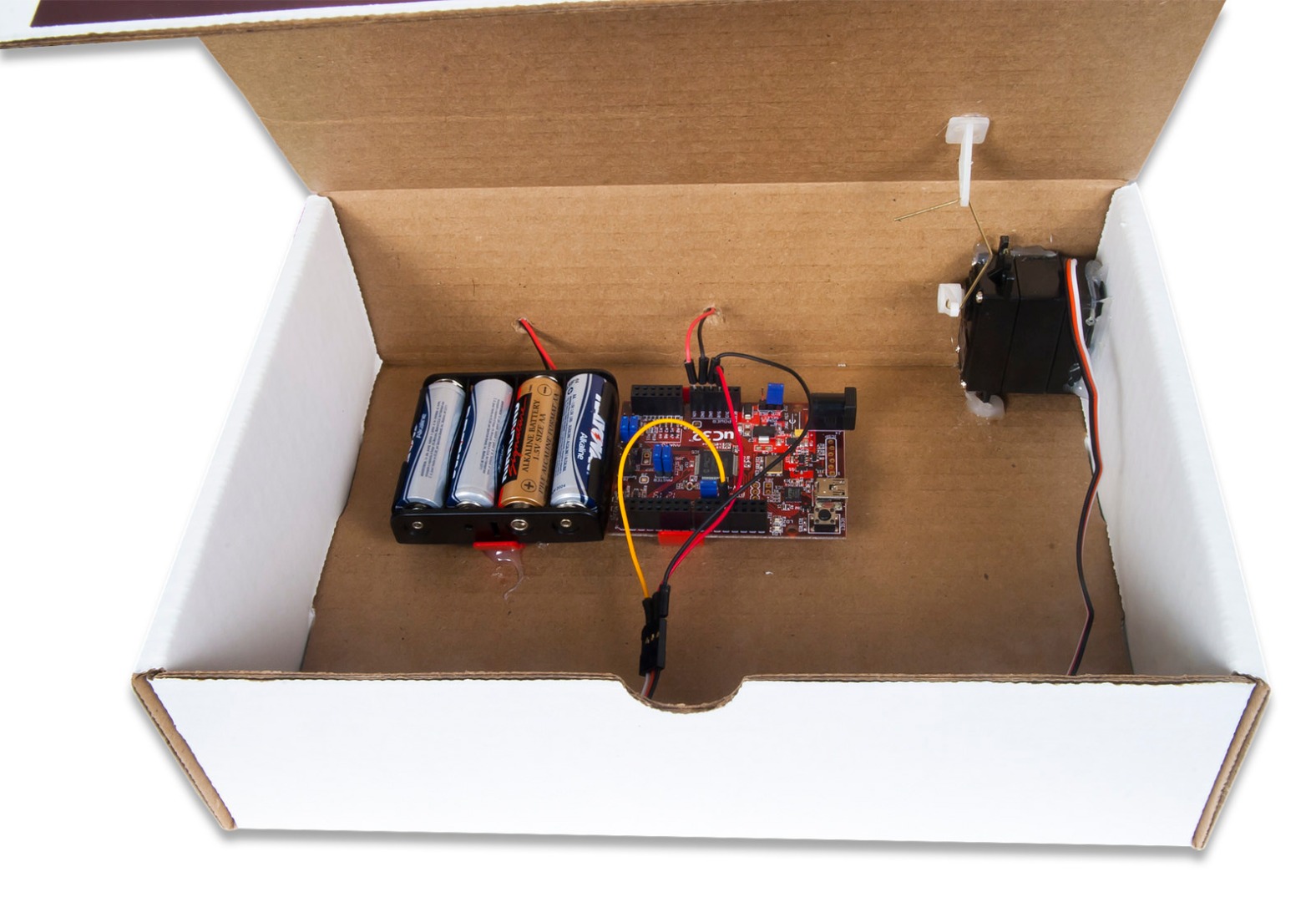
Now that we have the code ready, poke two small holes in the back of the Box Monster with the screwdriver, a pen, or anything else you find convenient to use, much like the holes you see in picture 1. This is for the pair of power and ground cables coming from the chipKIT board and the battery holder so that they can be easily connected and disconnected without having to reach inside the Box Monster's mouth.
Put a zUNO clip on both the chipKIT uC32 and the battery holder. It may be a little difficult to get the clip onto the battery holder, so its not necessary for the battery holder. You will want it on the microcontroller board though so that if you ever want to take it out of the box, you won't have to worry about getting any glue off of it.
Once the clips are in place, use your hot glue (regular glue, tape, etc) to secure the battery holder on the left hand side of the box with the 2-pin cable on the side closest to the hole on the left and secure the chipKIT board to the right of it with the pin headers labeled "Power" and "Analog" closest to the back of the box.
Take one of the black jumper wires (or any color, but I prefer black for color coordination purposes) and attach it to one of the "Power" pins labeled as "GND" on the uC32; either one will work great. Then take a red wire (again, for color coordination) and plug it into the pin labeled "VIN" on the "Power" section of the uC32. Poke both of these wires through the hole in the back of the box as well as poking the two wires coming from the battery holder through the other hole in the back of the box. You'll end up seeing something very similar to picture 2. Whenever we want to get our Box Monster up and running (presuming we have batteries in place), we will connect the red cables and black cables together, respectively.
To wire up our servo motor, attach a red jumper wire between the pin labeled "5V" in the "Power" section and the red wire coming out of the servo motor. Then, attach a black jumper wire between the other pin labeled "GND" in the "Power" section and the black wire on the servo motor. This will provide the necessary power for our motor. The white wire coming out of the servo motor is the data line and should be attached to digital pin 11 on the chipKIT uC32. Check out picture 1 for a visual reference.
Final Thoughts
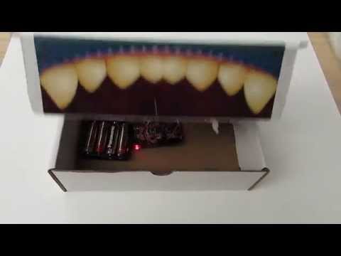
We have now finished building our Box Monster! Plug in your 4 AA batteries and connect the cables in the back of the Box Monster to start running the routine that we loaded onto the chipKIT board. You are welcome to modify the code to get the Box Monster opening and closing it's mouth in a different pattern, or have the microcontroller do something else entirely.
You can check out our video of the Box Monster in action in our YouTube video. You'll notice that the internal design is a little bit different, but the principle of building and coding it is the same.
The Box Monster Kit is coming soon, so keep checking for it at digilentinc.com/BoxMonster or post a question on our Forum.
Please feel free to ask any question or leave a comment in the comments below!