Bluetooth Police Beacon
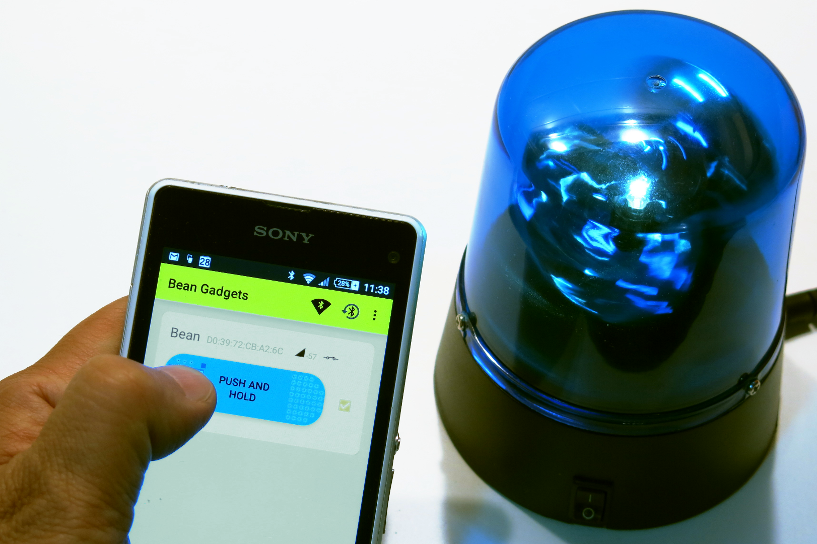
This mini rotating police beacon can be turned on and off remotely, from a smartphone via Bluetooth Low Energy (BLE).
In this project, we will get hands-on experience on:
a) Using a Lightblue Bean (old version) -- a small Arduino compatible board, dedicated to BLE.
b) Converting a 5V power supply to 3.3V.
c) Driving a load, using a MOSFET.
d) Creating an Android app with the Bean SDK, using the smartphone BLE capability.
e) Programming a simple Arduino sketch into the Bean.
Notes
- The "beacon" mentioned here has nothing to do with Bluetooth beacons (iBeacon). It is just, really, a rotating light.
- The Bean, with added circuitry, its firmware and sketch, the smartphone, its OS, Bluetooth stack, and the app... all of these, together, are playing the role of a simple wire with a push button at the end. Aren't we living in a wonderful era?
- If you find this project cool, please vote for it!
But... Why the Hell Should I Have a Bluetooth Low Energy Mini Police Rotating Beacon?
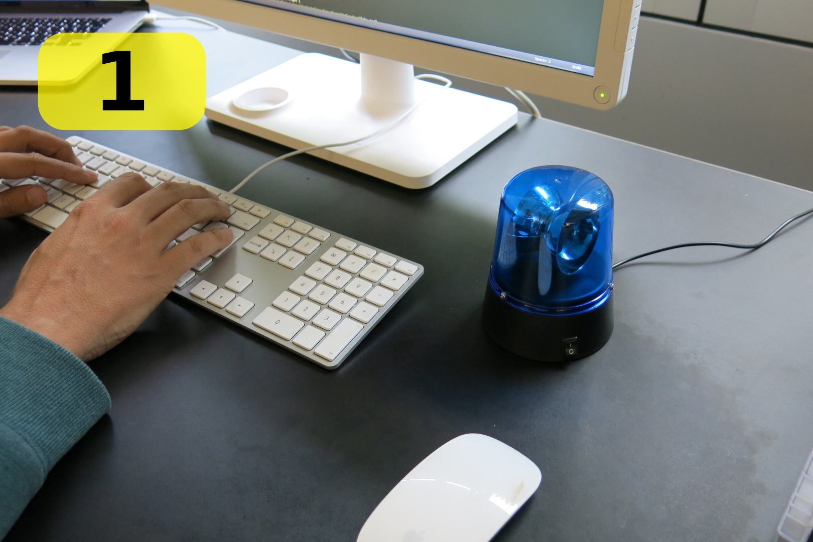
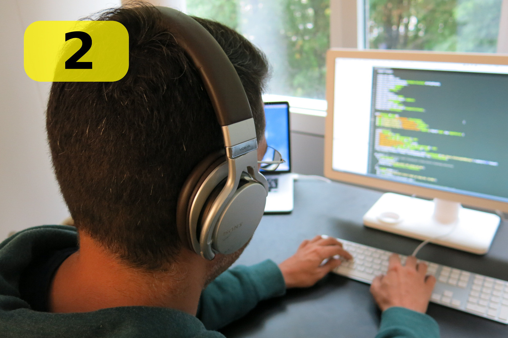
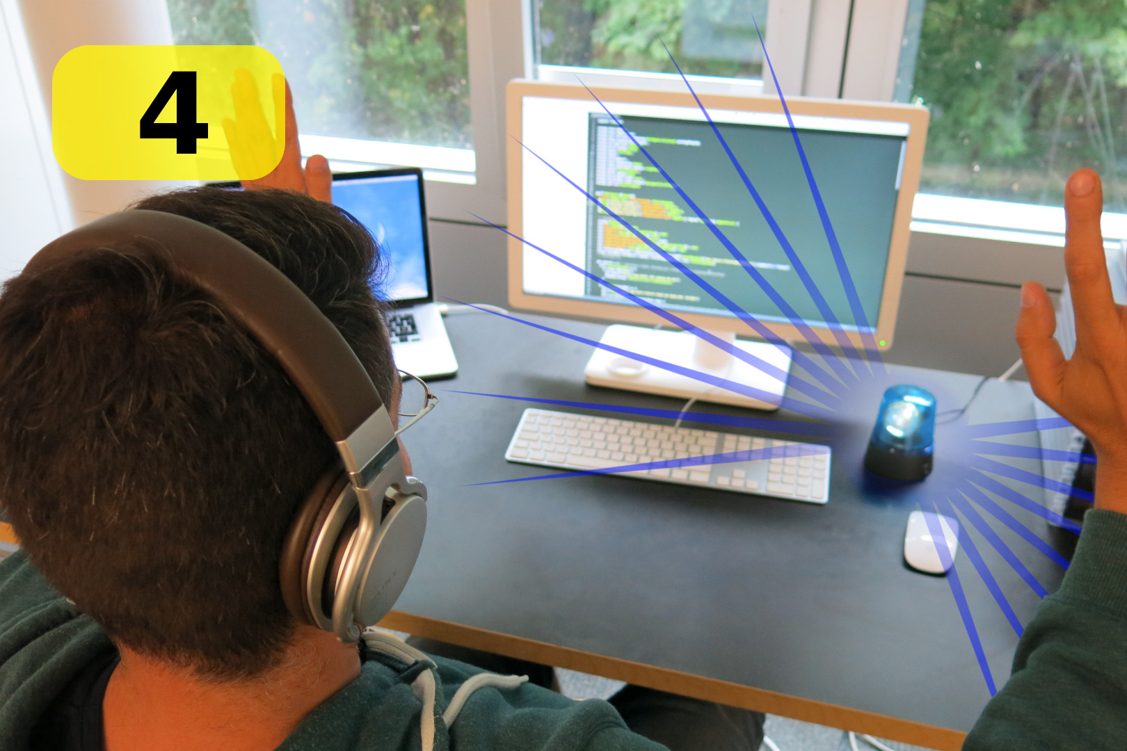
Your startup co-worker, like many software developers, wears headphones when in deep mental concentration. Which is also a strong "don't disturb" statement.
Sometimes you really, really, really need him/her. This beacon brings a visual signal, with coolness.
Usage steps:
1. Install beacon on co-worker's desk
2. Co-worker is in intense concentration (*)
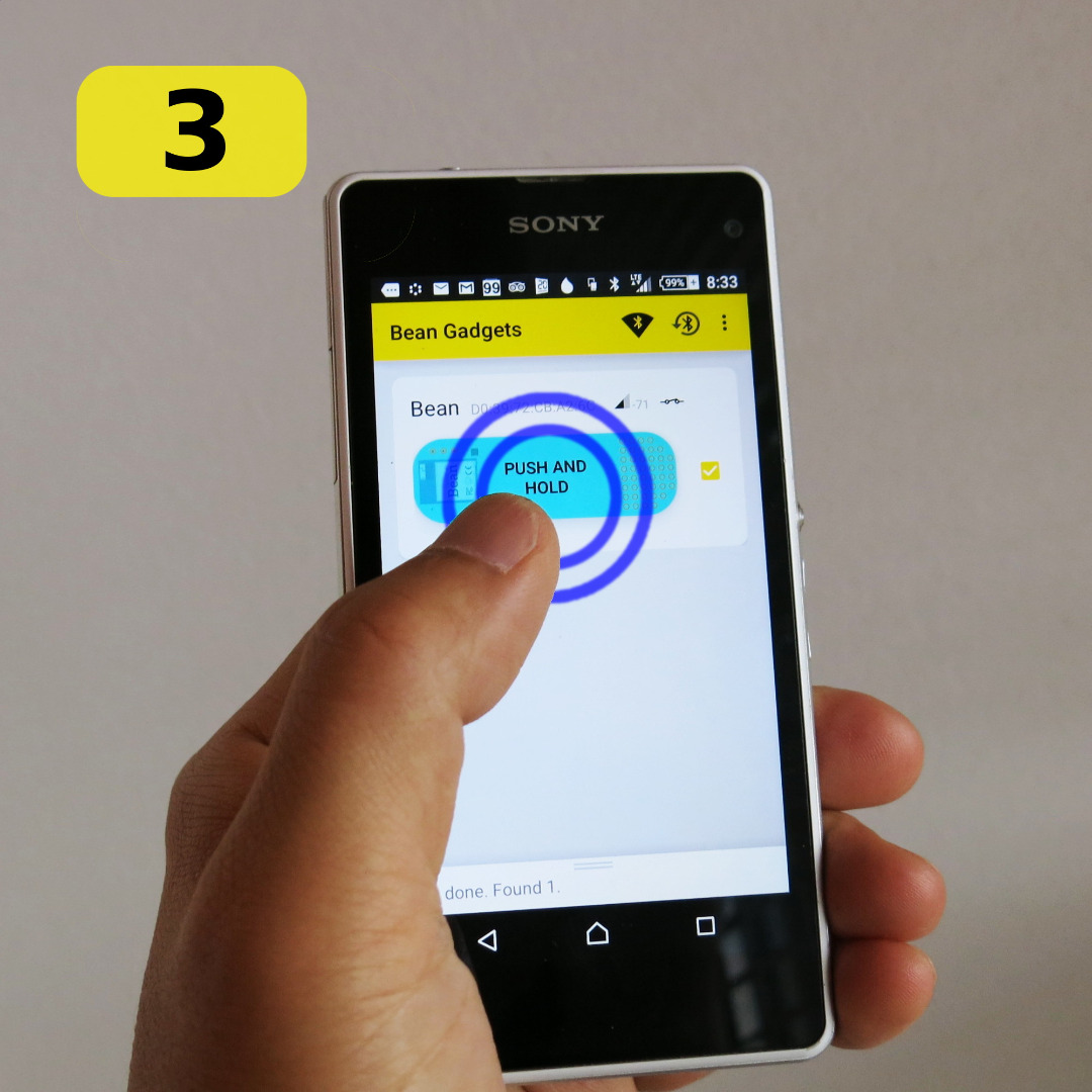
3. To attract attention, push the button on your phone
4. Co-worker's attention is caught !
(*) Hoodie + headphones + concentration + Scala code... = must be a real programmer!
How It Works
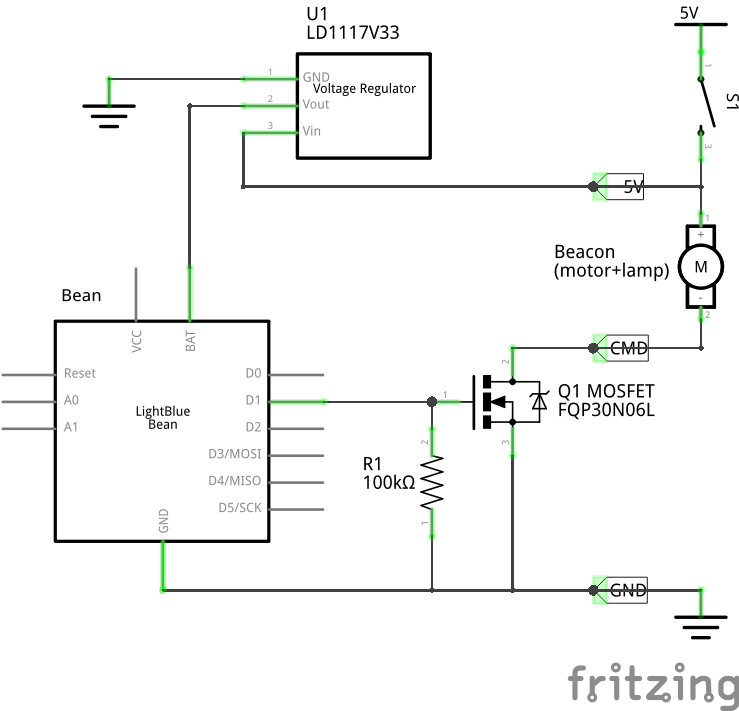
As shown in the above system diagram, there are three principal aspects:
Power
5V is taken from the beacon's power supply, and decreased by a voltage regulator, in order to supply the Bean board with 3.3V.
Command
Mobile apps control the RGB LED of the Bean. This is a standard feature provided by the Bean's firmware.
Then, the Arduino sketch reads the LED value and drives the MOSFET accordingly.
The MOSFET switches the power of the beacon motor+lamp on or off.
This makes the app and sketch sides very simple. The standard iOS LightBlue app can be used as-is.
Programming
This is a one-time operation.
The Arduino sketch is programmed over-the-air, using the BeanLoader app, or a computer having BLE.
Needed Stuff
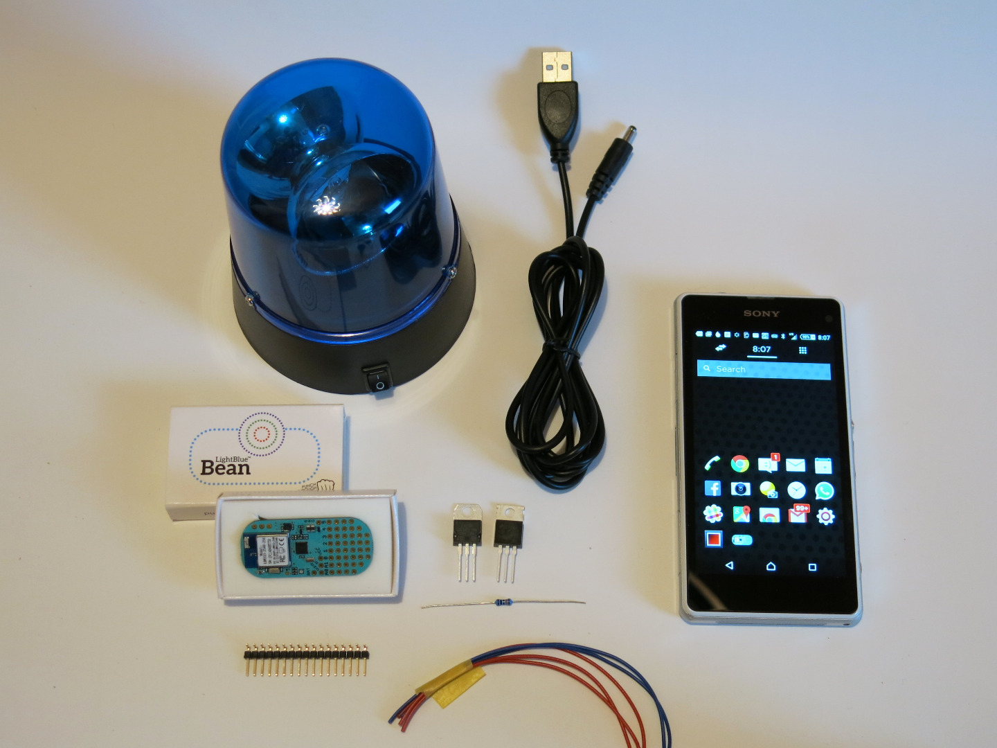
If you want to build one...
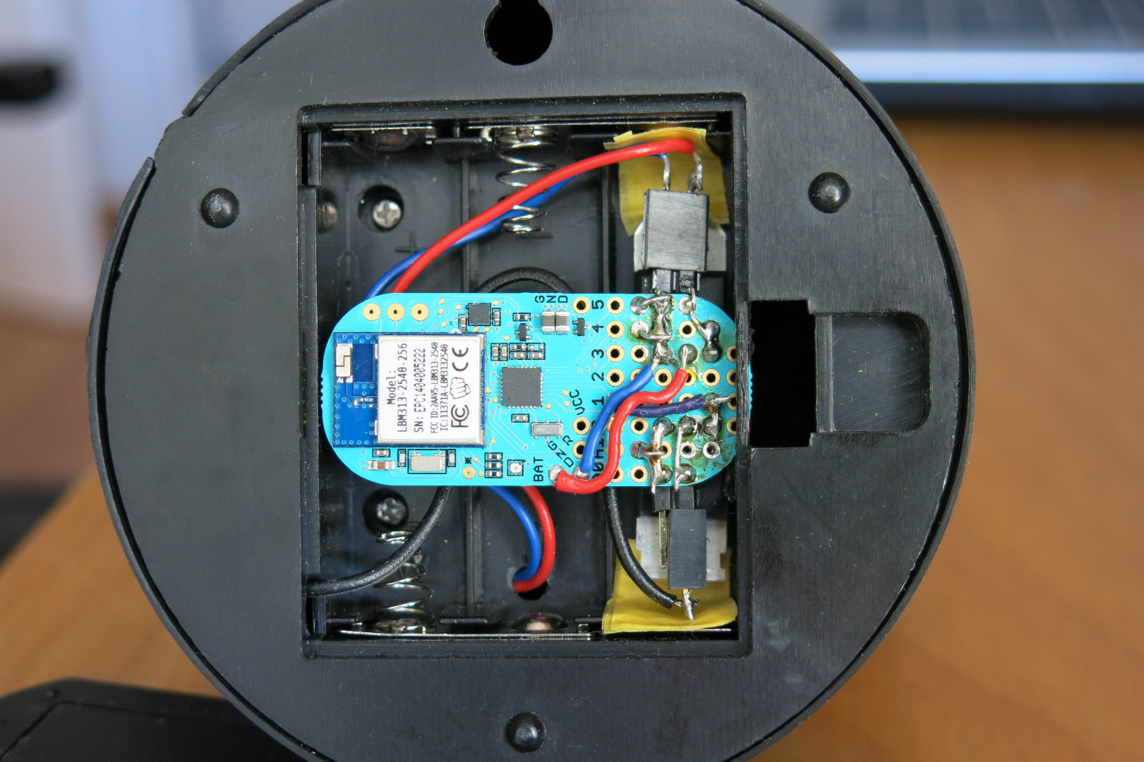
You will need at least basic soldering skills. And some reverse-engineering mindset, in order to modify the beacon.
As it touches several disciplines, this may be a journey taking a certain amount of your time.
iPhone/iPad and Android users are both supported.
Have no programming skills? no problem. The pre-built files and packages are available here below.
Do it at your very own risks! Triple-check all steps. Please let me know of any errors. Have fun!
Needed stuff
Mini USB police beacon.
> $4. Available at Conrad, Maplin, etc.
Lookup on Google for "mini police beacon usb".
LightBlue Bean.
Ca. $30. Available on MakerShed.com, Amazon, etc.
Components, available at your usual electronics store:
- FQP30N06L < $1.5
- LD1117V33 < 0.30 cts
- 100kΩ resistor < 0.15 cts
- Some wire
And, of course, a Bluetooth Low Energy enabled smartphone (Android or iOS).
Tools
- Soldering tools and supplies
- Mini screwdrivers
- Multimeter
Electronics
Power supply
From the Beacon's 5V USB voltage, the LD1117V33 generates a 3.3V voltage supply, to power the Bean. Do not power the Bean with 5V !
The S1 on-off switch, originating from the Beacon, switches everything on/off.
Switching the load
Using a FQP30N06L MOSFET, we will power the Beacon's motor and lamp, by opening/closing its ground connection. This transistor can switch 10A for Vgs = 3.3V, which is largely enough.
The Bean's D1 pin, as output, drives the MOSFET's gate, with a 100kΩ pull-down resistor, so as to block when D1 is left as input.
D1 will be set as output by our sketch (see below), and driven high/low in order to command the Beacon.
Soldering
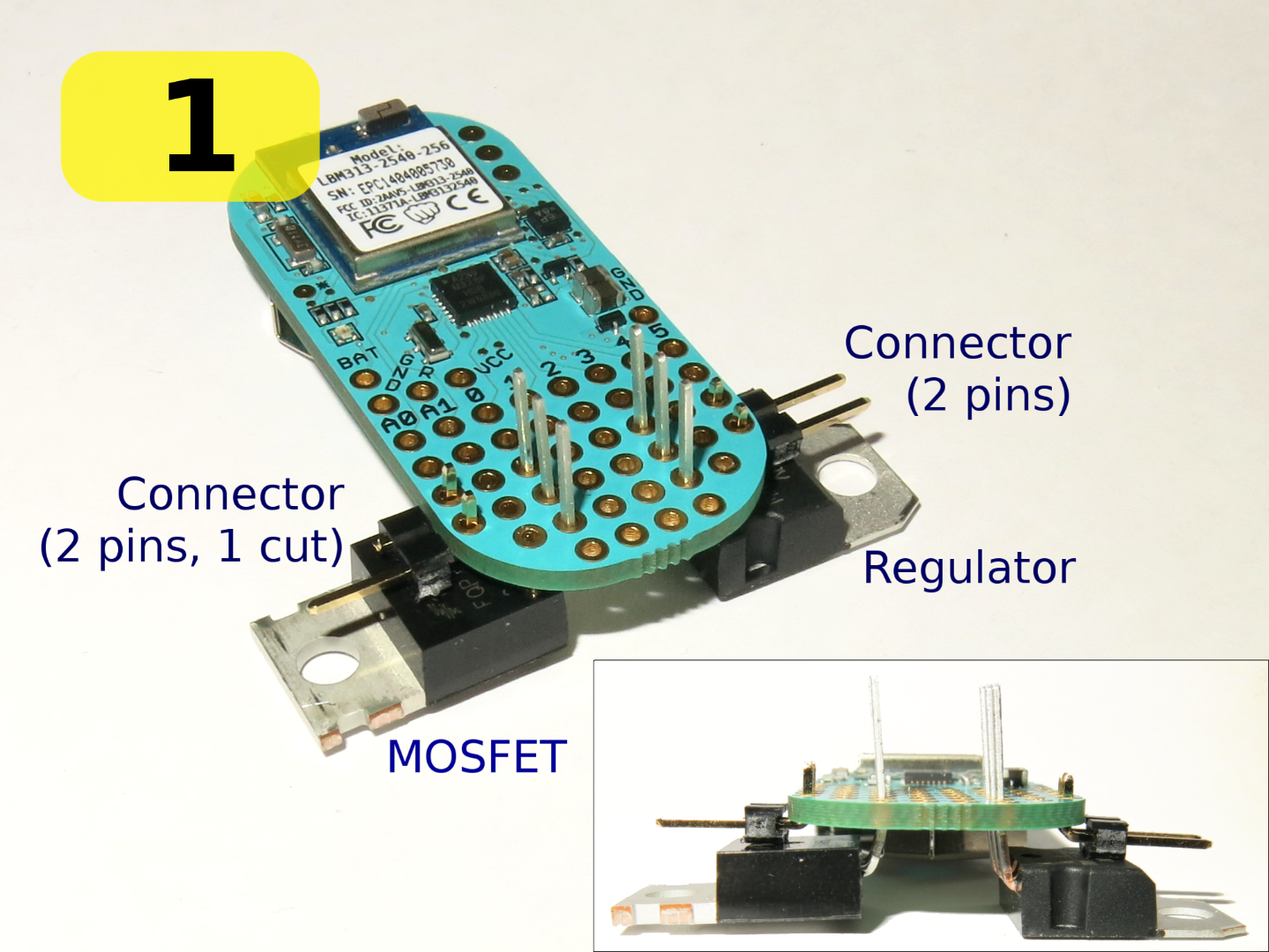
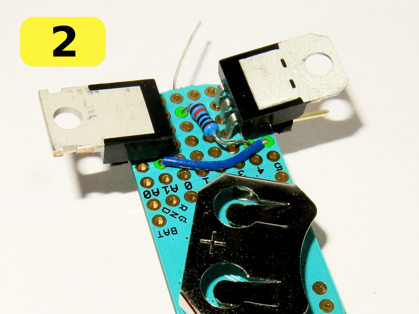
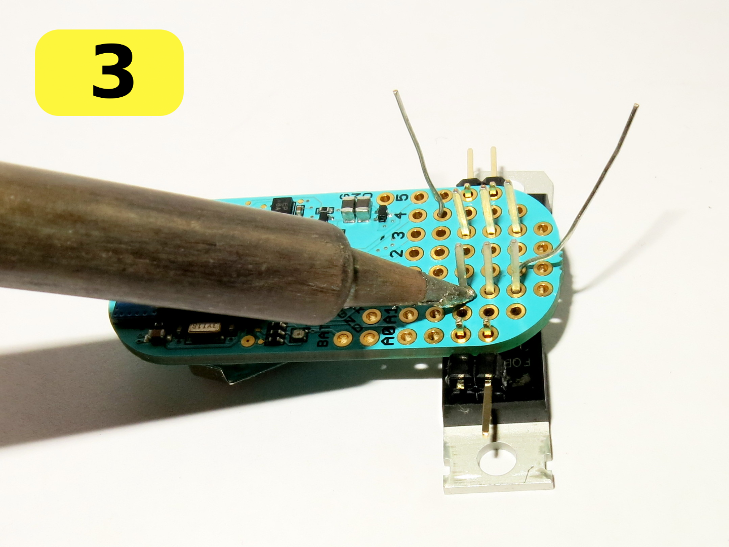
In this steps we will mount all the electronic components according to the design shown in the previous step. You may place them differently, and the present step just shows how I did it.
(1) Place the components
- Turn the Bean battery side up.
- Bend the legs of the regulator and MOSFET 90° towards their top side.
- Take two pieces of 2-pins-long male connector. One of both has its outside pin cut as indicated.
- Place connectors, MOSFET and regulator on Bean's protoboard, as shown.
(2) Resistor
- Place the 100 kΩ resistor and blue wire as indicated. The connected pads are highlighted in green.
(3) Solder legs
- Flip the whole.
- Solder all the legs, then cut their excess.
(4) Solder connections
- Add and solder the blue, red and yellow wires as shown.
- Make solder bridges between pads, as indicated by grey connections.
Arduino Sketch
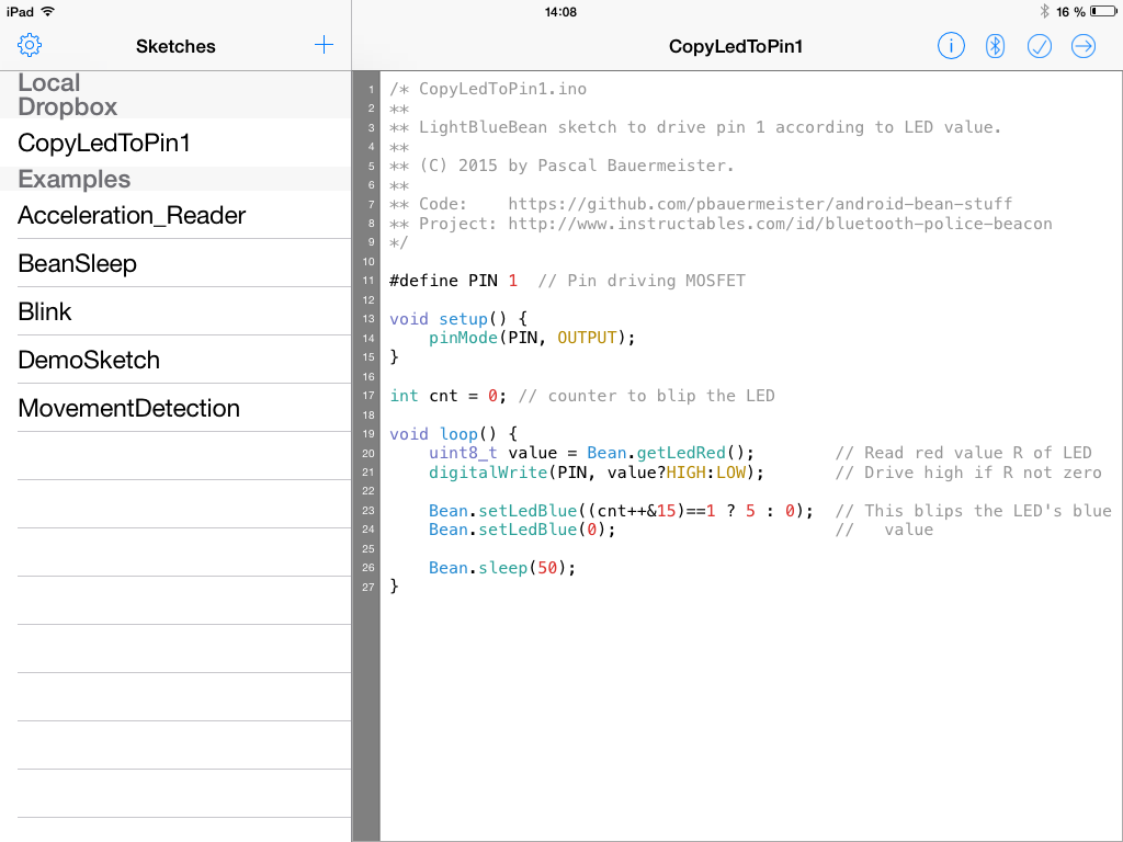
This step should be completed before integrating the Bean into the beacon.
How the sketch works
We want the Bean to drive the MOSFET according to the state of the RGB LED. The sketch (shown above) does the trick, and in the same time, emits blue blips, to tell it is running.
Let's install the sketch
1) Get the sketch file
Download the sketch's (CopyLedToPin1.ino file) latest version from the project on Github.
If you have installed a sketch on a Bean before, you can skip the rest of this step.
2) Program it into the Bean
There are multiple ways to load a sketch into a Bean.
My preferred ones rely on the mobile device, which is supposed to have BLE anyway, in order to operate the Bean later.
Another method (that I did not try) uses the Arduino IDE on a computer, and needs the computer to have BLE available.
Variant 2a) Use your Android BLE phone
i. Get the sketch into your phone: Copy the sketch file (obtained in 1. above) to your phone's sdcard (visible on your computer via USB).
ii. Install the Bean Loader app into your phone: start Google Play, and search for beanloader (without space).
iii. Launch the Bean Loader app, locate the sketch as a file on your sdcard (under /storage/sdcard0 or 1 for resp. internal and external sdcard), and send it to the Bean:
- click the top-right Bluetooth icon and select wanted bean,
- Upload to Bean.
Variant 2b) Use your iPhone / iPad
On iOS, you can use Dropbox to transfer the sketch:
i. Copy the sketch file (obtained in A. above) on your computer's Dropbox folder as:
Apps/Bean Loader/CopyLedToPin1/CopyLedToPin1.ino
(please have these 3 levels of sub-folders Apps/Bean Loader/CopyLedToPin1 created into the Dropbox folder.)
ii. Install the Bean Loader app: start App Store, and search for bean loader (with a space between).
iii. Using the Bean Loader iOS app, connect to your Dropbox account, then locate the sketch under the Dropbox section, and send it into the Bean:
- click the top-right Bluetooth icon and select wanted Bean,
- Upload to Bean: -> arrow top-right icon.
Variant 2c) Use your computer
See http://legacy.punchthrough.com/bean/getting-start...
3) Power off and on the Bean
Power off and on the Bean after programming success, or between retries. In case of permanent problems, see the page http://legacy.punchthrough.com/bean/support/troub... (in particular §Reset your Bean).
Android Software
This step is for Android users only. iOS users can operate the Bean using the LightBlue app.
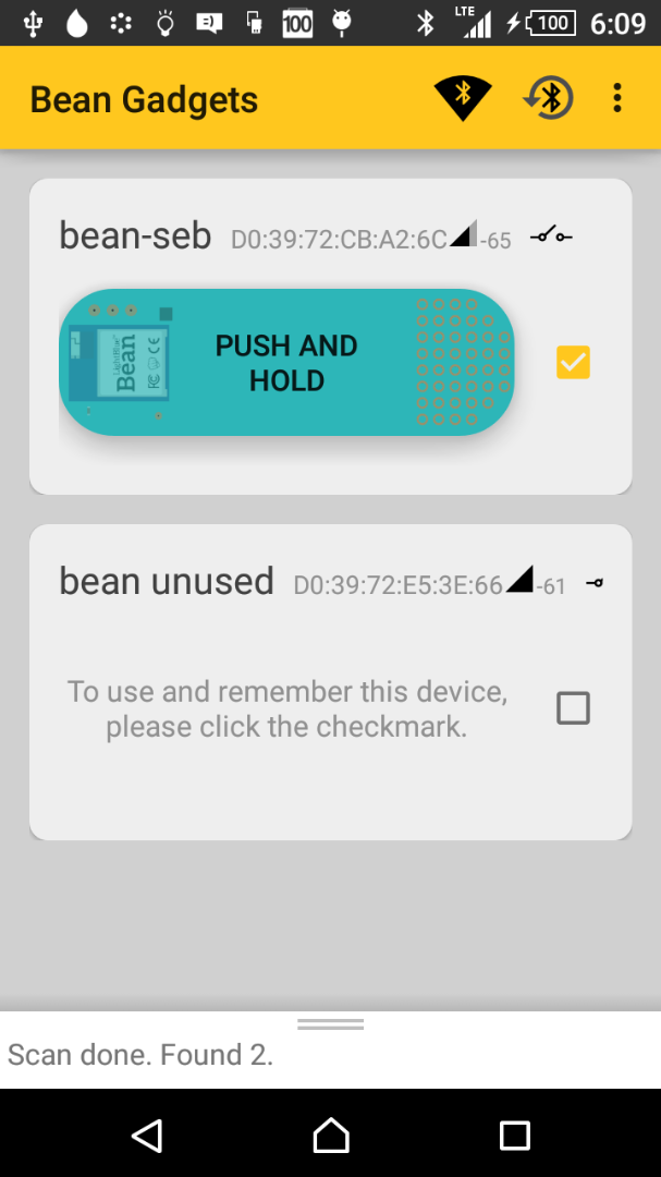
Because there is no LightBlue app version for Android, and also in order to try out the Bean SDK, I decided to write a small Android app, named Bean Gadgets, aimed at just controlling the LED.
This app deserves some improvements (e.g. accessing the Beans SDK from a service, and not from the activity), but it can be use already. Its design description is a bit beyond the objective of this Instructable, and may be the subject of a later one.
Installing
As the Android app is not yet released on the Play Store, you will need to install it manually:
1) Download the APK file there:https://github.com/pbauermeister/android-bean-stuff/releases/...
2) Connect your phone to your computer via USB, and copy it on the sdcard.
3) From a file manager app (e.g. ES File Explorer) on your phone, browse the sdcard, locate the APK file, and run it. It will install it.
Alternatively, if you have the Android development environment installed, do: adb install path/to/installation-file.apk
Yet alternatively, clone the Github project and build it.
Running
When the app starts, it scans to find Beans around, and displays what it finds.See the next step for more information.
Testing Out and Operating
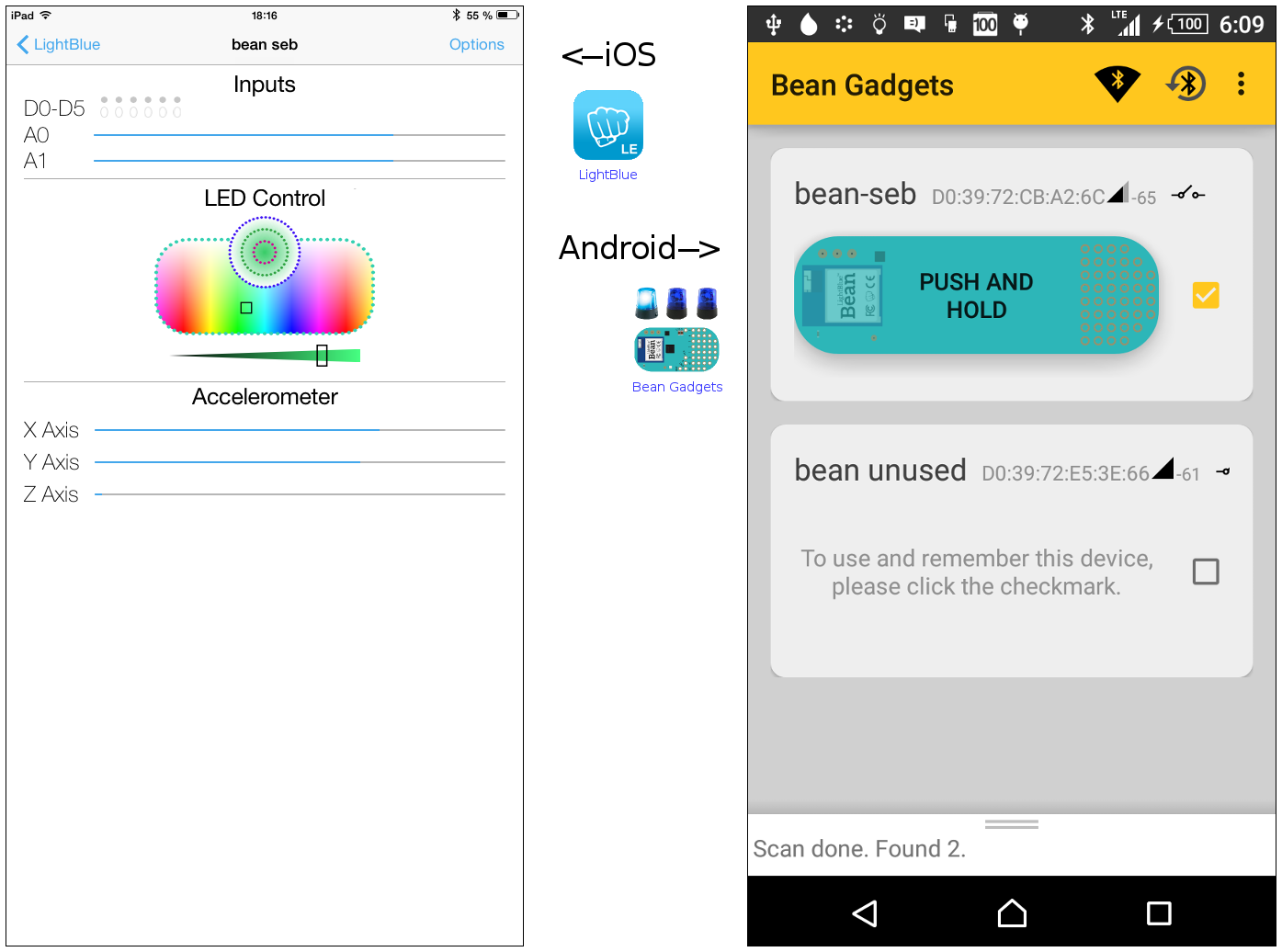
At any point, you can check that your Bean is up and running, after powering it with a coin cell, or with the voltage regulator, by switching its RGB LED on, using the Light Blue iOS app, or the Bean Gadgets Android one.
You can see that it is working as expected by checking for short blue blips of its LED, every approx. 2 seconds.
If you have multiple Beans and want to be able to distinguish them, you can rename them. Use the Bean Loader app (Android and iOS versions) to rename a Bean.
Controlling the Bean from Android
- Run the Bean Gadgets Android app. Turn on the Bean.
- It will scan for Beans. You can repeat scanning thanks to the first one of the top-right icons (the radar icon, on orange background).
- A card should appear on the screen, for each detected Bean.
- You may need to reset the BLE stack. Cluck the second icon (BT logo inside a circular arrow). Wait until the BT logo appears in the top of the screen (with black background) before scanning again.
Controlling the Bean from iOS
- Run the Light Blue app.
- Connect to the wanted Bean.
- Sliding the colour intensity to the very left would switch off the beacon. Any other intensity would turn it on.
Integrating Bean and Beacon
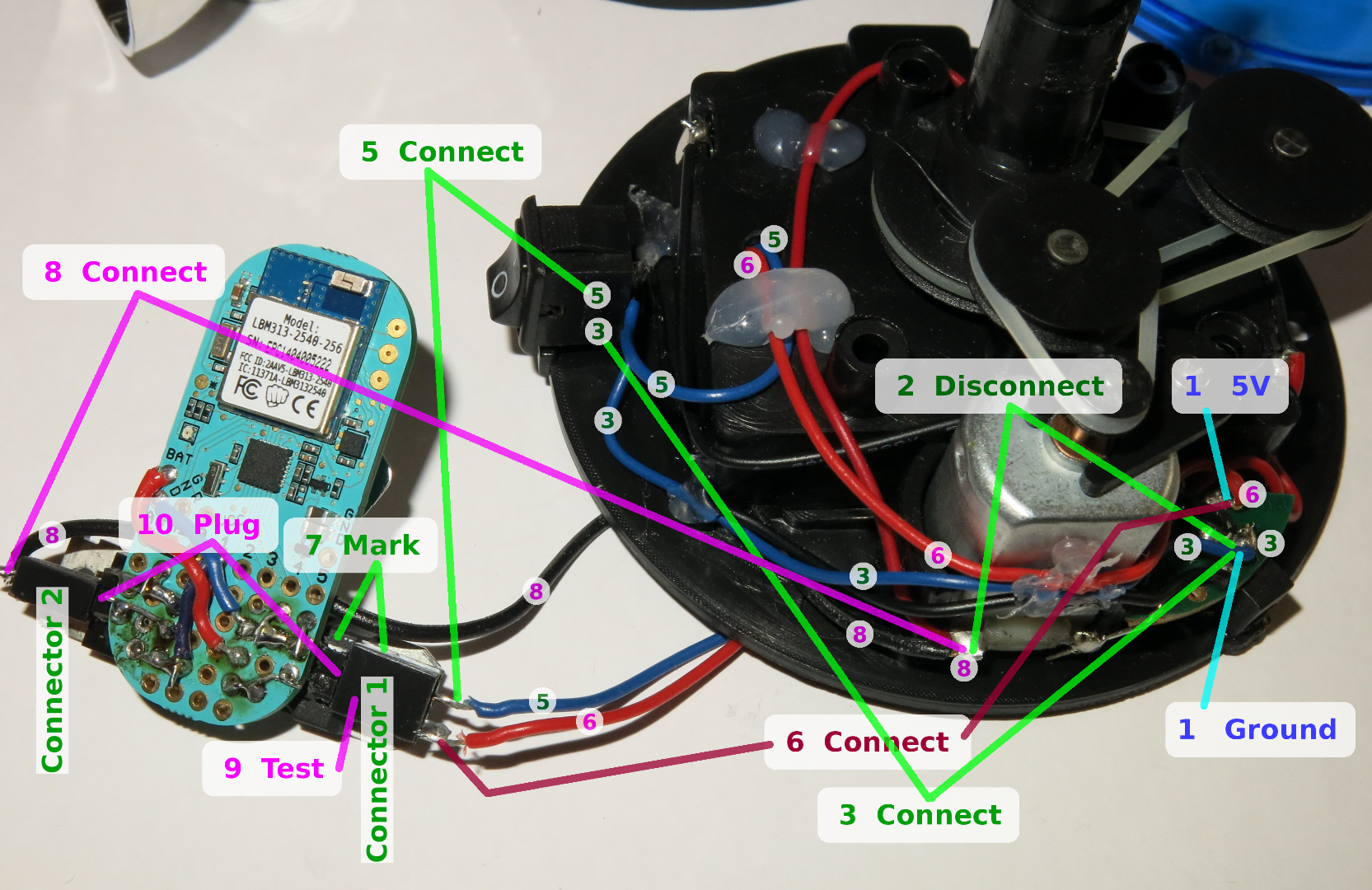
Now that the Bean has its sketch programmed, and that you can control it from your BLE phone, it is high time to integrate the Bean into the beacon.
0. Power off
Disconnect the beacon from its power adaptor, remove batteries, and turn the on-off switch to *on*.
[1] Locate the ground and the 5V
The ground is connected to the battery holder's (-) pole. Find a good ground point suited for later soldering.
The 5V is connected to the battery holder's (+) pole. Find a good 5V point suited for later soldering.
[2] Disconnect motor+lamp from ground
Locate the wire between the motor and the ground.
In the middle of this wire, there should be the on-off switch.
De-solder this connection and keep the switch for later.
[3] Connect ground to on-off switch
Connect the ground located in (1) to one contact of the on-off switch.
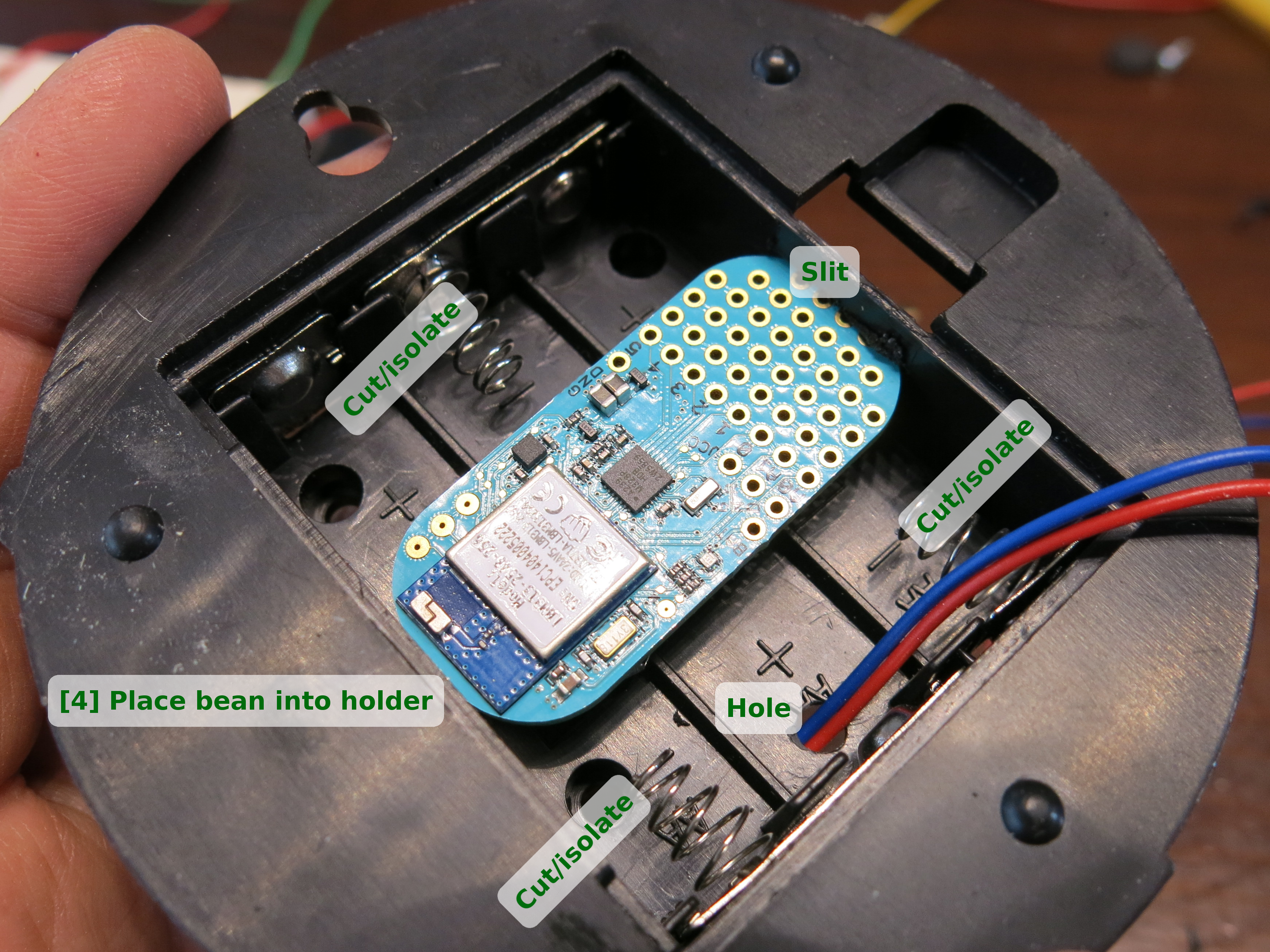
[4] Place Bean into battery holder
If needed, make a slit into the battery holder.
Find out or make holes for the wires.
Evaluate the needed length of the wires (with a few centimetres of margin).
Isolate the battery holder's contacts.
Remove Bean from holder.
[5] Connect ground from on-off switch to female connector 1
Connect the other contact of the switch to the female connector 1.
[6] Connect 5V to female connector 1
Connect 5V to female connector 1.
[7] Mark connector 1
Mark side of connector 1 to avoid later polarity mistakes.
[8] Connect motor+lamp to female connector 2
Connect motor+lamp contact found in (2) to connector 2.
[9] Test power (without Bean)
Do not connect the Bean yet.
Plug the 5V jack into its socket, and check for voltage on connector 1: 5V when switch is on, 0V when switch is off.
Check that connector 2 is properly connected to motor (beep with multimeter).
Check that connector 2 remains at 0V whatever the position of the switch.
[10] Connect Bean and test MOSFET
Plug connector 1 into its male counterpart on the Bean. Mind the polarity. Turn on the switch. Bean's LED should go on for a short while.
Turn the Bean on/off via the Android Bean Gadgets or iOS LightBlue apps, as described before. With an ohm-meter, check if circuit is open between the ground and connector 2 (MOSFET drain):
- When Bean LED is off: circuit is open.
- When Bean LED is on: circuit is closed.
Plug connector 2 into its male counterpart on the Bean. Operate the Android or iOS app; the beacon motor and lamp should be duly controlled.
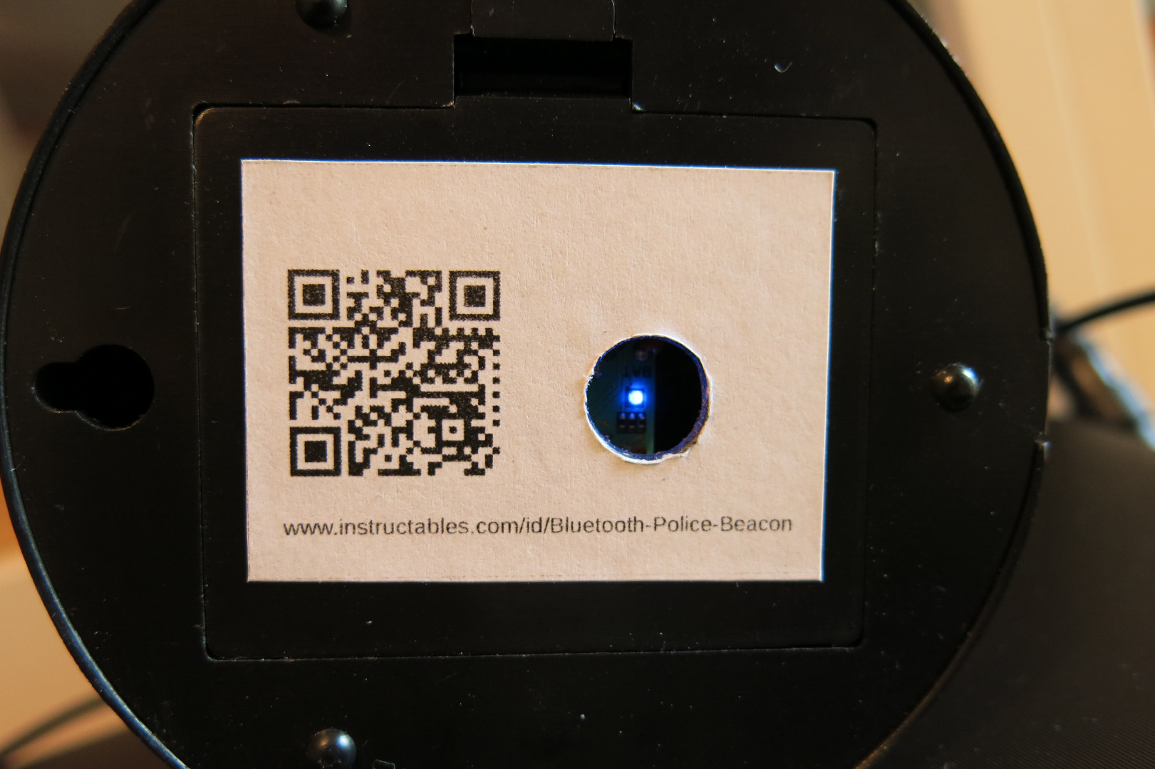
11. Make hole into battery lid
Make a hole in the lid, placed so that you can see the Bean's LED, which is important for checks.
Place Bean into battery holder, close lid.
Done!
Conclusion
The Lightblue Bean is a very cool platform.
You can use the ideas presented in this Instructable to remotely control any other kind of small loads, from your phone via Bluetooth Low Energy.
For more advanced functionalities (more complex commands, data readout, etc.), the RGB LED trick will not work, and, with the same hardware setup, usage of serial communication between the phone and the sketch will be necessary. But this goes beyond the objective of this project.
I had a lot of fun creating this project, and learned a couple of things. I wish the same to you.
Thanks for reading!