Bluetooth Control Home Automation
by Tech Hunt in Circuits > Arduino
15283 Views, 33 Favorites, 0 Comments
Bluetooth Control Home Automation
Hello,
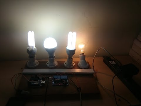
This project is all about building the most simplified home automation device using an arduino and a bluetooth module. This one is very easy to build and it can be built in a few hours. In my version which i'm explaining right here, i can control up to 4 home appliances using my Android smartphone. Let's have a look at the list of materials and tools you'll need.
COMPONENTS REQUIRED
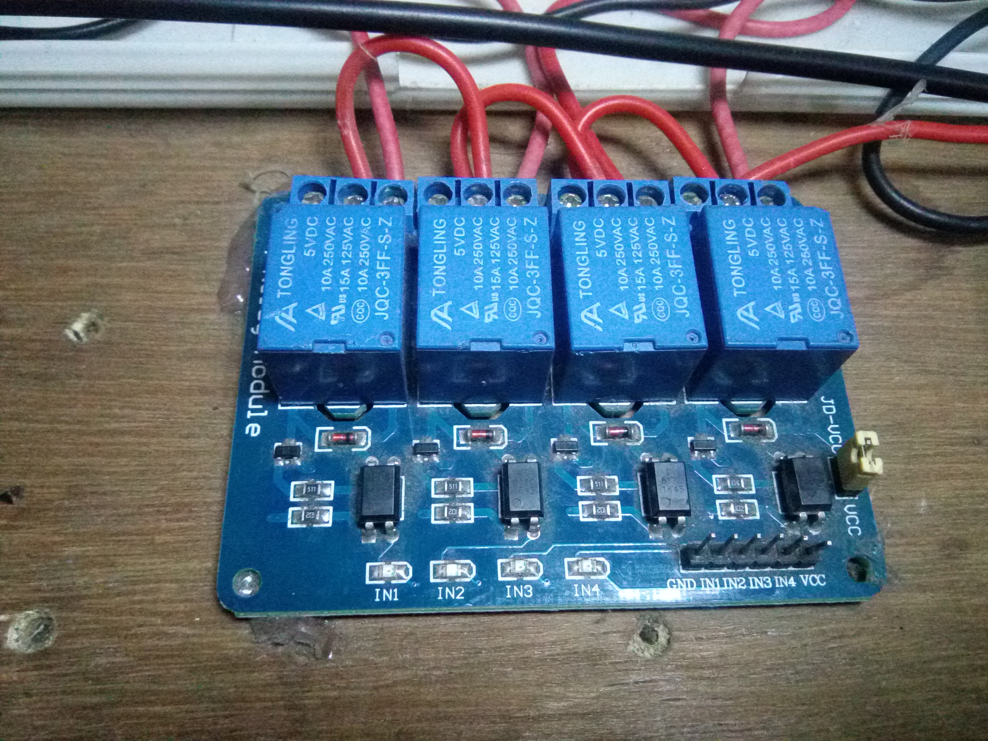
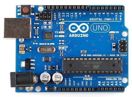
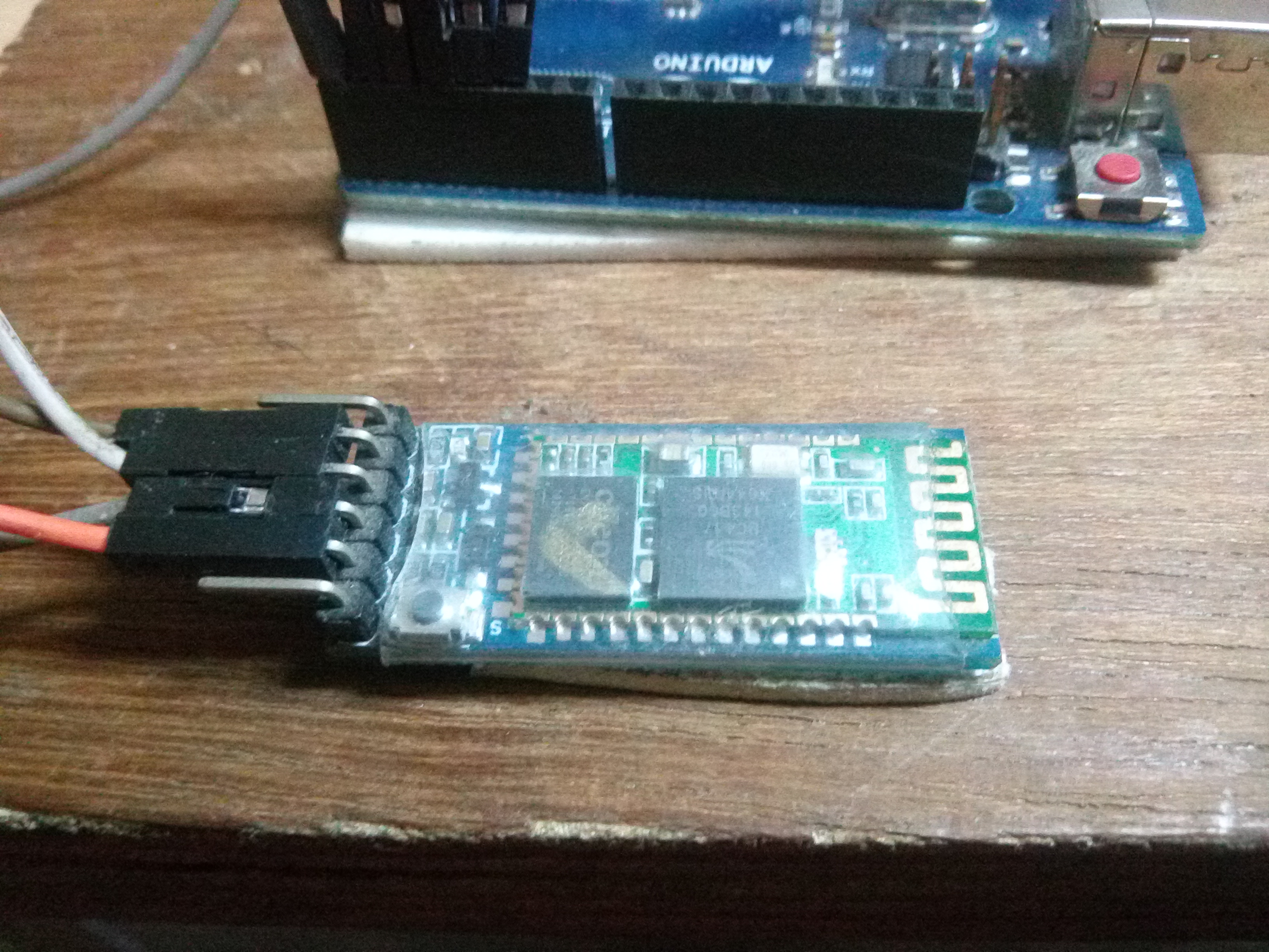
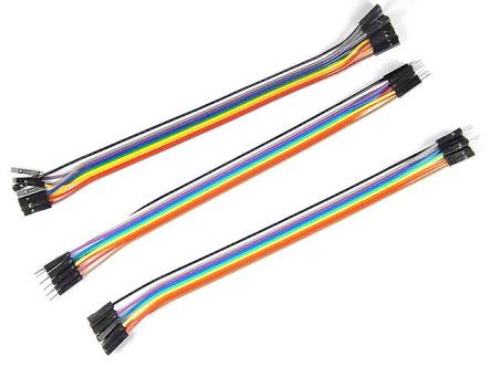
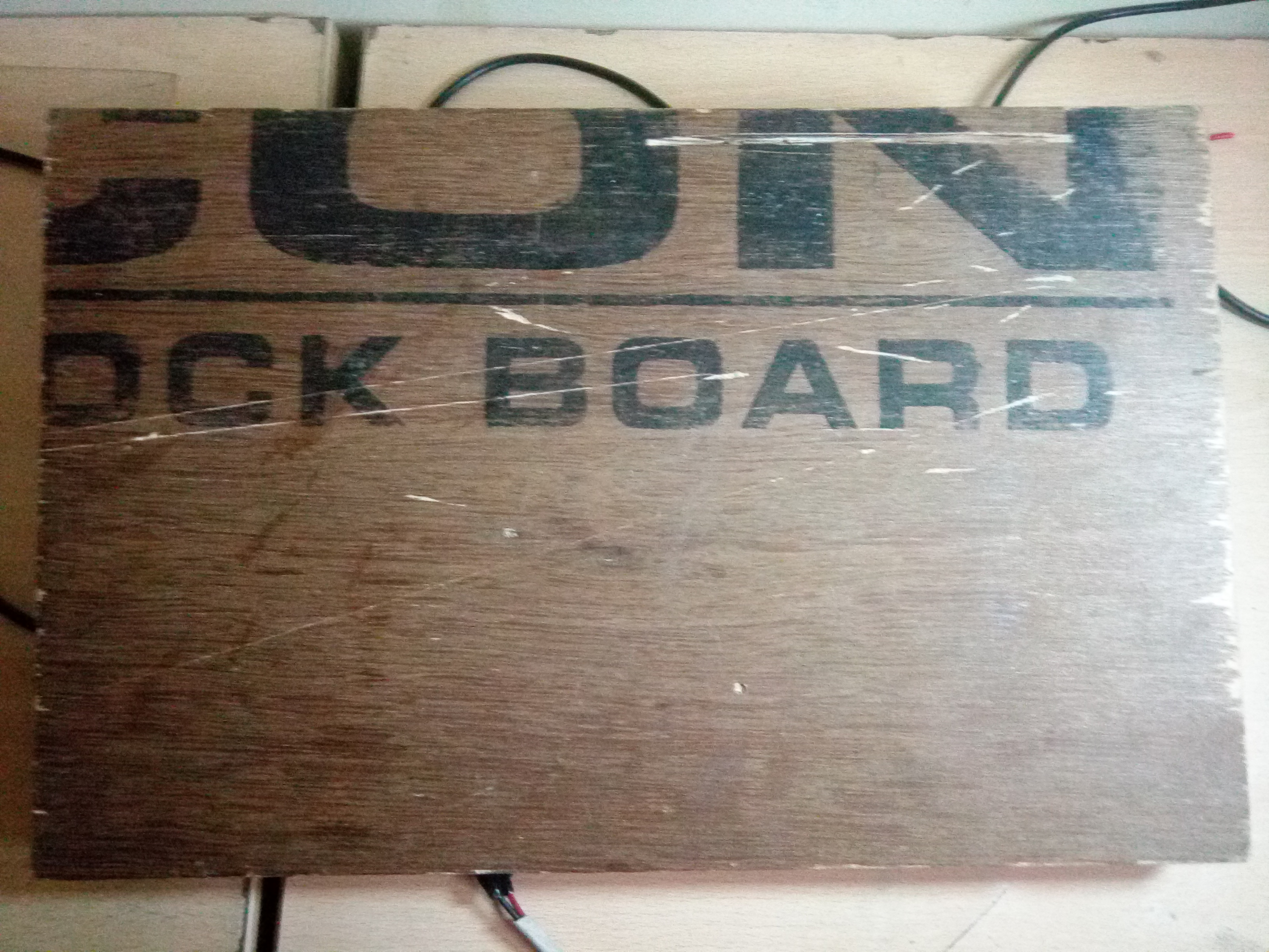
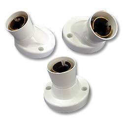
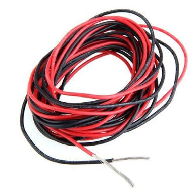
Guys, here is a list of materials you would require for making this simple project.
- Arduino uno
- 4-chhanel relay module
- Bluetooth module (Hc-05)
- Jumper wire
- wooden bord
- Bulbs Holder
- wire
- 5v Power supply
List of Tools.
- Soldering kit
- Glue gun
- Android Smartphone
- Screwdrivers
- Wire strippers etc:
That's all we need...
Circuit Diagram and Connection
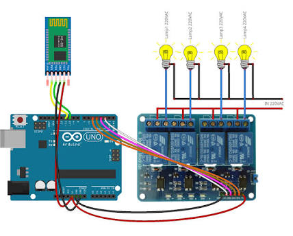
Connect circute belove stap
Step 1. arduino connect to bluetooth module hc-05.
Step 2. hc-05 vcc and gnd connect to arduino vcc 3.5v and gnd.
Step 3. hc-05 rx and tx connect to arduino sequencely tx and rx (0 and 1).
Step 4. 4-channel relay module have 6 pin vcc, gnd, 1-4 relay switch.
Step 5. relay module connect arduino vcc gnd and arduino pin 2-5.
NOTE:- In diagram Bluetooth connection is Wong Bluetooth module Rx and Tx connect with sequence arduino Tx and Rx (0 and 1) number pin
The Software


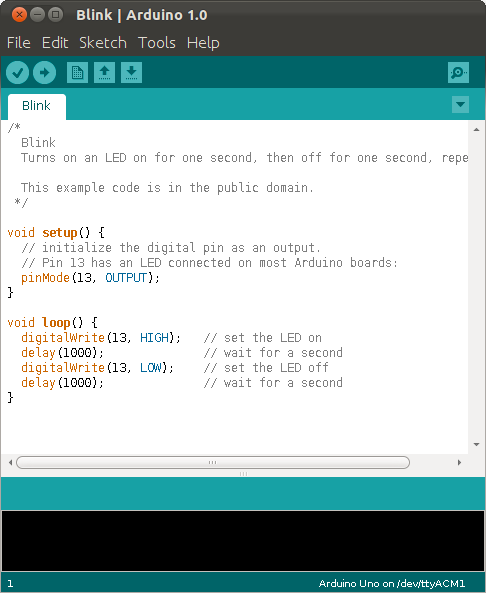
we are using arduino software in pograming inarduino uno
Download the Arduino IDE from here.
The Code
This code uses softwareserial.h to configure rx and tx pins in the Arduino. These rx and tx pins are connected to the tx and rx pins of the HC 05 Bluetooth module respectively.
The bluetooth module receives data from a paired android device and triggers the relays with respect to the data received. For example, in my code if the received data is the character "A", the relay 1 will be triggered ON and if the received data is the character "B", the relay 1 will be turned OFF. Similarly all the relays can be turned ON/OFF using bluetooth commands. Refer the code for detailed comments.
Downloads
The Android Application
.png)
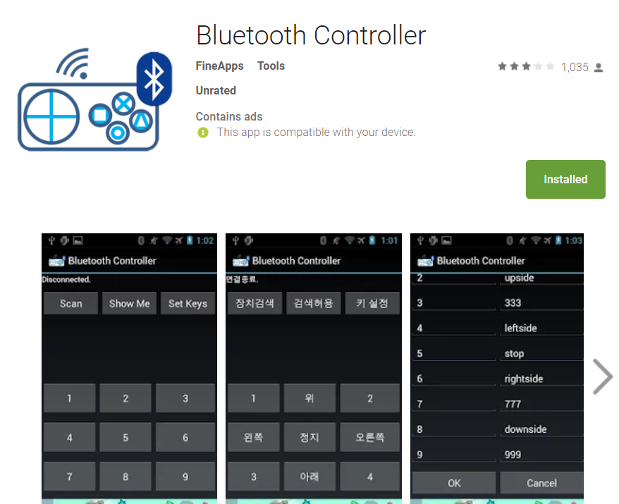
download android app here
As mentioned above, the micro-controller triggers each relay according to the data it receives through the Bluetooth Module from an Android device. So we need an Android application to send these data to the HC 05.
I made a customized application using the MIT App inventor. I've attached the 'blocks layout' of my application as a PDF here for reference for those who are going to make their own app using the App Inventor.
Instructions for the Android App
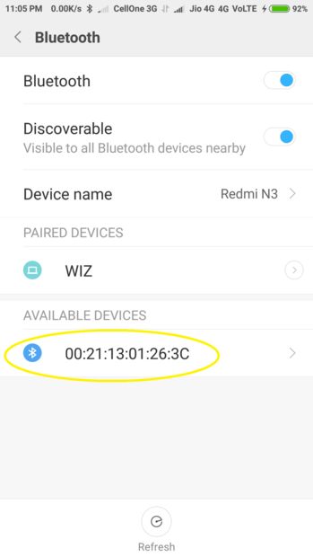
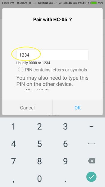
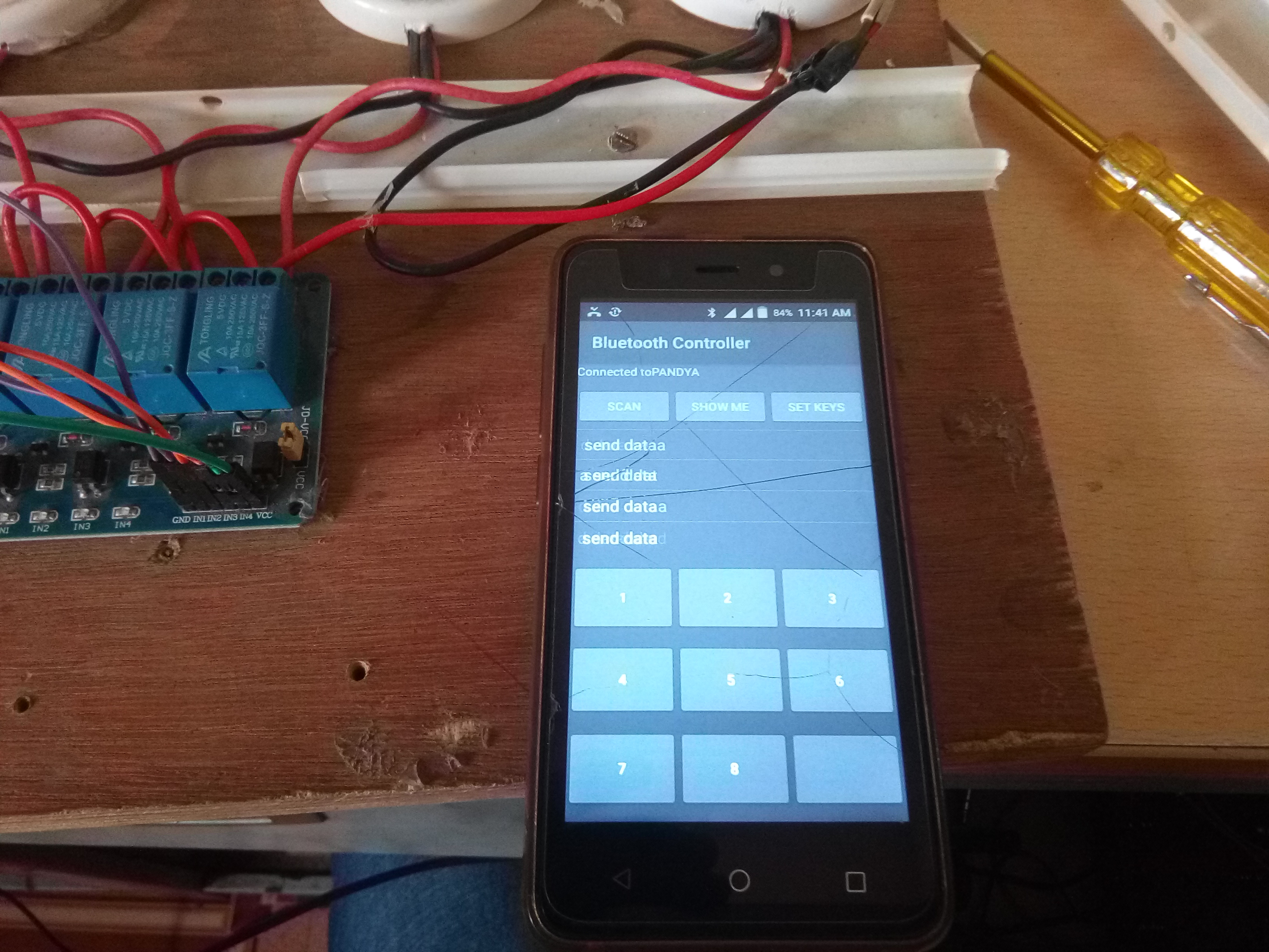
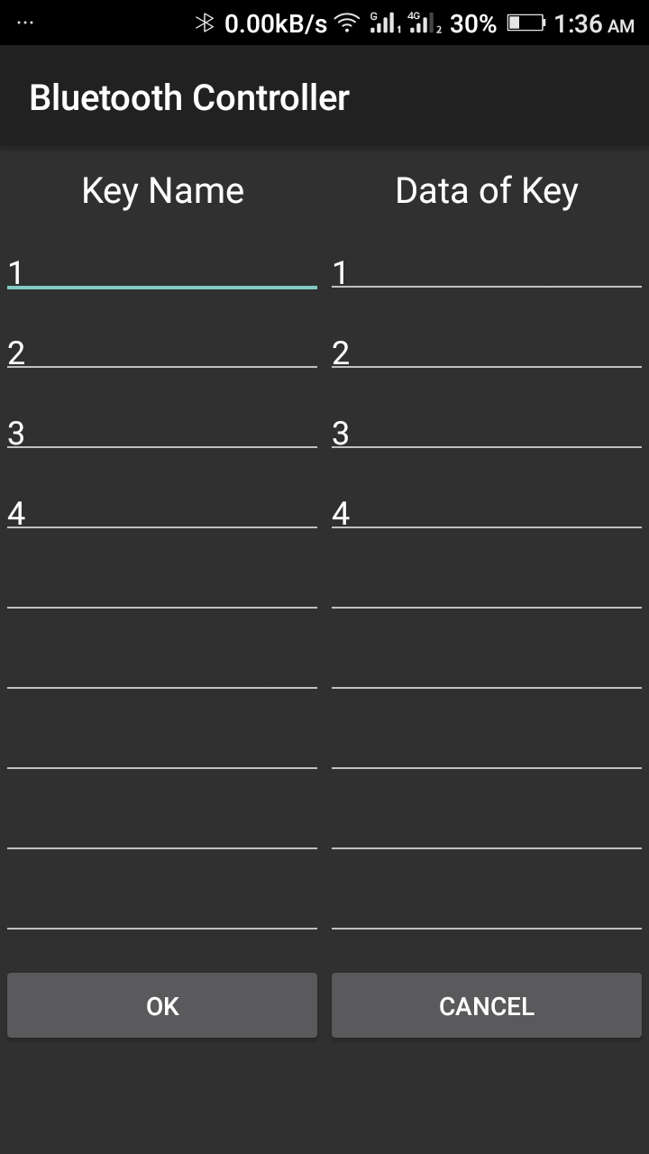
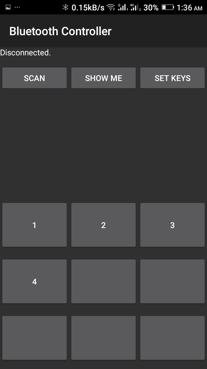
You have to pair the HC-05 Bluetooth module to your android device before you could use it in the app.
Step 1 : Open your device's bluetooth settings and search for new devices, make sure the led on HC05 module is blinking continuously (Pairing Mode).
Step 2 : Select HC 05 ( or you'll see an address ending with "C" as shown in the picture.)
Step 3 : Enter the PIN "1234" and press OK.
Step 4 : Open the "Bluetooth Controller" app and click the bluetooth button on the top of the screen.
Step 5 : Select "HC 05" from the list.
Step 6 : Use the respective switches to turn ON/OFF the relays 1,2,3,4.
Step 7 : Click the Master to turn all the relays ON/OFF in a single click.
Assembling the Components.
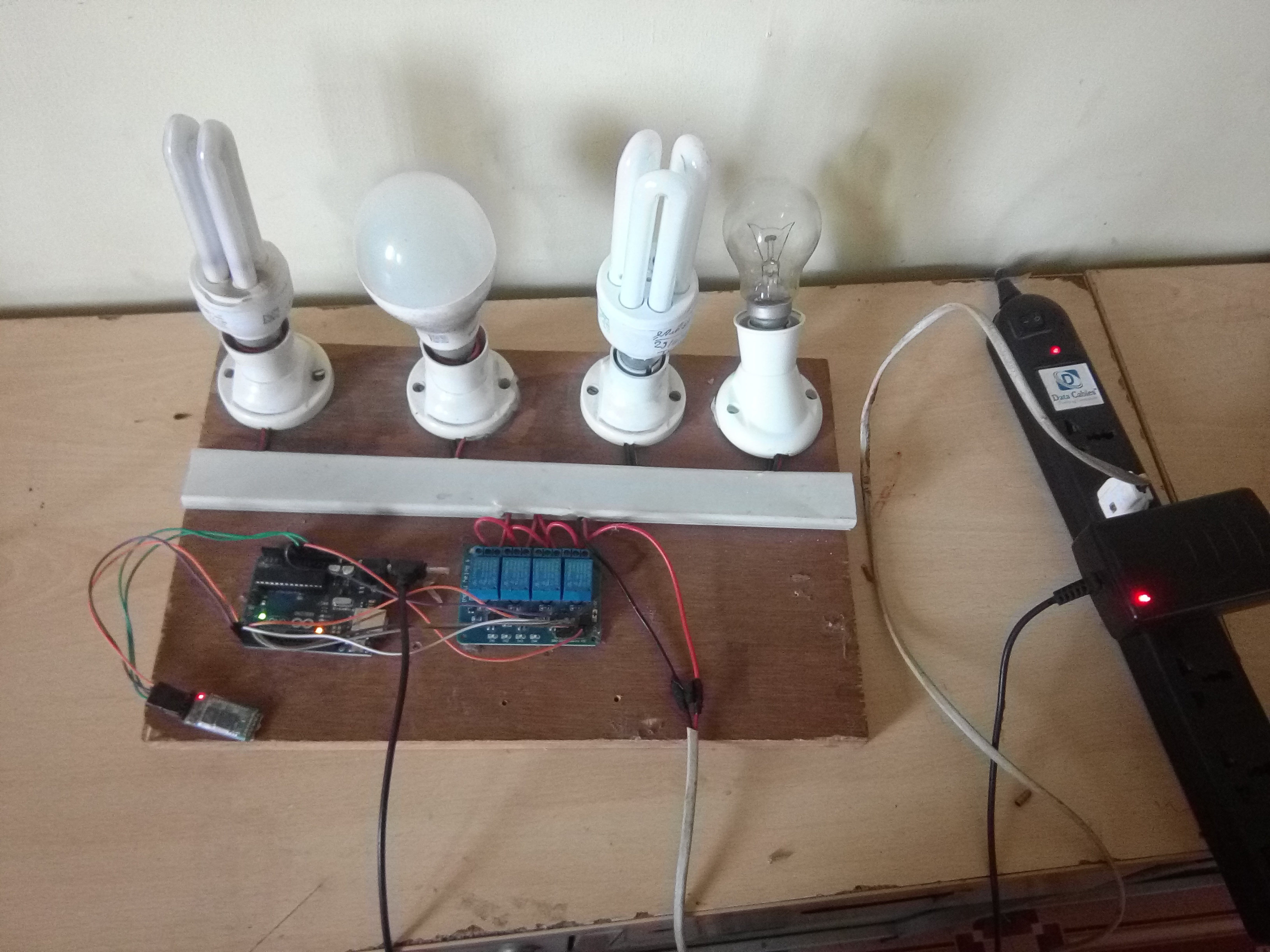
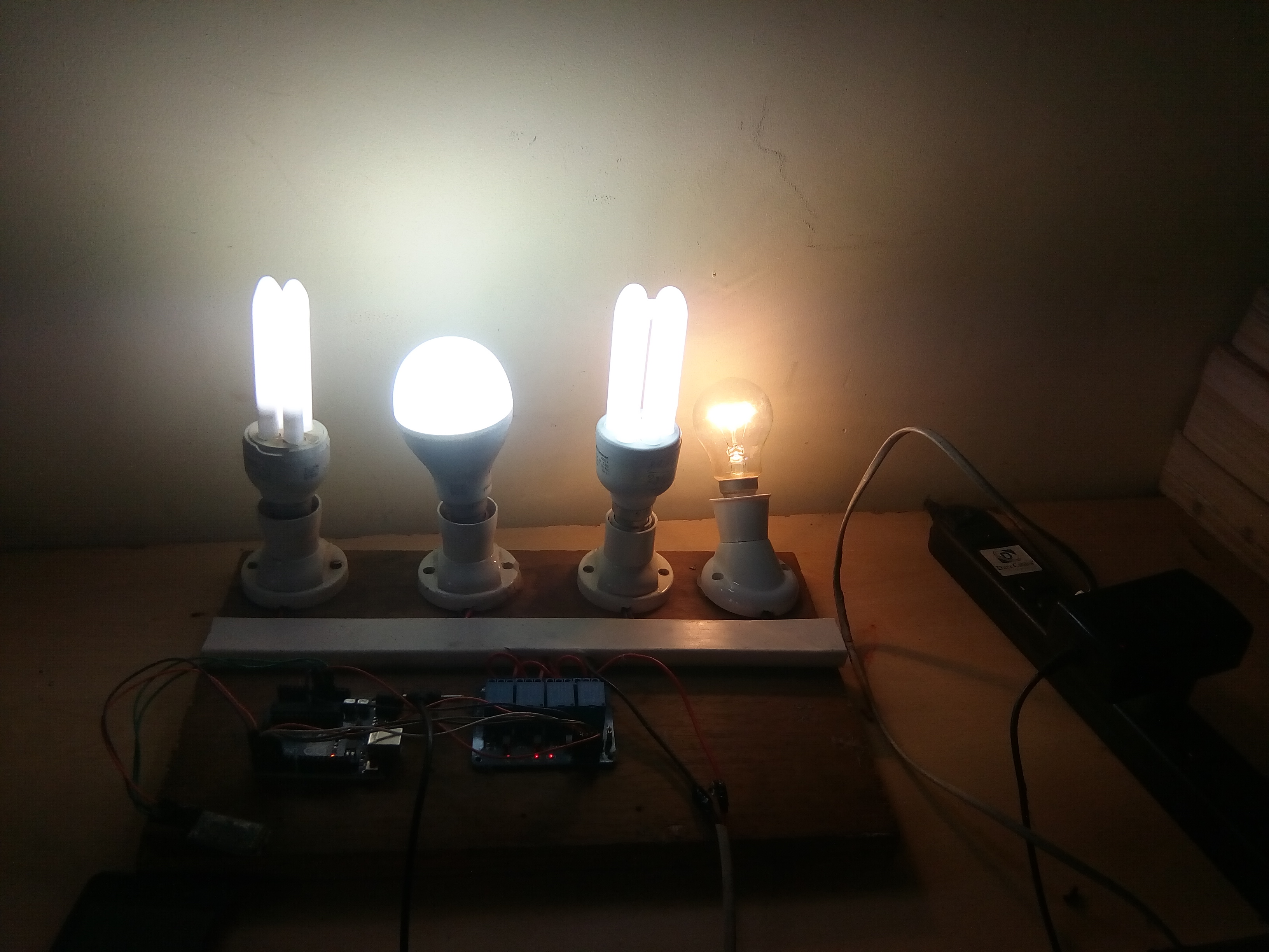
The assembling all component above picture