Bluetooth Air Horn
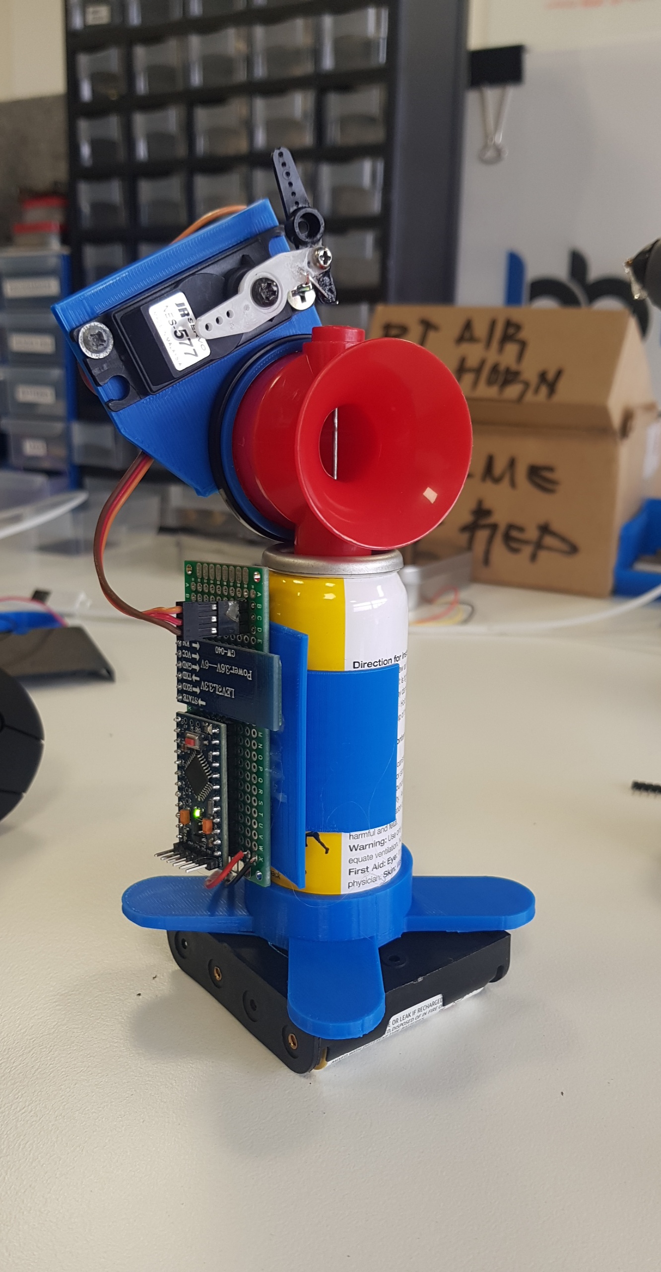
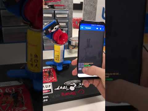
As a long time lurker I finally decided this project was worthy of a write up (also I'm killing for an instructables tshirt). I love this site and hope you enjoy this project.
IMPORTANT!
Just a quick heads up, there are optional steps in this build. Your horn will be fully functional by step 6 however I have included further options to monitor battery levels, change your Bluetooth device name and more!
Also if anything isnt clear please let me know! I'll amend this write up with anything I may have missed.
Tools & Materials
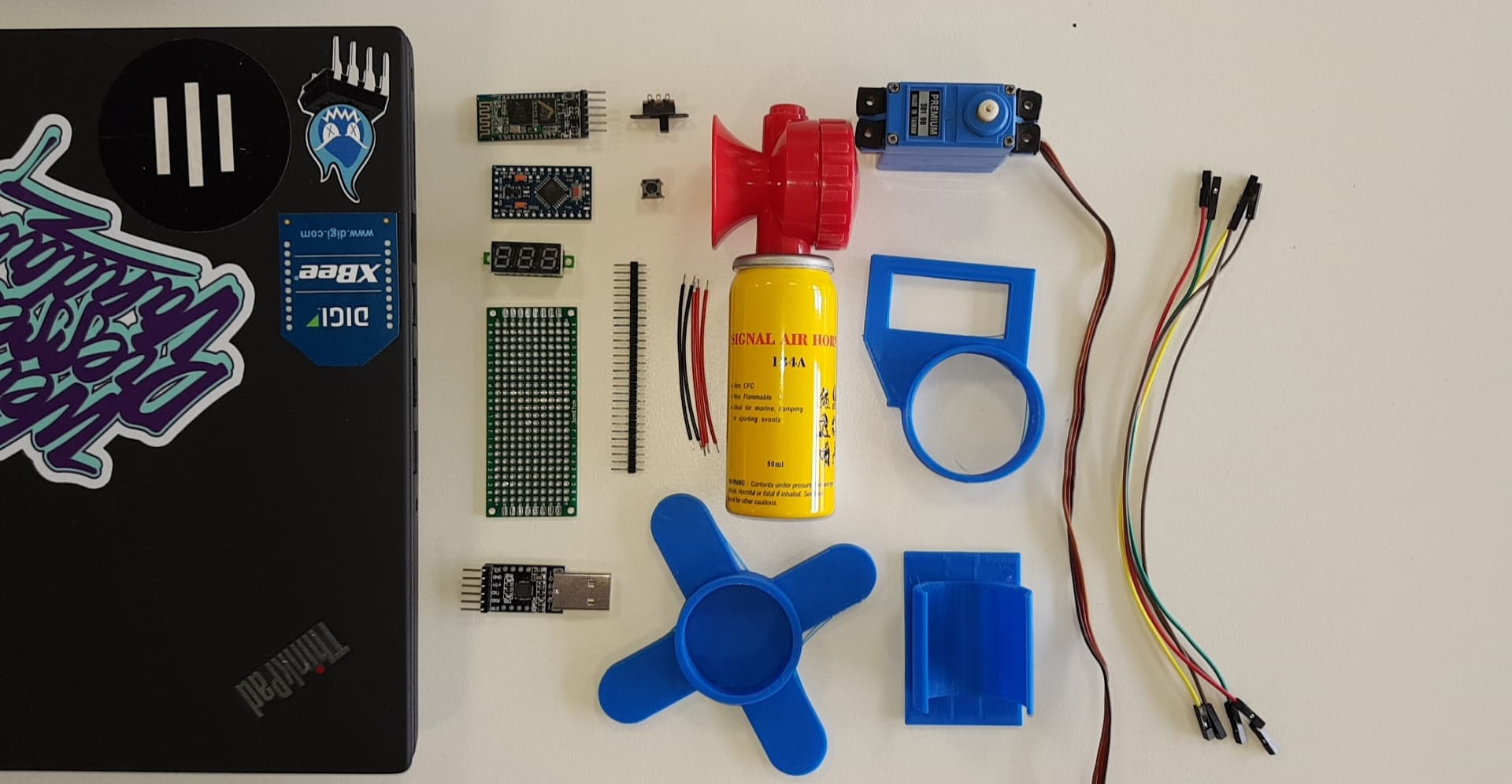
Will keep the links updated if any go offline.
Components Required:
- Arduino Pro Mini 3.3v 8mhz or 5v 16mhz (link)
- UART TTL Programmer (link)
- HC-05 Bluetooth Module (link)
- Header Pins [about ~25 should do] (link)
- Hookup Wire (enough to connect the pins on the breadboard)
- Air Horn 134A (link)
- 180 Degree Servo Motor (link)
- Solder-able breadboard [cut to size] (link)
-
4 x AA Battery Clip [Not Pictured] (link)
-
4 x AA Batteries (Not Pictured)
Optional Extras:
Tools Required:
- Soldering Iron + Solder
- Hot Glue Gun
- Flush Cutters
- 3D printer (or 3d printing service online)
Flashing the Arduino
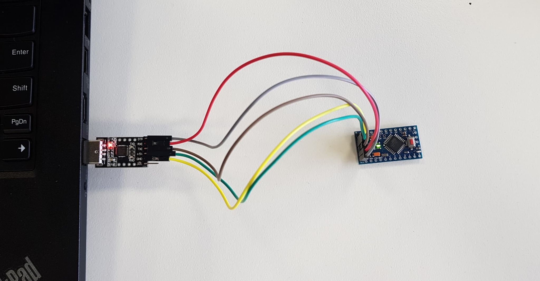
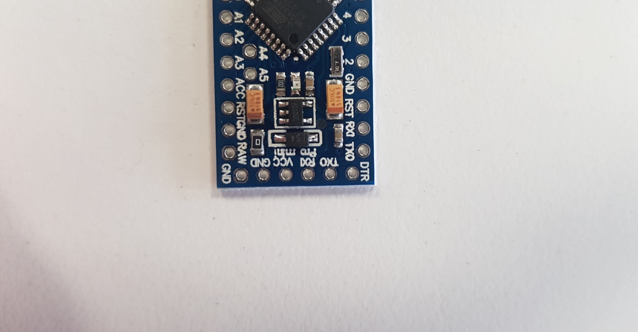
First of all you'll want to flash your Arduino. If it didn't come with the header pins soldered you'll need to solder the 6 pins labeled:
GND, GND, VCC, RXI, TXO, DTR (these will all be in a row on the bottom of your dev board)
Once you have soldered the pins you'll need to connect them to your FTDI Programmer as follows:
FTDI ----> Arduino
DTR ----> DTR
RXD ----> TXO
TXD ----> RXI
+5v ----> VCC
GND ----> GND
Now upload our test code (you can find the code here also):
#include <Servo.h><br>#include <SoftwareSerial.h><br><br><p>Servo hornServo;  // create servo object to control a servo<br>SoftwareSerial BT(10, 11);
char a; // stores incoming character from other device
int pos = 0;    // variable to store the servo position</p><p>void setup() {<br>
  BT.begin(9600);
  BT.println("Air Horn Active");
  hornServo.attach(9);  // attaches the servo on pin 9 to the servo object
  hornServo.write(10);  // sets the servo position</p><p>}</p><p>void loop() {<br>
if (BT.available())
  {
    a=(BT.read());</p><p>    if (a=='1')
    {
    hornServo.write(90);              // tell servo to go to position in variable 'pos'
    delay(15);
    BT.println("");
    delay(350);
    hornServo.write(10);              // tell servo to go to position in variable 'pos'
    delay(15);
    }

    if (a=='2')
    {
    hornServo.write(90);              // tell servo to go to position in variable 'pos'
    delay(15);
    BT.println("");
    delay(400);
    hornServo.write(10);              // tell servo to go to position in variable 'pos'
    delay(15);
    }

    if (a=='3')
    {
    hornServo.write(90);              // tell servo to go to position in variable 'pos'
    delay(15);
    BT.println("");
    delay(500);
    hornServo.write(10);              // tell servo to go to position in variable 'pos'
    delay(15);
    }</p><p>    if (a=='4')
    {
    hornServo.write(90);              // tell servo to go to position in variable 'pos'
    delay(15);
    BT.println("");
    delay(600);
    hornServo.write(10);              // tell servo to go to position in variable 'pos'
    delay(15);
    }

    if (a=='?')
    {
      BT.println("Send '1' for a sharp blast");
      BT.println("Send '2' for a longer blast");
      BT.println("Send '3' for a decent blast");
      BT.println("Send '4' for a deafening blast");
    }
  }
}</p>
Assembling the Board (Placement and Power Soldering)
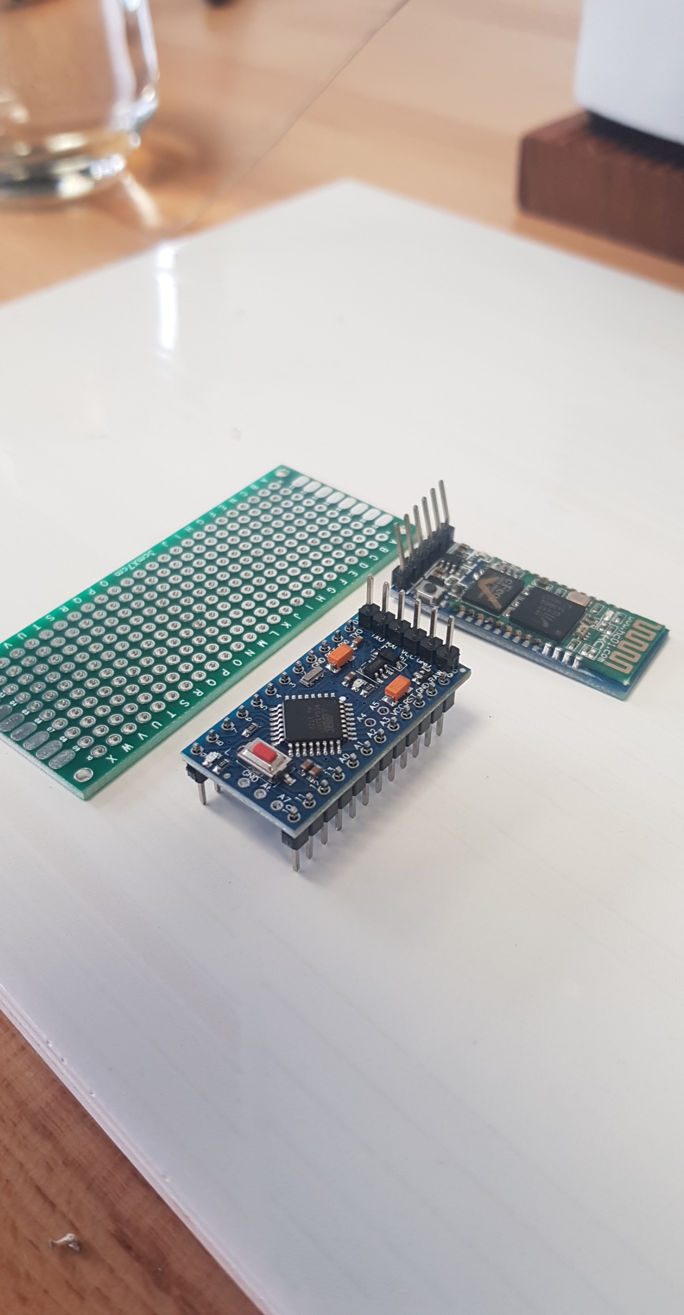
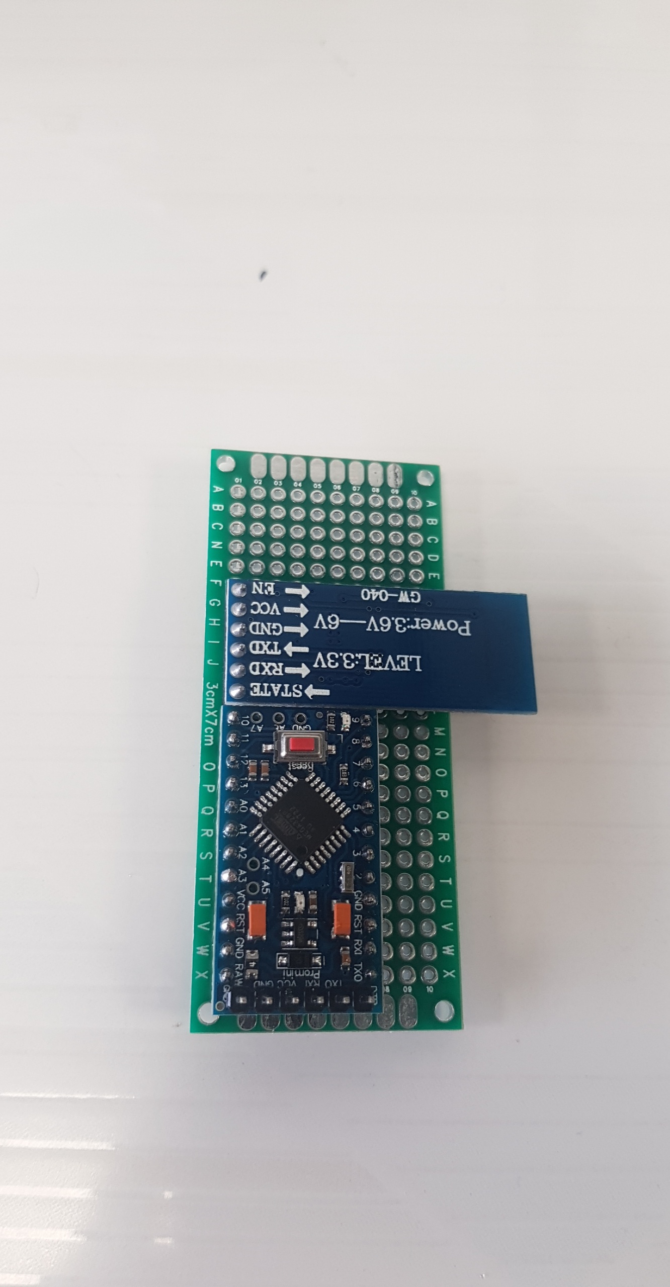
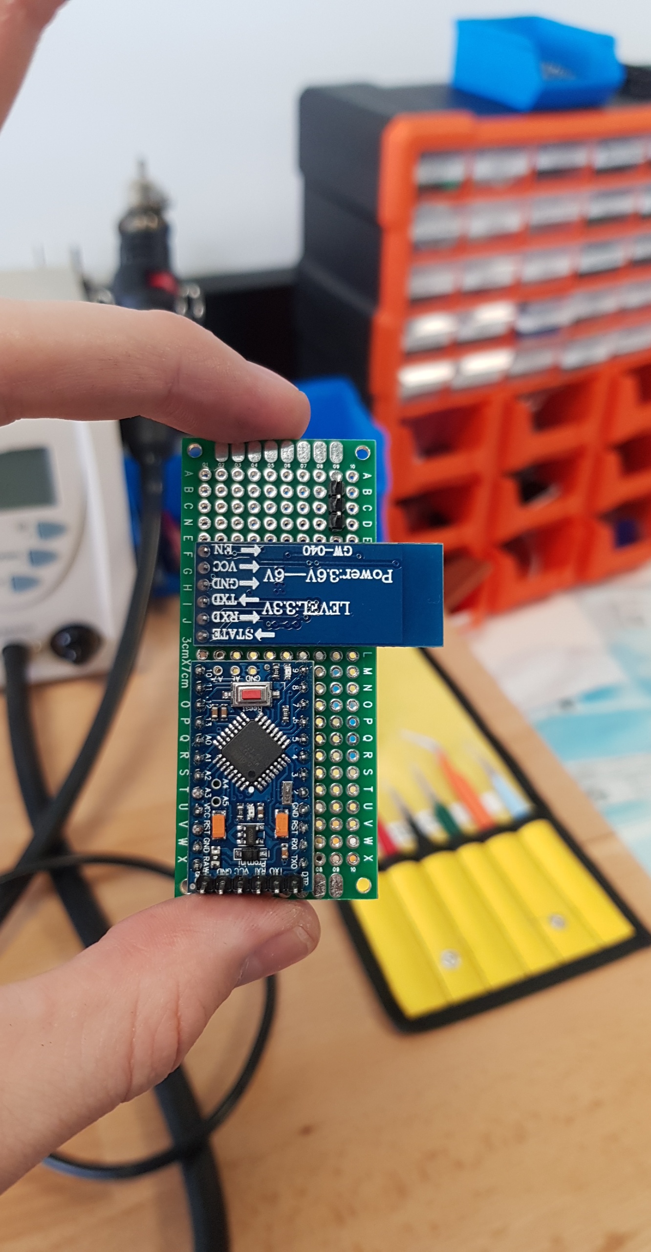
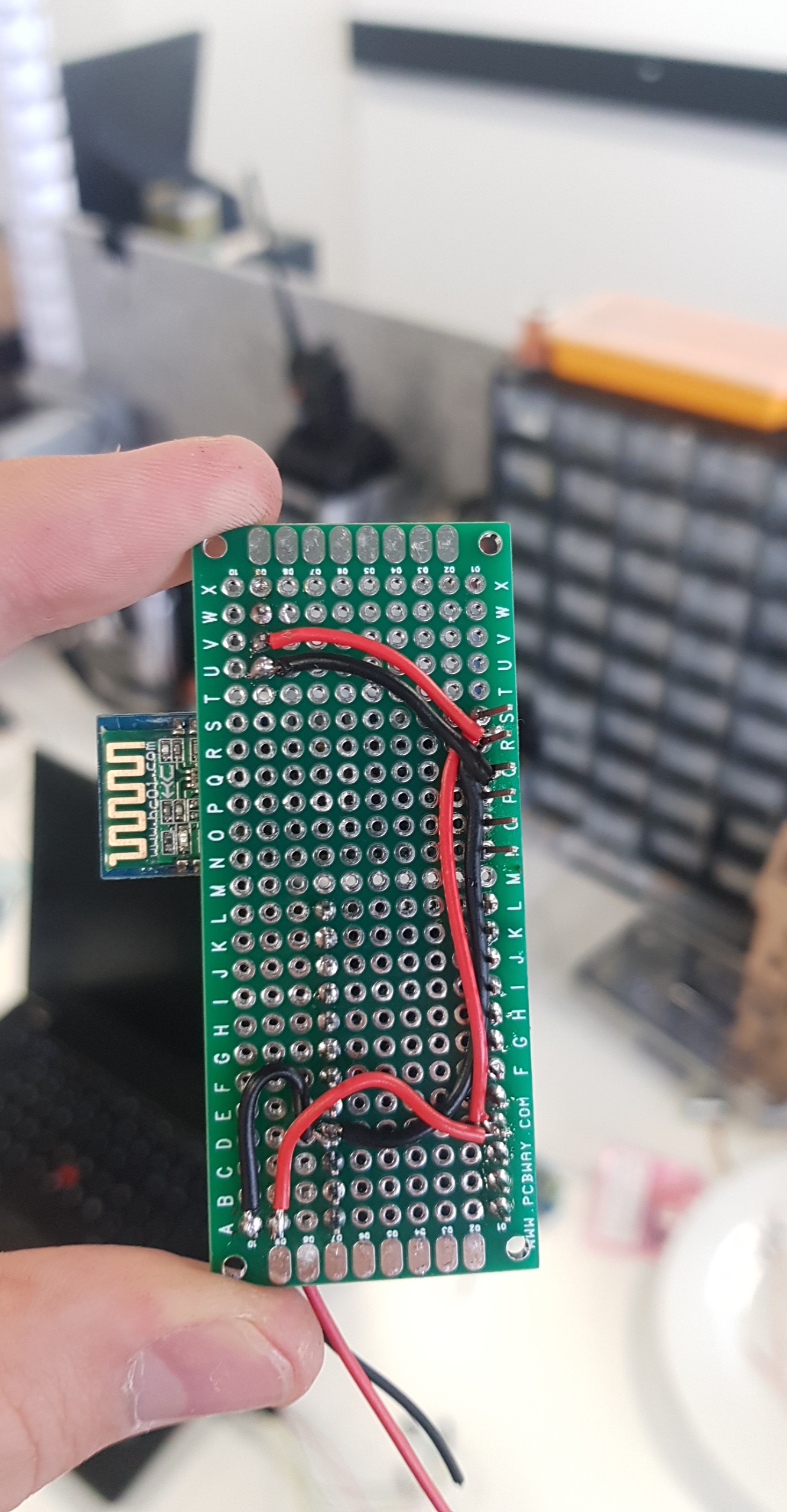
This step will require a few connections and some patience however it is quite straight forward.
NOTE: you can also perform this step on a regular breadboard without soldering however it will render your final product a little less portable.
Placement:
Components for this step:
- Arduino
- BT Module
- 3 Male Header Pins
- Wire
We must place the flashed Arduino and the Bluetooth module (HC-05) on the breadboard in any orientation we see fit. Ensure that the breadboard you are using does not group and bridge rows of pins. On the PCB-Way breadboard I used, each pin was independent.
Solder the following pins together:
Wire Out --> Arduino --> BT Module --> Header Pin
Red Wire --> VCC --> VCC --> Middle Pin
Black Wire --> GND --> GND --> Bottom Pin
Note: there are 2 GND pins on the Arduino, you can use either.
The final image depicts where I have soldered a single black and red wire to the right of the Arduino for the power connection.
Assembling the Board (Signal Wiring and Testing)
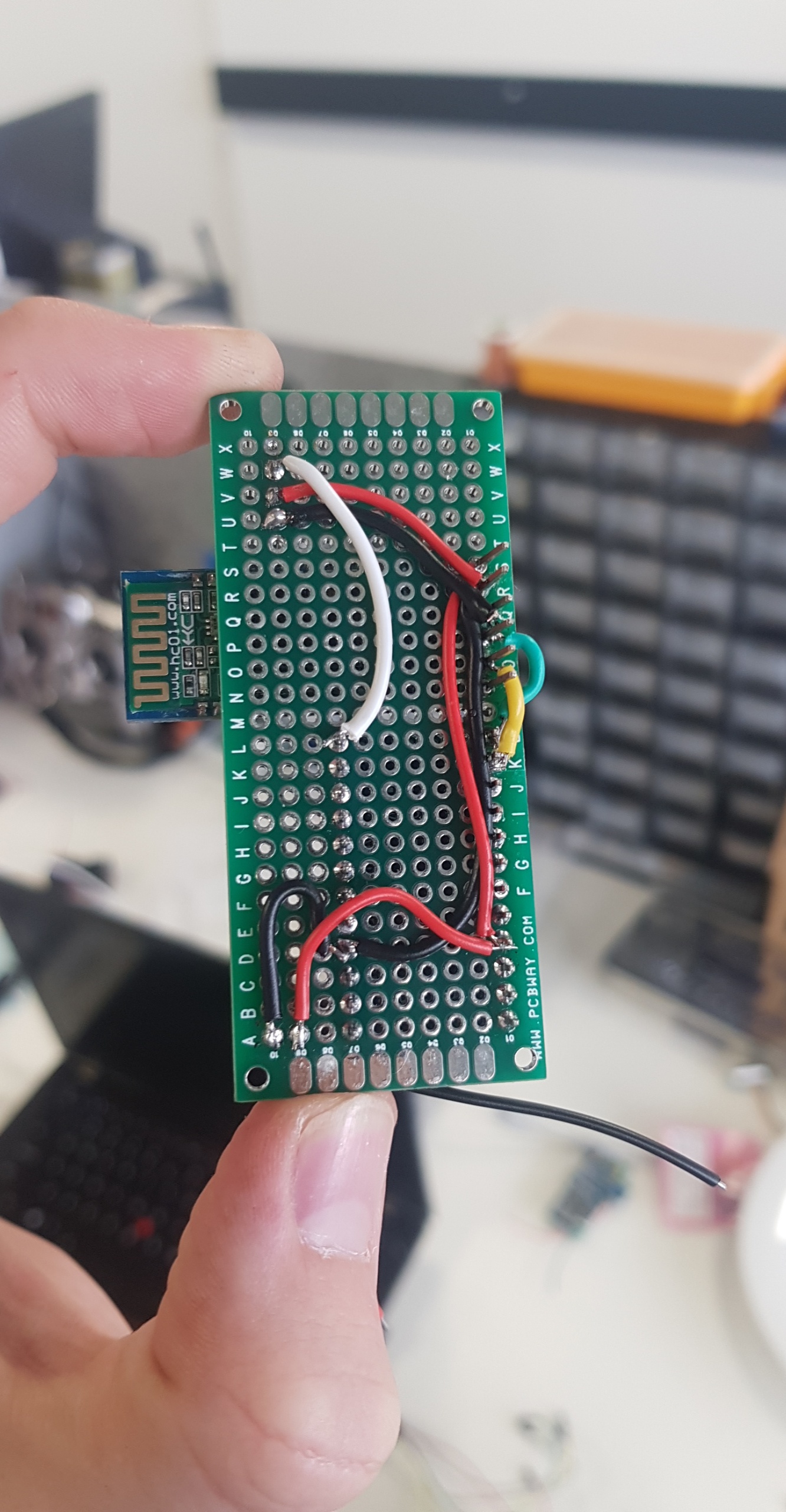
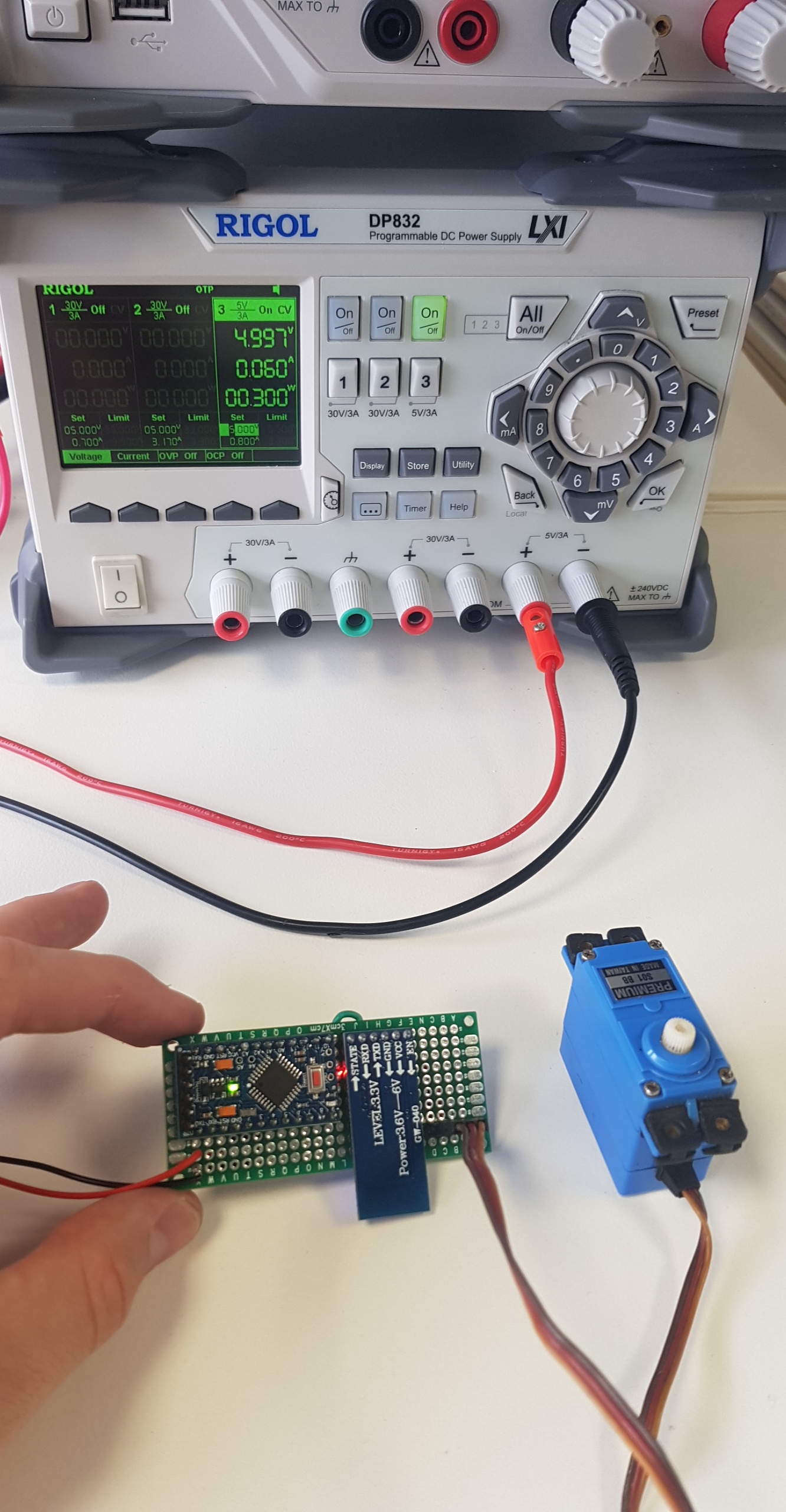
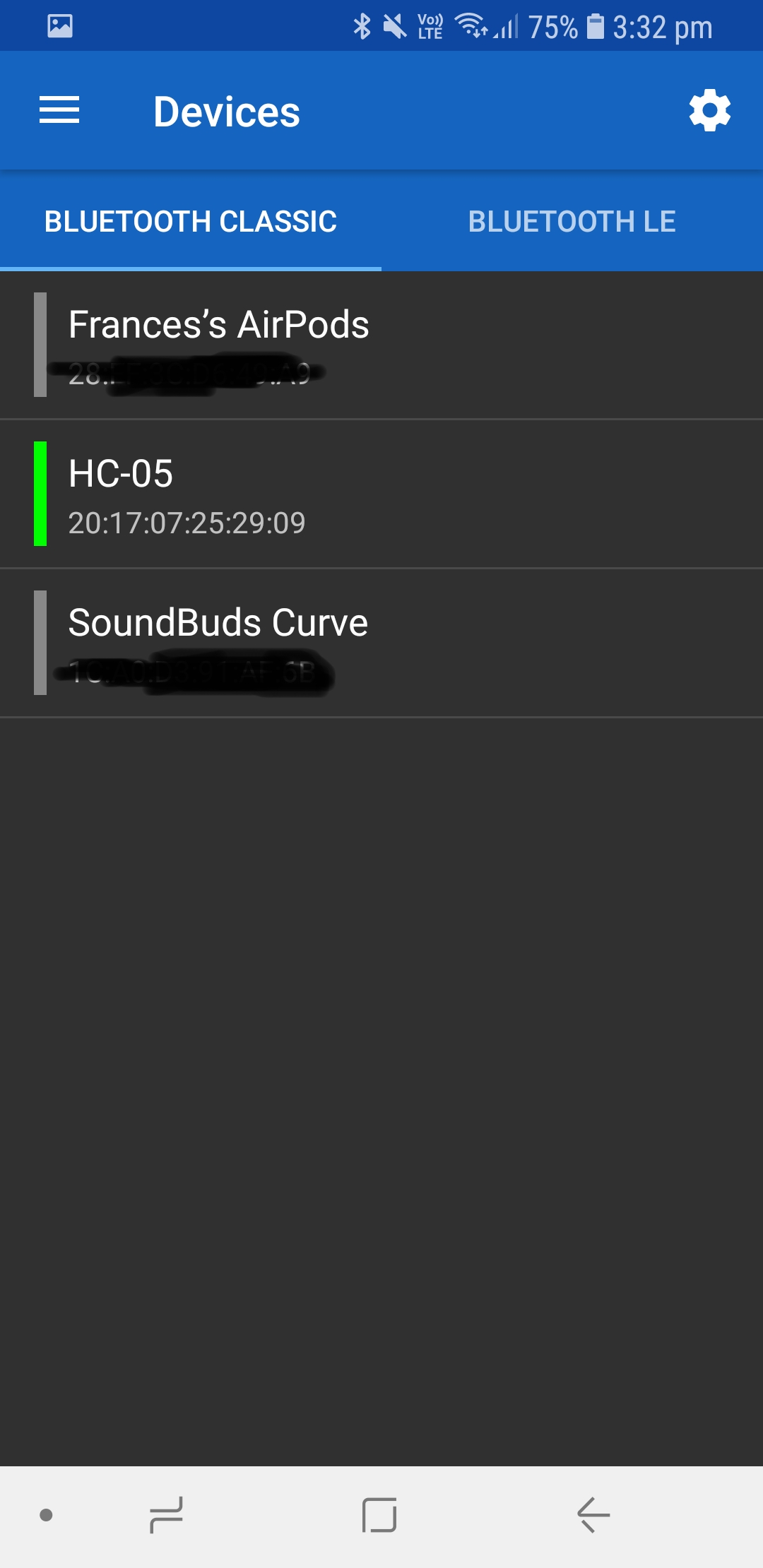
Signal Wiring:
Now we must run 3 more wires. As per our code the signal to the Arduino is on pin 9 and our serial communication with the BT Module is on pins 10 and 11.
Solder the following pins together:
Arduino --> BT Module
Pin 10 (D10) --> TXD (Green Wire)
Pin 11 (D11) --> RXD (Yellow Wire)
and for the signal to the servo we solder as follows:
Arduino --> Header Pin
Pin 9 (D9) --> Top Pin (White Wire)
Finally you can Plug in your servo motor to the header pins. They generally have 3 pin female header coloured Brown, Red and Yellow.
The Brown is Ground, Red is VCC and Yellow is Signal. Ensure the plug is on the header with the Yellow pin plugged into the top.
Testing:
You can now hookup your device to some power to confirm it is running!
5V .5A should be fine for this test, if you don't have a bench power supply you can continue through the steps and test after you have added the battery pack.
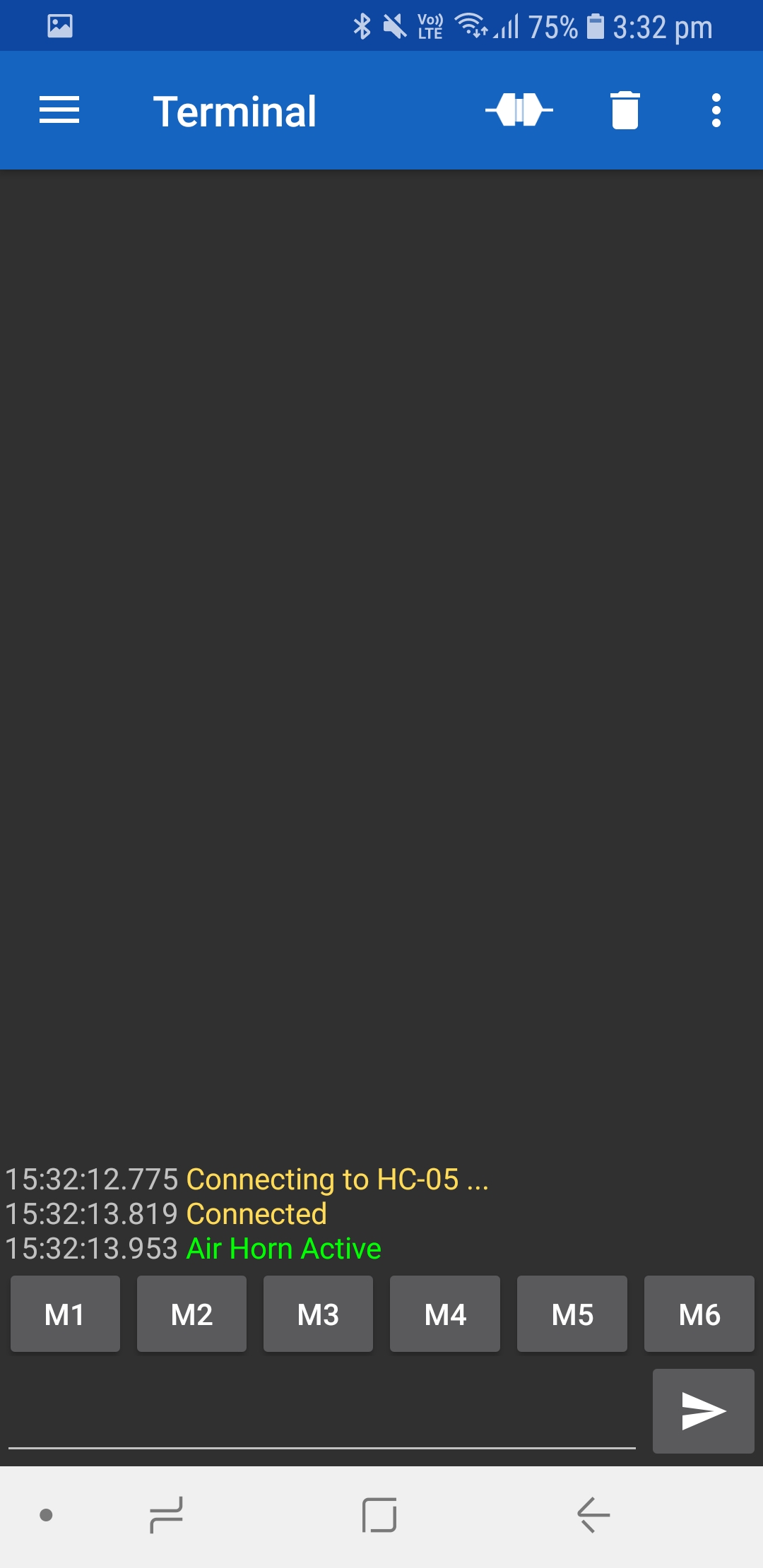
To test simply power on your device until the BT Module blinks and then scan for 'HC-05' which is the default device ID. Pair with the password '1234' (sometimes '12345' depending on the manufacturer) and install a Bluetooth serial APP.
I highly recommend 'Serial Bluetooth Terminal'. Click the hamburger menu in the top left and click on devices.
Ensure that HC-05 is highlighted green and then click back to the terminal.
Click the dual plug button next to the bin icon in the top right to begin the serial connection.
You should be greeted the serial printing out 'Air Horn Active' on a successful connection.
Send '?' to pull the menu or the numbers 1 through 4 and your Servo should begin to move.
NOTE: If you are having issues Troubleshooting is on the last step! Also feel free to comment issues and I can provide assistance.
3D Printing the Parts and Assembly
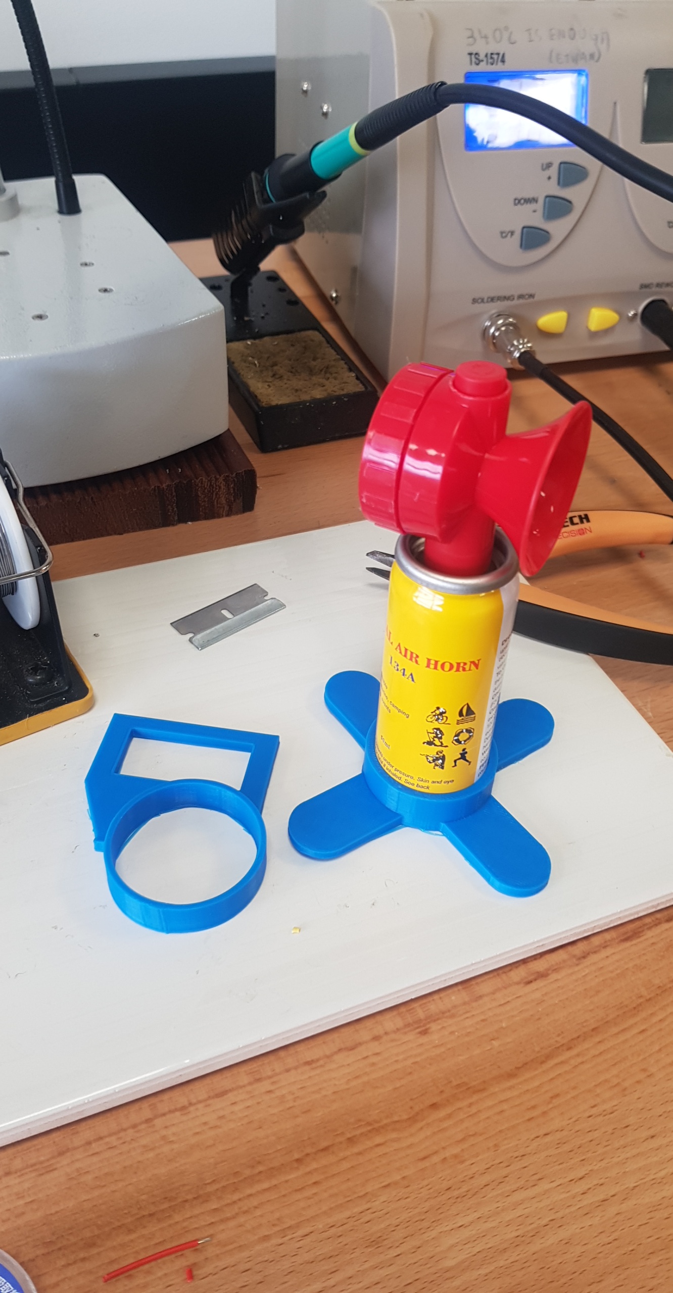
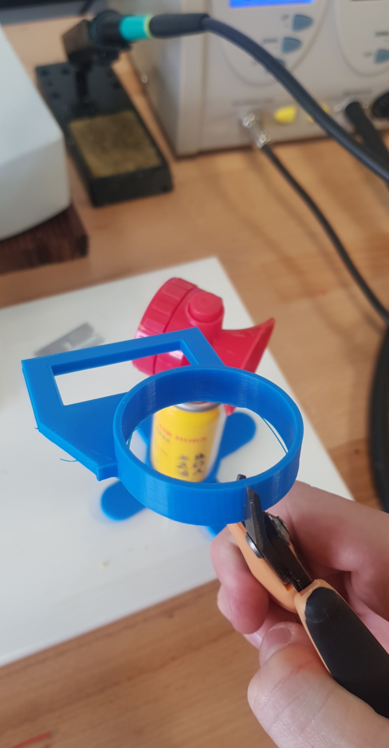
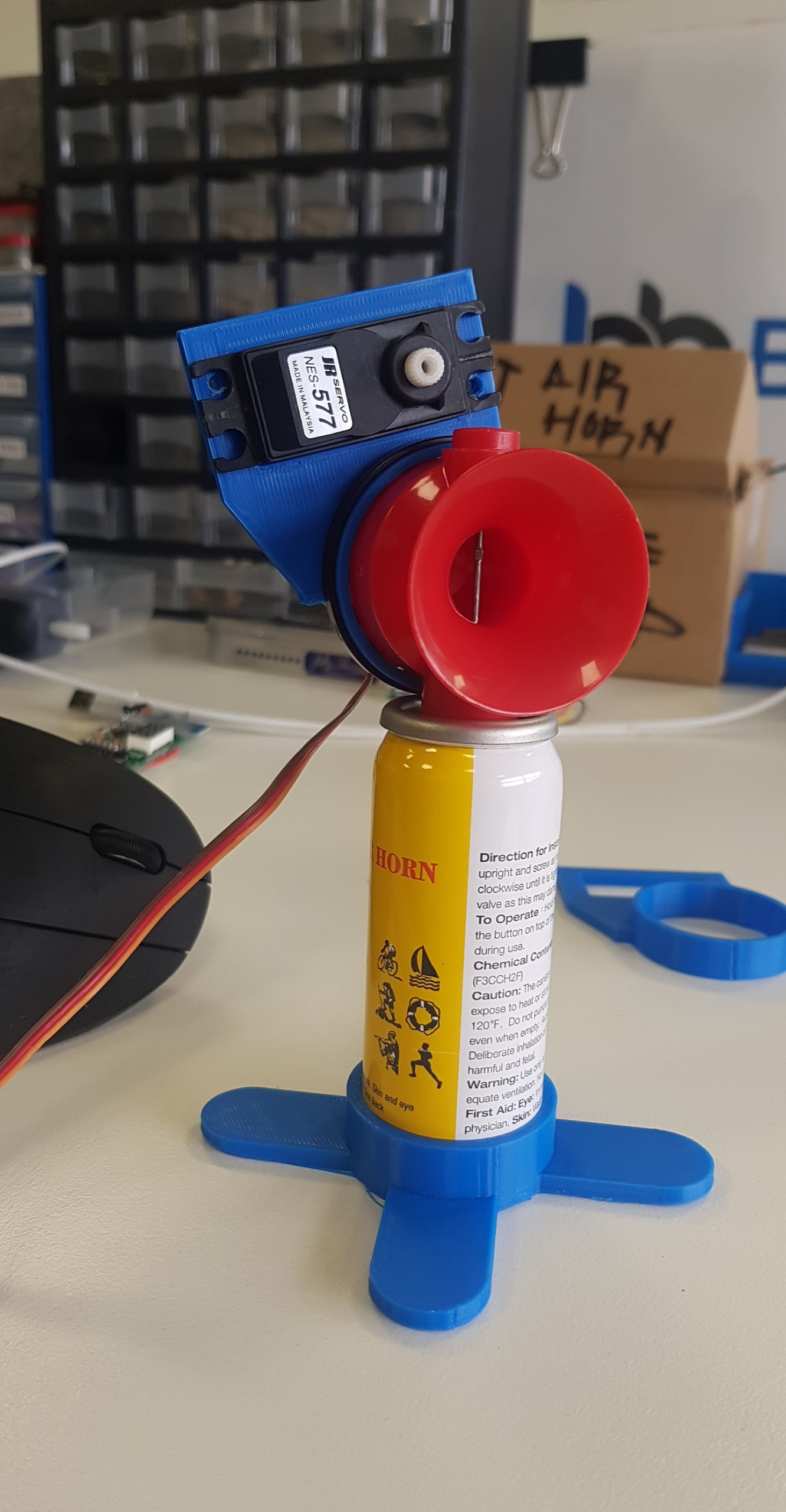
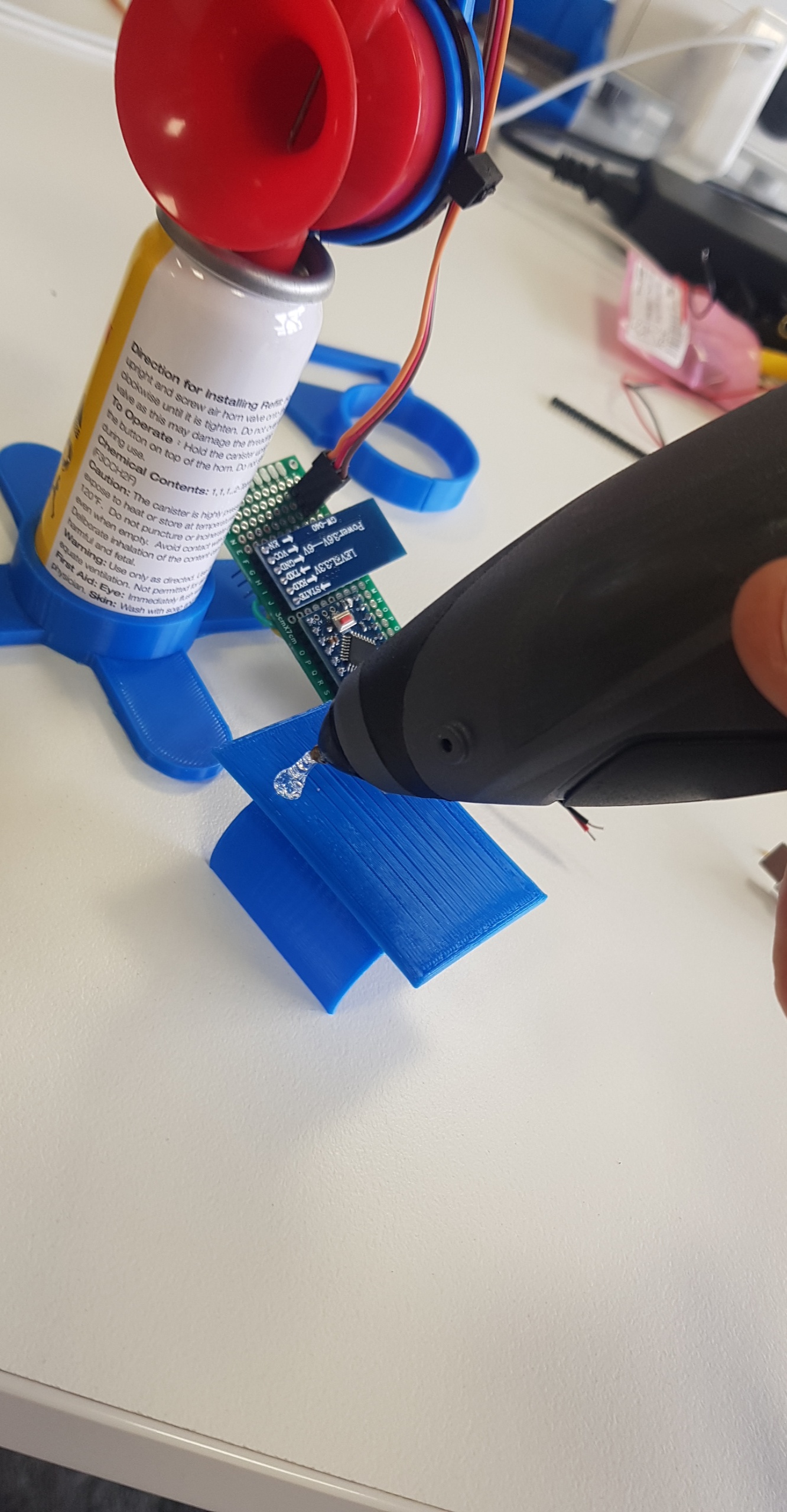
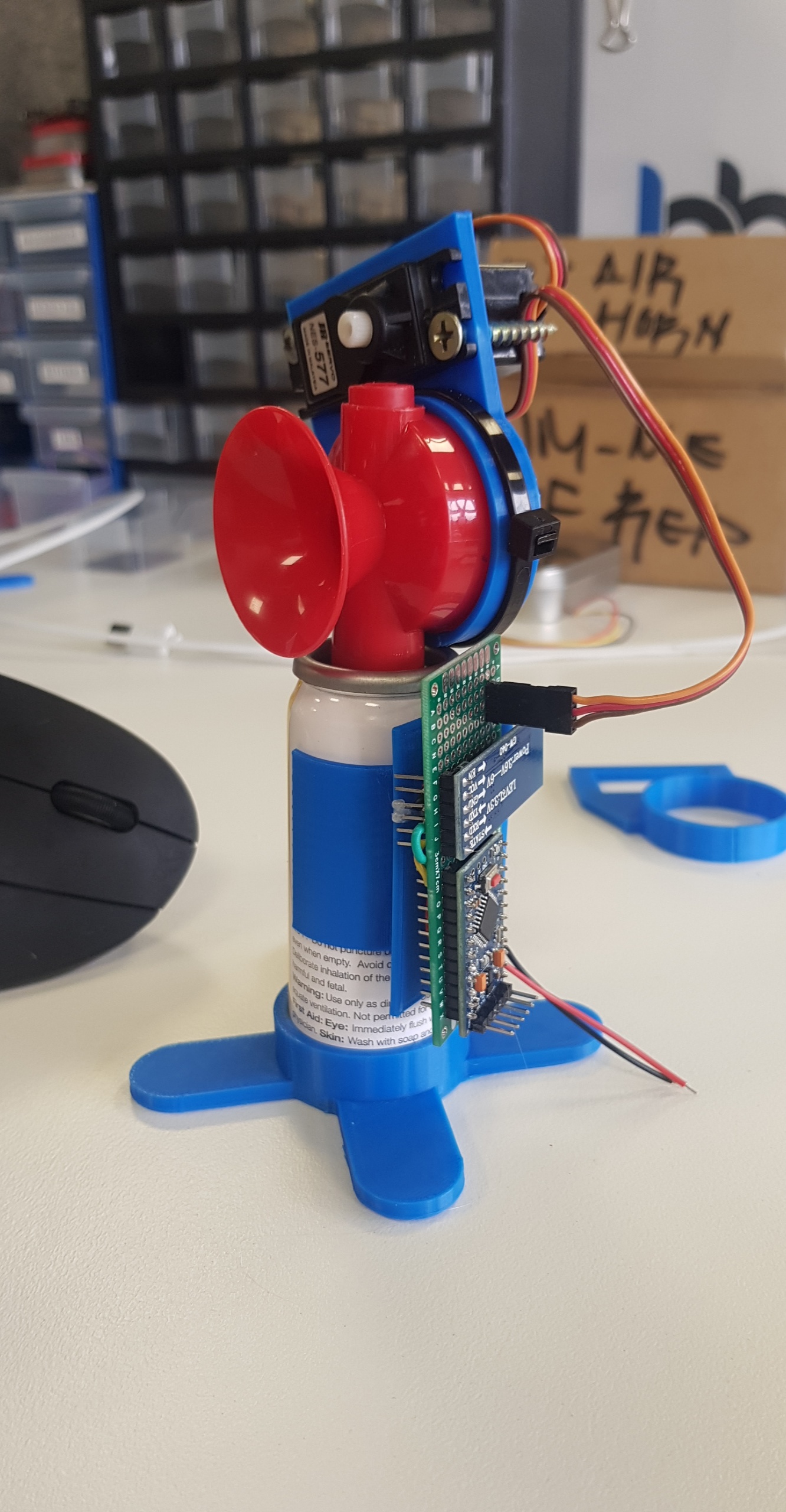
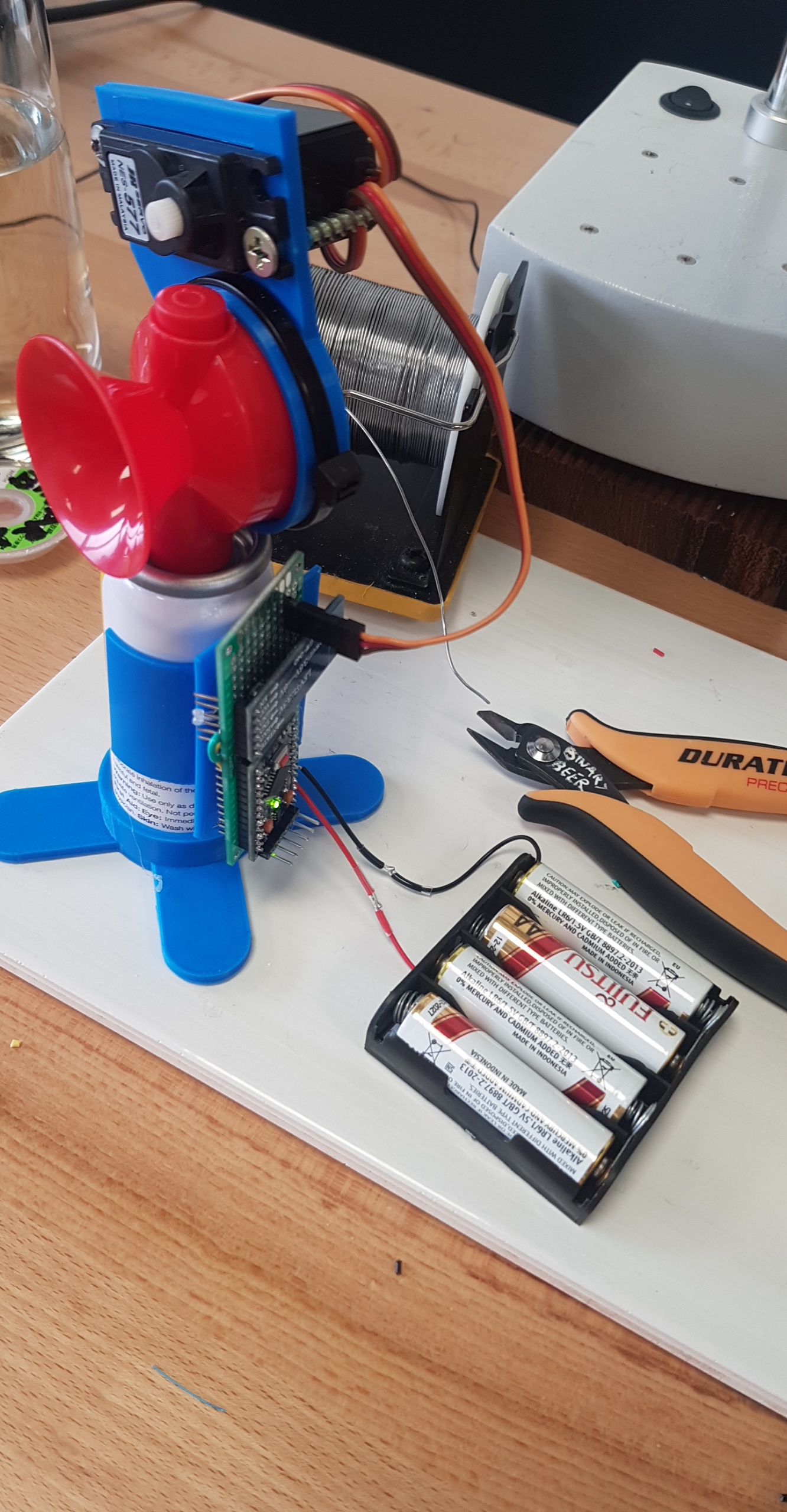
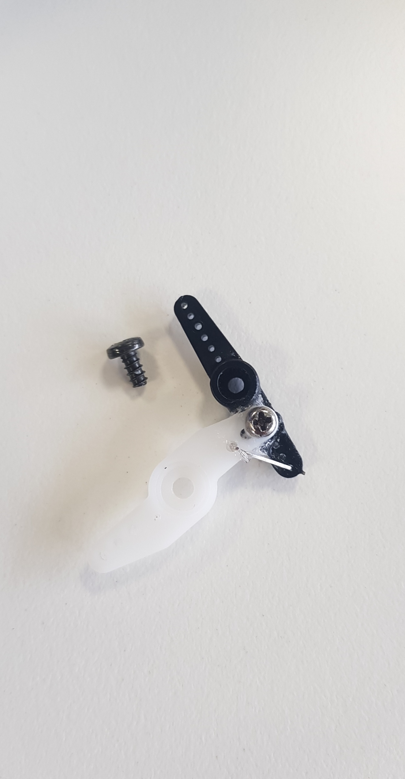
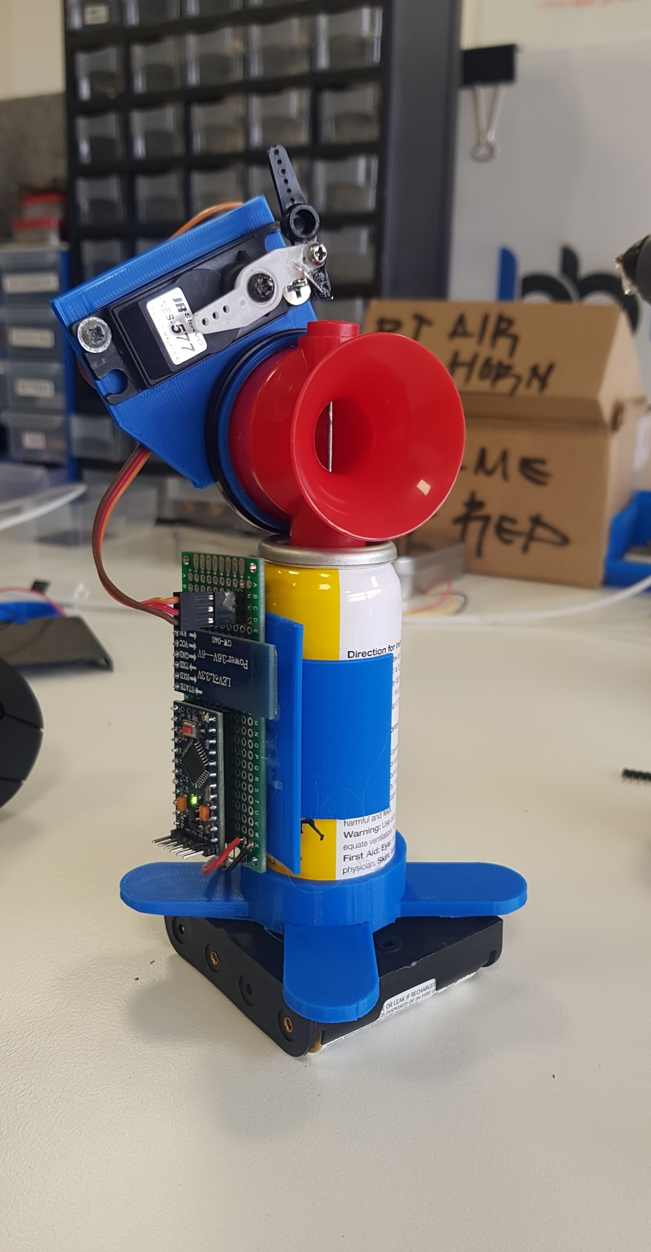
Now for the easy part. I have included the STL files HERE however most 3D printers are different.
- No model will require supports if they are oriented as per the final photo on a printer bed.
- Your printer settings will be determined by your material used however it is suggested that you opt for a moderate fill method for your print. Weak fill will allow the brace to flex and not enough downward pressure will fail to actuate the horn.
- (weak infill = flex = no horn = failed project)
Assembly
The base print easily snaps onto the bottom of your air horn canister, likewise the side PCB clip should snap to the side of the horn.
The servo mount is also quite easy to snap on. For added stability I suggest cutting the circular horn mount and zip tying it to the horn as per the attached photos. This will limit its ability to slip particularly with how much force is required to actuate a full canister. it is recommended that you run some screws through the servo but it isnt required as the 3d print should fit the servo rather snug.
I used 2 wood screws that were far too big to seat it in but you could also glue it the choice is yours!
You can now attach the double sided servo arm with the provided screw. I ended up super gluing another servo arm from a smaller servo to act as a 'finger' however it was completely unnecessary as there was enough torque from the straight arm alone.
Follow up by hot gluing the PCB you tested to the pcb mount (you can also screw this in but hotglue is always the easy way out) and clip it onto the horn.
Then you can solder the battery clip to the leads you soldered to the board for power.
NOTE: As per the data sheet the regulators on these boards run up to 16v input voltage so 4 fully charged AA batteries will be fine in this configuration.
Finally you can wrap those wires in tape or heatshrink them so they dont short out and for added stability you can glue the battery clip to the feet of the bottom stand.
The images in this step should cover this assembly. Ensure you have viewed them all.
GET TOOTING!
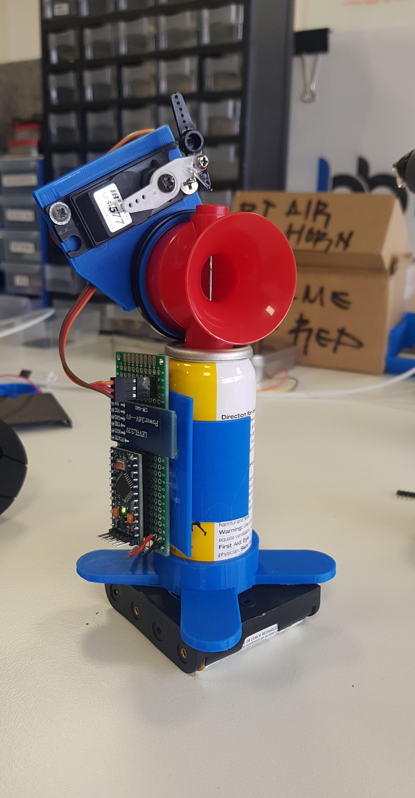
Signaling a race?
Planting it under your colleagues desk?
Just really love horns?
Well now the power is in your hands! (provided you are in BT range)
You are now fully equipped to toot 'till your heart's content. Be responsible as these horns are seriously loud for their size also try not to sound it near animals and be respectful of your neighbors (or don't I'm not a cop).
Optional Extras + Troubleshooting!
Optional Extras:
Super Cap: If your device doesn't actuate the horn but presses against the button and restarts you may not have enough current. Firstly change your AA batteries to brand new ones but you may also add an inline capacitor to the build. I had a few laying around and placed them inline with the power lines as per the image attached.
Voltage Meter + On/Off Switch: You can also insert a power switch to turn your project on and off by adding it inline with the main voltage line on the common port of the switch and the vcc of the circuit to the top pin. You can then use this circuit with the Volt Meter by adding the supply or red wire to the bottom pin of that switch. When it is turned off you will be able to read the voltage of the batteries. Put a momentary switch in series with the voltmeter to save power when it is turned off. Review images of my second board with this included.
Changing BT Name and Password: Use Techbitar's instructable here!
Troubleshooting:
Will populate as issues arise!