Blinking of On-board Led of STM32 Board
by anishkamal1011 in Circuits > Electronics
5363 Views, 1 Favorites, 0 Comments
Blinking of On-board Led of STM32 Board

Step 1:You'll need an STM32 black pill board and STM cube IDE. If you don't have the IDE already, you can download it from the STMicroelectronics website. Once you have the IDE installed, you'll need to set up your project.
Step 2: Create a new project
In the IDE, click on "File" and then "New Project." Select "STM32F401CCU6" from the "MCU Series" dropdown Click "Next".
Step 3: Give your Project a name and keeping else everything default click Finish.
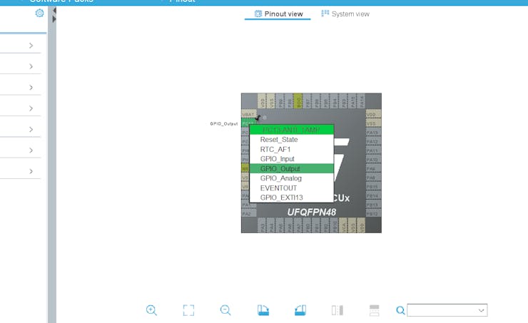
Step 4: Once that’s done, it will open up the pinout and configuration page. There it’ll display the physical shape of the MCU, and the pins and pin names. This is where you can set individual pins to different default values, and the IDE will use this info to auto-generate setup code. In our case, we want to just left-click the PC13 pin, and click “GPIO_Output”. This pin is the pin connected to a user-controlled LED on the black pill. If you look on the black pill, you can see the LED we want to control, and see it has C13 next to it. We can set other pins to use more of the black pill board, but for now, that’s all we need to do.
Step 4: Write your code
Now that your project is set up, it's time to write your code! Open the "main.c" file and enter the following code:
This code initializes the HAL library, enables the clock for GPIOC, and sets up the onboard LED (connected to pin 13) as an output. The while loop toggles the LED on and off every second.
Step 5: To have the IDE generate code, click the save icon, or hit ctrl+s to save the configuration. It will ask if you want to generate code, and then ask if you want to open the code perspective. Click yes to both.
Step 6: Now the main.c file will be open in one of the tabs. Select it.
Step 7: Scroll down to the while(1) section. Here we can add our code to turn the PC13 pin on and off.
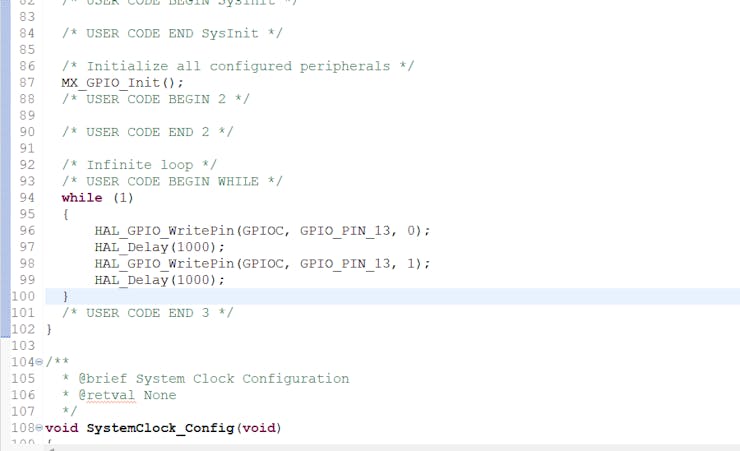
So the final code inside the while loop, for a simple blinking code using the STM32CubeIDE with STM32F401CCU6 is:
while (1)
{
HAL_GPIO_WritePin(GPIOC, GPIO_PIN_13, 0);
HAL_Delay(1000);
HAL_GPIO_WritePin(GPIOC, GPIO_PIN_13, 1);
HAL_Delay(1000);
}
Now that your code is written, it's time to build and run your project! Click on "Project" and then "Build All." Once the build is complete, connect your STM32 black pill board to your computer via USB and click on "Run" to load the code onto the board.
You've successfully blinked the onboard LED using HAL programming.
Supplies
In this Task, we have used a BlackPill STM32F401CCU6 board and A type-C cable .
The STM32F401/F411 Black Pill Development Board is an updated version of the popular F103 based Blue Pill. This newer version features a more powerful Core-M4F based ARM CPU. Both F401 and F411 processors supports DFU bootloader.