Blinking Led Using Arduino(TinkerCAD)
by anuragkar in Circuits > Arduino
1664 Views, 0 Favorites, 0 Comments
Blinking Led Using Arduino(TinkerCAD)
.png)
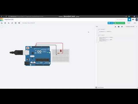
HI! This instructable is going to be a pretty basic one. Here I will be going to show how to use TinkerCAD to blink an Led using Arduino.
TinkerCAD is a pretty useful software when it comes to testing your code quickly and is very handy for those who are new to microcontrollers. The good thing about it is that you will never damage real electronics while testing as everything runs on the virtual world. But you may face issue while compiling some codes that will run quickly in real-world but gets struct in the virtual world.
Opening Tinker CAD
_LI.jpg)
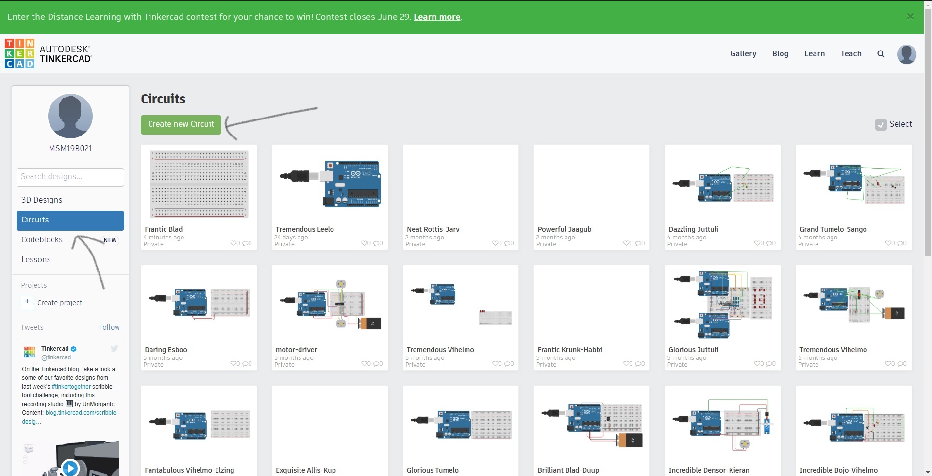
You can directly go to link: https://www.tinkercad.com/dashboard or may google tinker cad and browse through the website.
Then you have to log in to your account and you will see the dashboard. Click on Circuits on the left side of the screen. Proceed to Create new Circuit button.
The Components
.png)
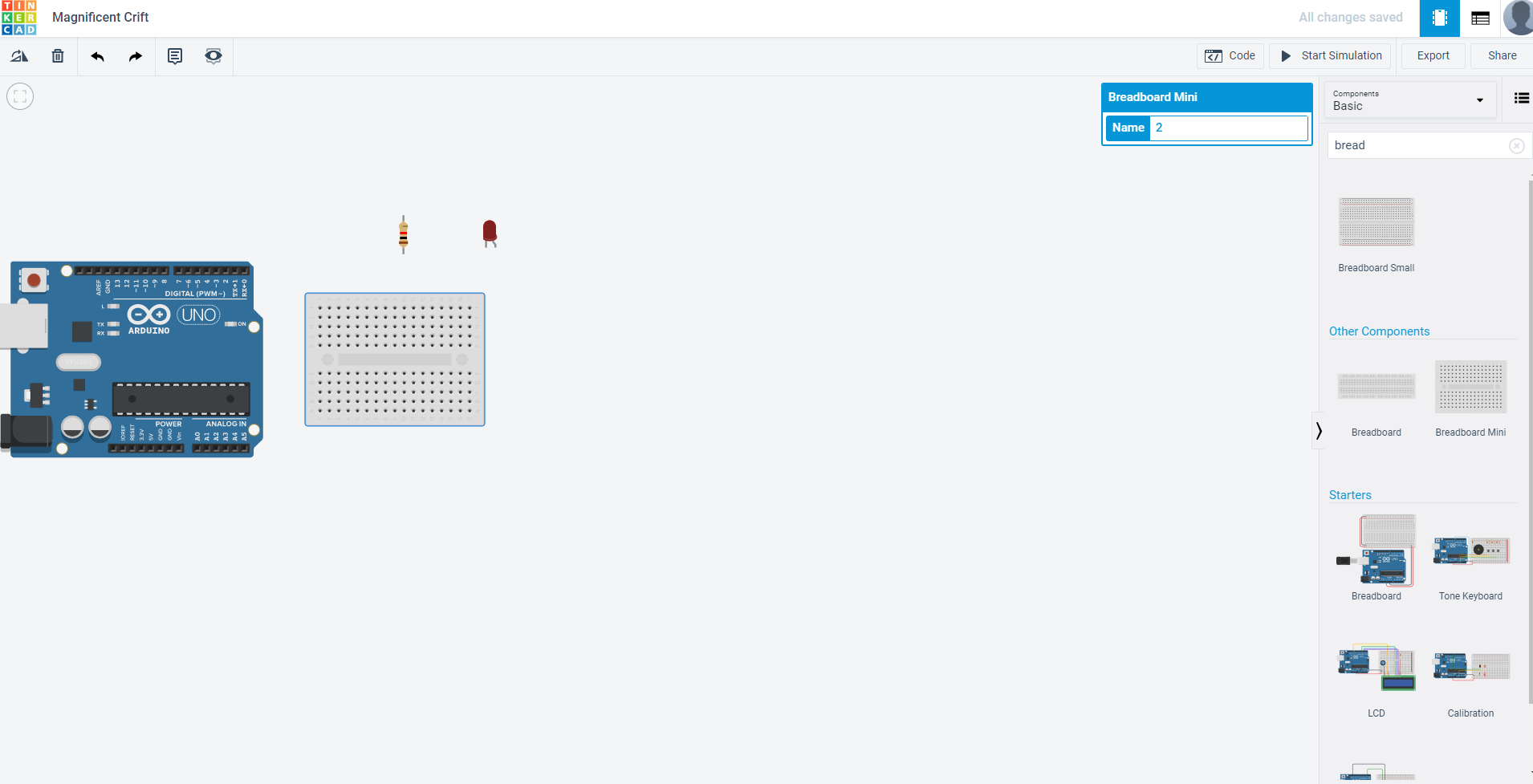
Now browse the list of components and drag the components that have been listed here.
1)BreadBoard Mini
2)Arduino Uno R3
3)LED
4)Resistor
Placing the Components
_LI.jpg)
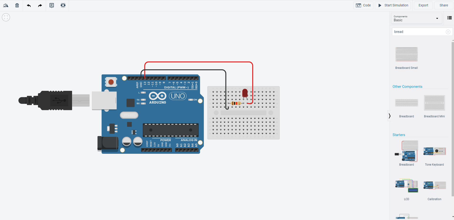
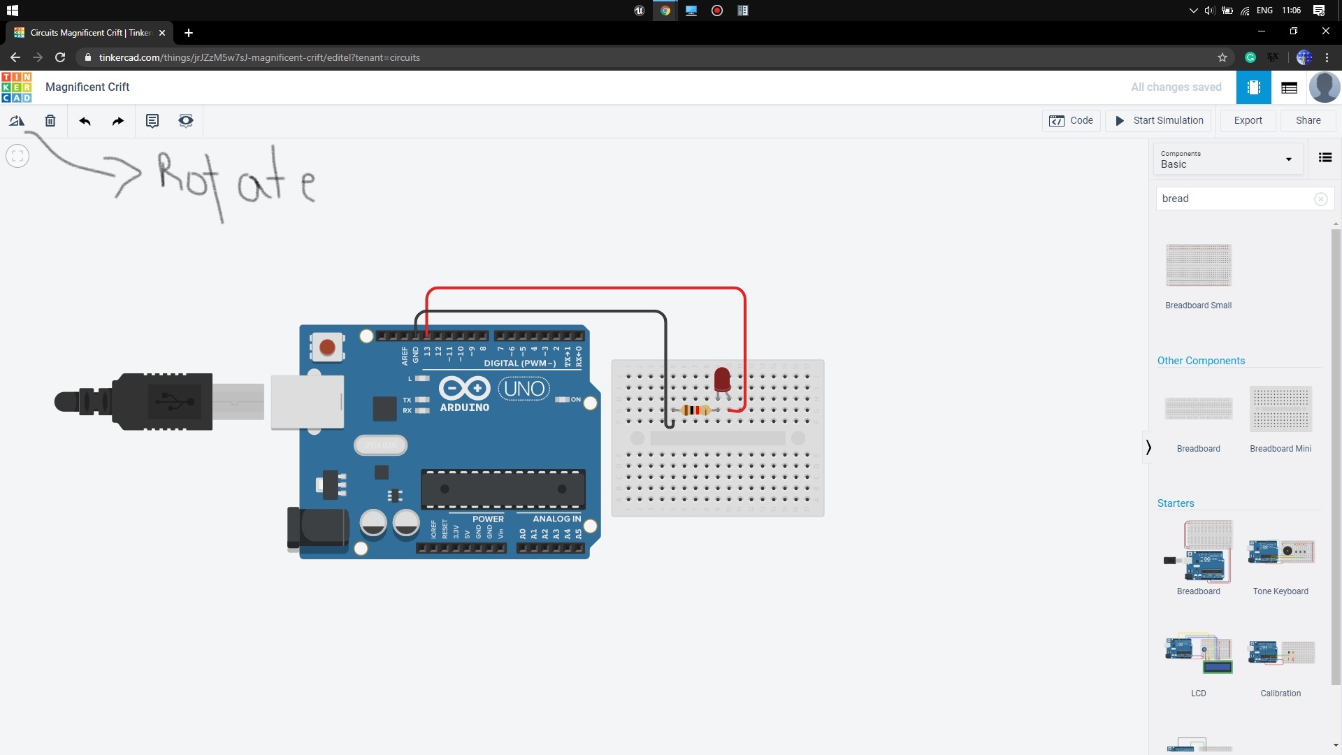
Now we have to connect all the components as per requirement. Place the LED anywhere in the mini breadboard. Remember the bent terminal of LED is the longer terminal and hence the positive terminal. Place the resistor to the next row of the LED negative terminal. Rotate it before placing it.
Now drag a wire from pin13 of the Arduino by clicking on it. Connect the wire to the next row of the LED on the breadboard. Similarly, drag a wire from the GND(ground)pin of the Arduino and connect to the next row of the resistor. You can change the color of the wire by clicking on the wire and selecting the color from options appeared.
Choosing a specified set of colors will help us to debug a complex circuit and hence keep it a practice is beneficial.
Testing the Circuit
.png)
.png)
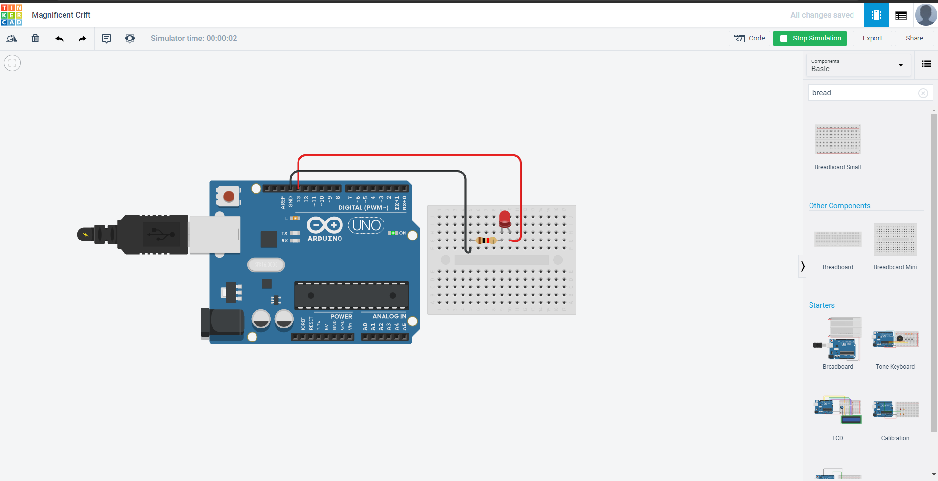
Now click on the simulation. You will notice the LED starts to blink. Now this is because the led is already connected to pin13 and it has the default code of blinking with a delay of 1 second.
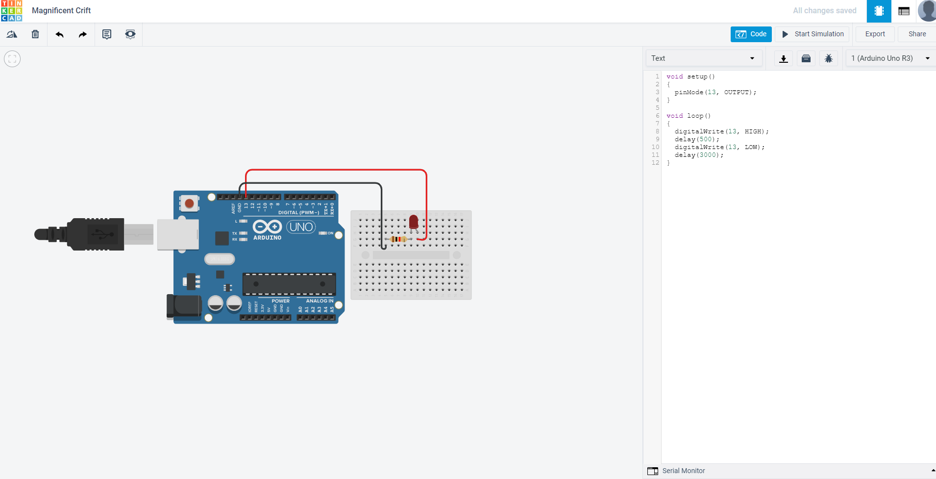
Now we can manipulate the blink by clicking on the Code button and putting our own blink code there.
On opening the Code click on Text by selecting the drop-down menu on the left side. You will notice the default code is written. Changing the delay value will give you different blinking styles.
If there is any issue please let me know.
Demo!
