Blinking LED and Low-Code: ESP8266 and Hackeet Basics
by Hackeet-Official in Circuits > Arduino
525 Views, 0 Favorites, 0 Comments
Blinking LED and Low-Code: ESP8266 and Hackeet Basics
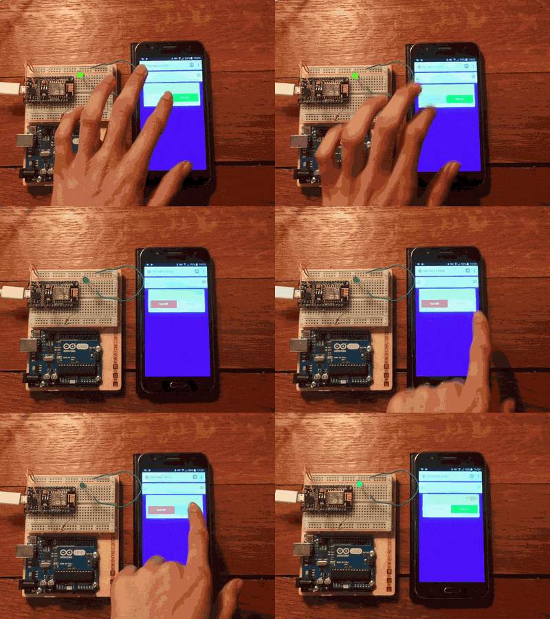
Blink an LED from your smartphone without any coding thanks to Hackeet, a private-by-design low-code application development platform.
Things Used in This Project
In order to build this project, you will need the following :
Hardware components
- Raspberry Pi 3 Model B (1)
- NodeMCU ESP8266 Breakout Board (1)
- Breadboard (1)
- LED (1)
- Resistor 221 ohm (1)
Software apps and online services
- Arduino IDE
- Hackeet
Install Software
Install the latest versions of Hackeet and of the Arduino IDE on your Raspberry Pi.
You need a license to start Hackeet. You can get a free one by following the instructions on the this page : Hackeet : Get Started
At last, install the Hackeet package for Arduino and ESP8266 that you can download here (click on the Pin node for example to get the installation instructions).
You can find all the information about installing Hackeet and component packages on this page.
ESP8266 Configuration
Before using Hackeet with your ESP8266 or your Arduino board, you need to configure it first.
- Start the Arduino IDE
- Within the Arduino IDE, open the file installed on your Raspberry Pi at location /home/pi/Hackeet/Arduino/HackeetSketch/HackeetSketch.ino.
- Edit the Settings.h file and enter the appropriate configuration for your hardware (Esp8266 or Arduino, WiFi or Ethernet connection). Don't forget to set the right credentials for your device to connect to your local network when using Wifi. Refer to the Code part of this tutorial to get an example of valid Settings.h file.
- Upload the sketch on your ESP8266 or Arduino UNO board
- In the Arduino IDE, click on the Serial Monitor icon (usually the one at the upper right of the main toolbar of the Arduino IDE) to get the IP address and MAC address assigned to your device. Upon successful configuration, you should see connection details like the following ones :
------------------------------------------------
Hackeet Virtual Shield for Arduino SSID: ?
IP Address: 192.168.0.13 signal strength (RSSI):-65 dBm
MAC: C3:B0:14:94:1:40
------------------------------------------------
If you are not very familiar with the Arduino IDE, you can refer to a more detailed installation guide here.
Build the Circuit
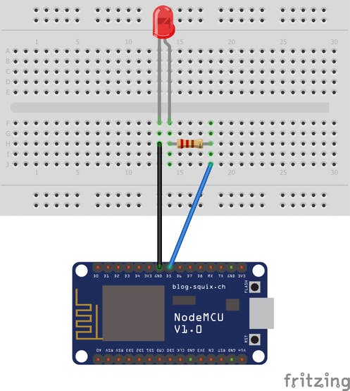
Great ! Your ESP8266 device is now ready. So now, let's build the circuit.
- Connect one end of the resistor to the digital pin D5. Connect the long leg of the LED (the positive leg, called the anode) to the other end of the resistor.
- Connect the short leg of the LED (the negative leg, called the cathode) to the GND
Here you are ! You are now ready to start coding!
Build the Web Application - Start Hackeet

Coding with Hackeet
Before going any further, some words about coding with Hackeet.
Hackeet is a low-code visual programming tool that allows you to connect hardware or software components together to create Web Applications and Micro-services for Raspberry Pi, Windows and Arduino / ESP8266 devices. Building an application with Hackeet is just a matter of connecting together nodes, which are elementary blocks in charge of performing actions such as sending an e-mail or moving a robot. Applications built with Hackeet run directly on your own hardware and thus preserve the confidentiality of your data. You can find additional information about used terms and concepts on this page.
If you want to go faster, you can download the application here and open it with Hackeet.
Let's begin !
Start Hackeet from the icon located on your desktop or from the Raspberry Pi main menu
Build the Web Application - Build Diagram
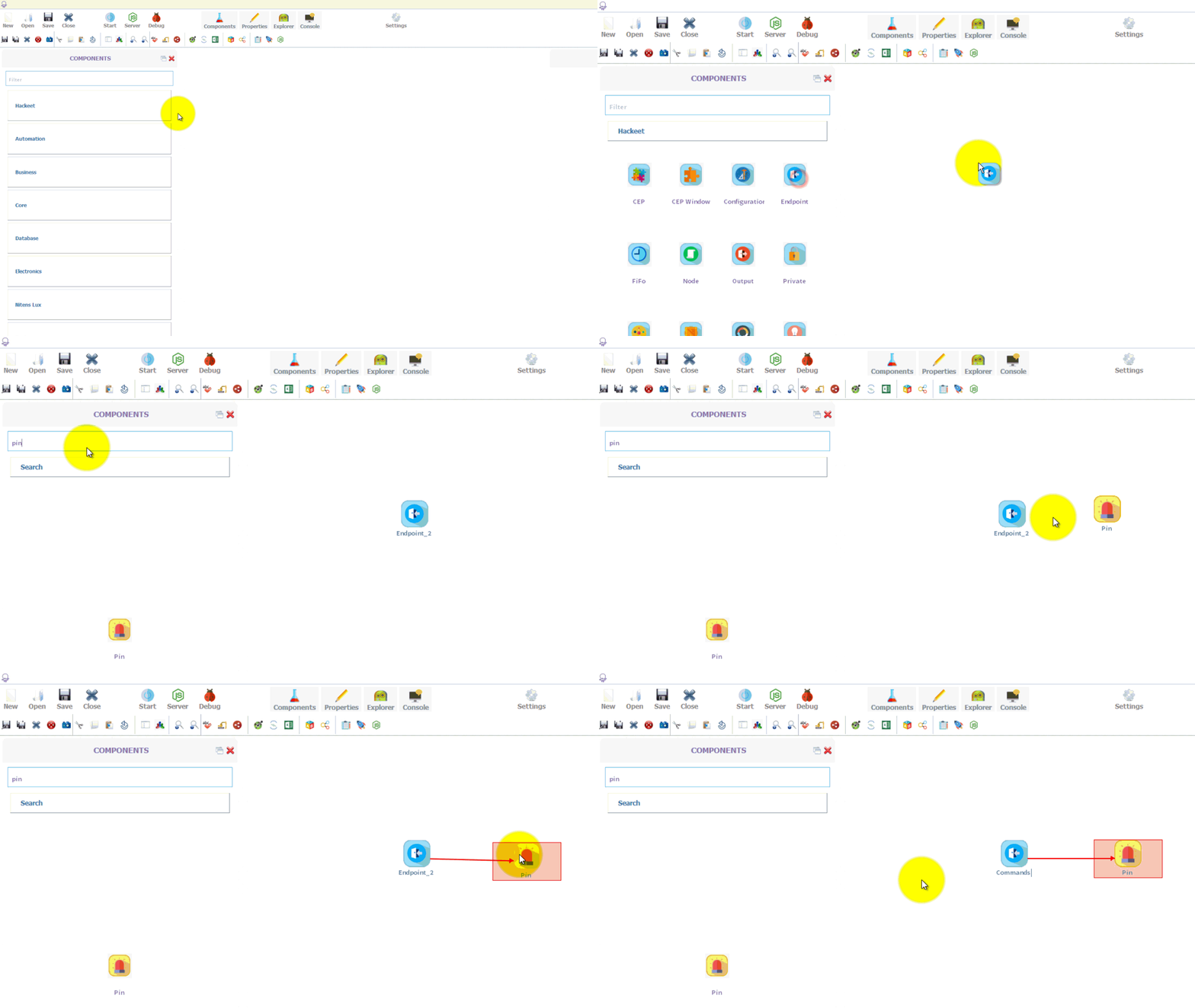
- Once Hackeet has started, create a new application by clicking the New icon from the main toolbar and save it.
- Select an Endpoint node and a Pin node from the Palette, drag them into the design view and connect them. To connect two nodes, just double-click on the first one (the Source node) while holding down the left button and release it on the second node (the Destination node) when the arrow turns green.
So, how does it work ?
As already mentioned, nodes in Hackeet are components that are able to carry out one or several actions. You have nodes to send or receive tweets from Twitter, perform automated phone calls with Twilio, publish data to MQTT servers, etc.... Endpoint nodes are no exception and their role is to receive inputs coming from users.
Nodes are able to exchange data through wires, i.e the arrows that connect them. When a node is "hit", it's to say when it receives data, it performs the action that it has been made for and then, may eventually propagate new data in its turn to the nodes it is connected to.
In we dig a little deeper into the details, when you build a web application with Hackeet, what you are actually doing is creating a REST API. In such a context, Endpoint nodes represent the endpoints of your API. If you have already tried to use or create web services, the concept of endpoint should sound familiar. For those of you for who it is not clear, let's say in a word that each Endpoint node added to your diagram when designing the application will result in an actual URL that you will be able to use to send data to your application when running.
You can specify data that are expected from users by adding attributes to Endpoint nodes.
In our case, we want the user to provide an information that specifies whether the LED has to be on or off. So we will add an attribute to the Endpoint node that we are calling to call led (name can be chosen freely but we are not very original).
When data will be received, it will be then forwarded to the Pin node though the wire that connects the two nodes together. At last, the Pin node will turn on or off the LED according to the value entered by user.
So, now that this is said, let's continue!
Build the Web Application - Change Endpoint Properties
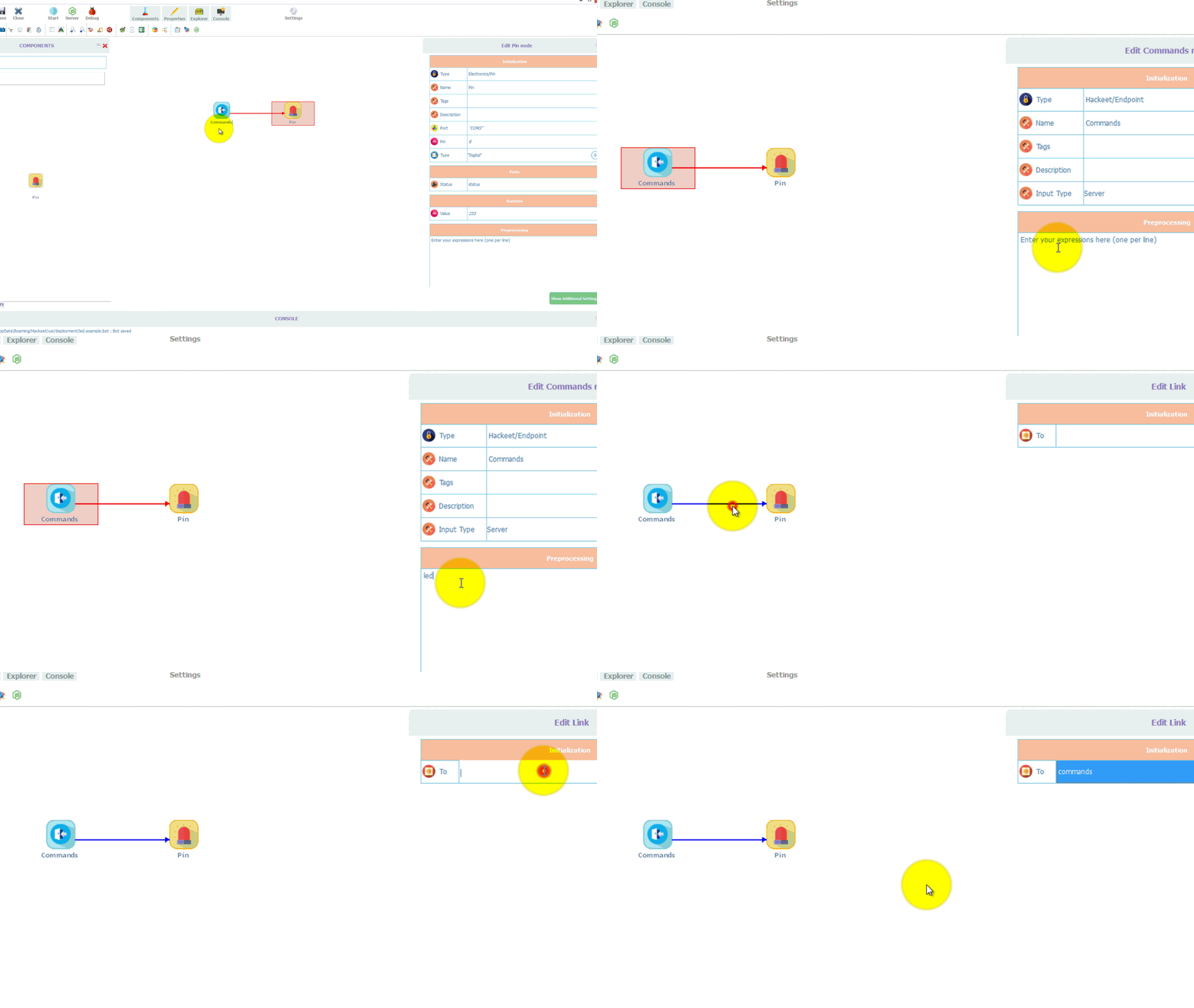
- Click the Endpoint node to edit its properties. Rename it to Commands and add the led property in the Pre-processing area. Rename the link between Commands node and Pin node to commands.
Build the Web Application - Change Pin Properties
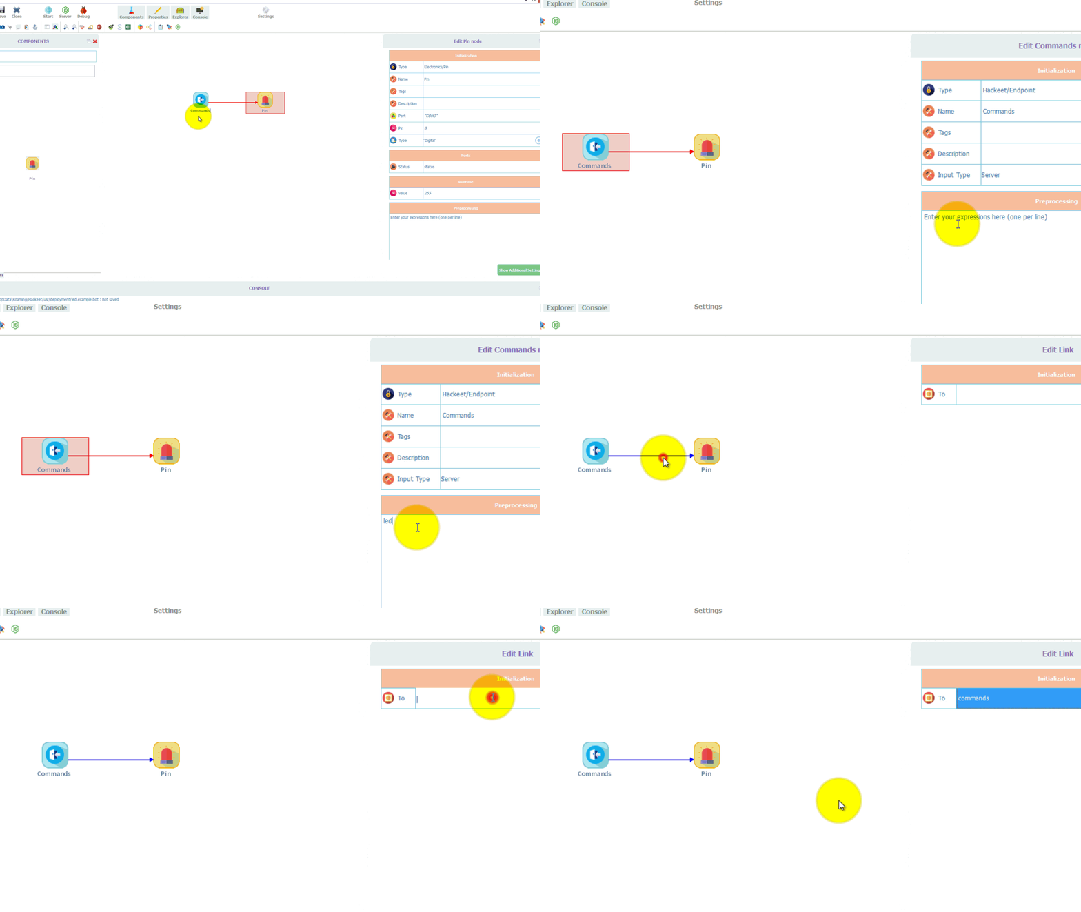
- Click the Pin node to edit its properties.
- Rename it to LED and specify the TCP/IP port and address of your ESP8266. Since the LED is connected to the D5 port of theESP8266, enter 5 for the Pin property. The Value property is the one that controls the state of the LED : if set to 0, the LED is off, is set to 1, it's on. Thus, in order to control the state of the LED from a smartphone or web browser, we must assign to the Value field the data received from the user and transmitted by the wire commands, and more precisely, we must use the commands.led field
Start the Web Application
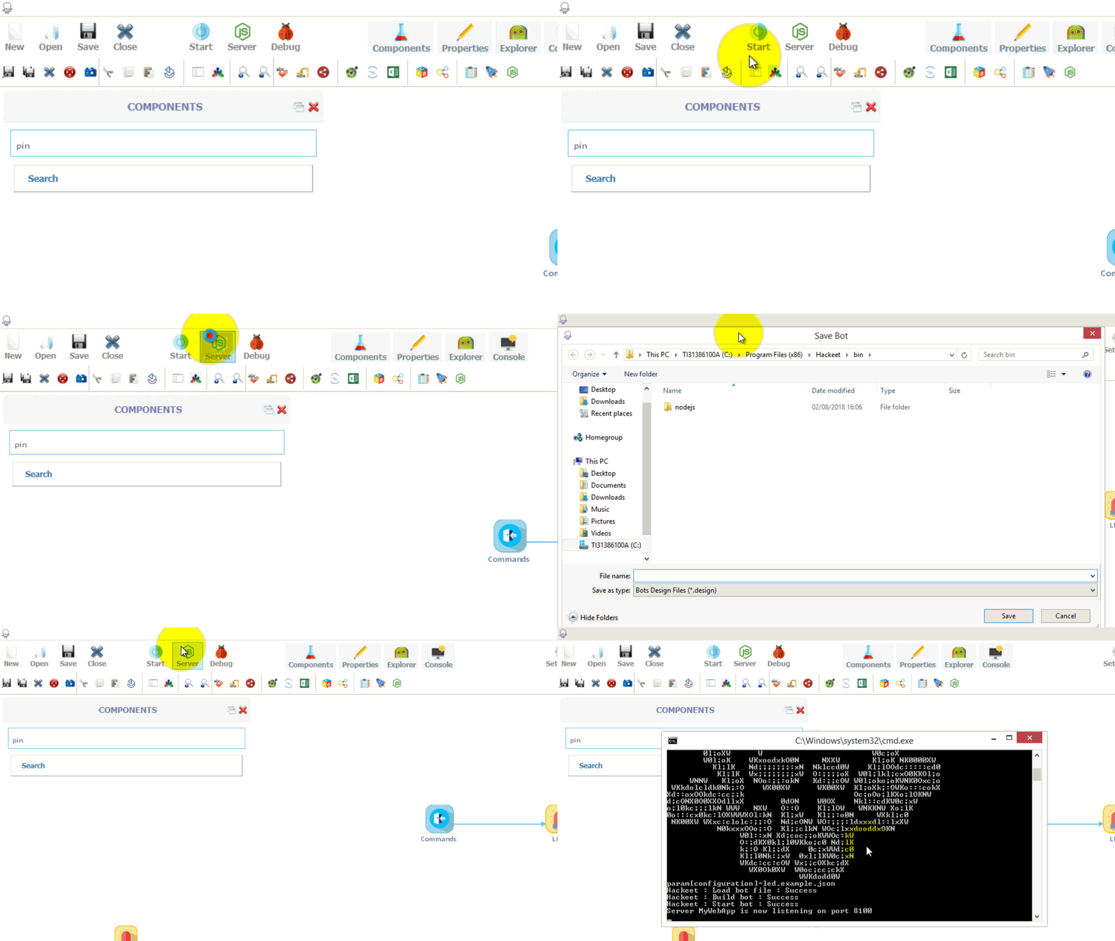
Start the Web application by clicking the Server icon from the main toolbar
Test the Web Application

Your server is now listening for incoming requests on port 8100 on your local machine.
- Open a web browser and navigate to the URL http://localhost:8100 on your local machine. Enter 0 or 1 to change the state of the LED (it can takes few seconds to start)
Customizing the User Interface
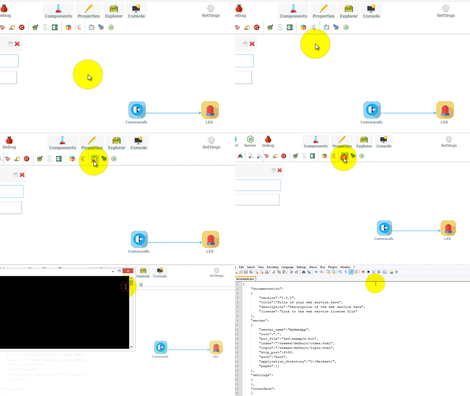
So good, so far ! Our web application is now up and running but it is not very appealing yet. Fortunately, with Hackeet it is possible to change the user interface using JSON configuration files. So let's do this !
Let's make our user interface a little sexier by replacing the very useful (but not very nice) input element of the form with a switch button.
- Edit the configuration file of your application by clicking on the Application/Server Settings icon
- Add the following JSON object to the screens part of the configuration file
{
	"id": "screen_1",
	"title": "The Switch Element",
	"widgets":
	[
		{
			"id": "widget_1",
			"io": "Commands",
			"field": "led",
			"type": "switch",
			"on": "Turn On",
			"off": "Turn Off",
			"label": "LED #1"
		}
	]
}
You can also directly copy and paste a complete configuration file from here.
If your application is still running, stop it and start it again as previously described to take into account the configuration changes you have just made.
Navigate again to URL http://localhost:8100/ from your browser on your local machine to check that input element has been replaced by a switch button.
Some Words About Configuration Files
Hackeet uses JSON configuration files to set parameters that may be required to start the application (for example credentials to connect to a database or a Web Service such as Twitter or Twilio) but also to define a default user interface for your application.
The user interface is defined within the configuration file as a collection of screens, each screen being itself a collection of widgets.
In the previous section, we have defined for our application a single screen which internal id is screen_1 and which have only one widget which internal id is widget_1.
As we want the user input to update led attribute of the Commands node that we have defined when building our application with Hackeet, within the configuration file, we have to set the io field to Commands and the field field to led for this widget. We then define the type of the widget (here, switch to have a switch button) and the labels for the on/off states.
Hackeet currently supports several kinds of widgets to build interfaces that you can explore here.
Next Step
Your Raspberry Pi is now running a server on port 8100 to allow you to turn on/off the LED. Since no data is sent to the cloud, if you want to use your smartphone to control the LED, you must first make sure that it is connected to the same network area as your Raspberry Pi. Once done, just connect to your Raspberry Pi on port 8100 from your favorite browser installed on your smartphone (for example, if the IP address of your Raspberry Pi is 192.168.0.3, just navigate to URL http://192.168.0.3:8100).
We have tried to show here a very basic application that can be made with Hackeet. If you want to have any further information about how Hackeet works and build more sophisticated applications for your ESP8688, Arduino and Raspberry Pi, do not hesitate to visit our website.