Blinking


The STM32 Black Pill, paired with the STM32CubeIDE, offers an excellent platform for learning embedded systems development. In this tutorial, we'll explore how to implement a sequence where three LEDs blink in various combinations. These combinations will include patterns such as 100, 010, 001, 110, and others, totaling nine distinct combinations. We'll achieve this using HAL (Hardware Abstraction Layer) programming, which simplifies low-level hardware access and configuration on STM32 microcontrollers. By following this tutorial, you'll gain hands-on experience in configuring GPIO pins, controlling LEDs, and creating custom sequences, laying a solid foundation for more complex embedded systems projects. Let's dive in and start blinking those LEDs in exciting patterns!
Supplies
- STM32 Black Pill
- Bread Board
- Male-Male jumper connector cables
- LED (3 nos.)
- C Type cable
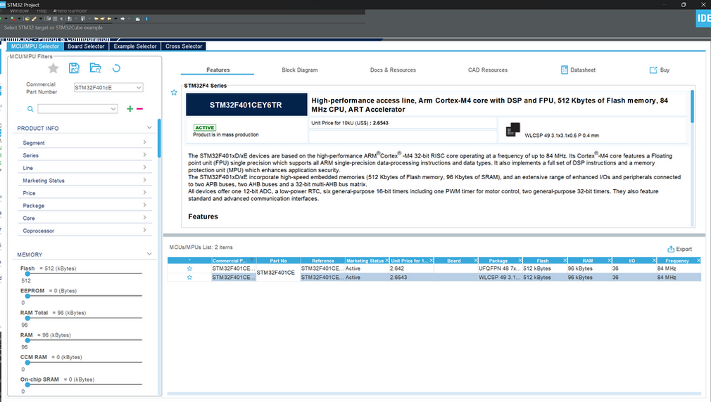
Making a New Project File in STM 32CubeIDE
GOTO---->> File>New>STM32 Project
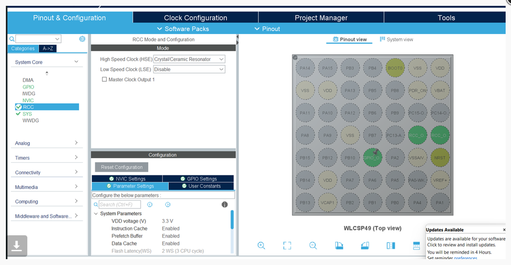
Add Configuration to STM32 Board
Configuring Your Board
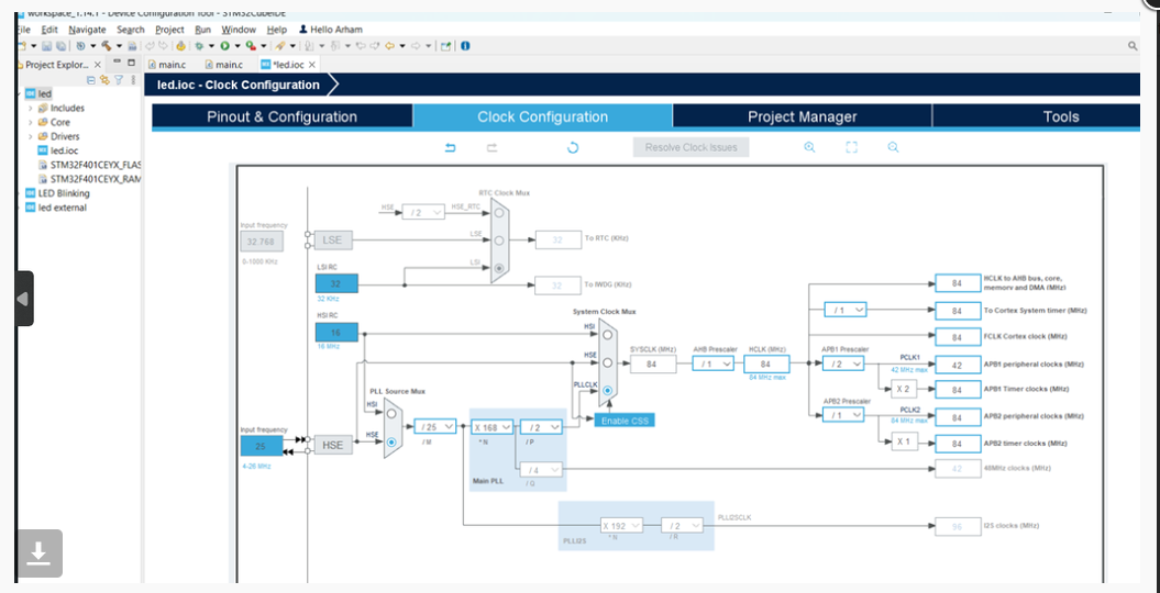
Configure Your Clock
Open Main.c File
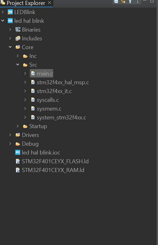
GOTO Project and find main.c file
Goto While(1) in Main() and Add Your Code
HAL_GPIO_WritePin(GPIOC,GPIO_PIN_13,0);
HAL_GPIO_WritePin(GPIOC,GPIO_PIN_14,0);
HAL_GPIO_WritePin(GPIOC,GPIO_PIN_15,0);
HAL_Delay(400);
HAL_GPIO_WritePin(GPIOC,GPIO_PIN_13,0);
HAL_GPIO_WritePin(GPIOC,GPIO_PIN_14,0);
HAL_GPIO_WritePin(GPIOC,GPIO_PIN_15,1);
HAL_Delay(400);
HAL_GPIO_WritePin(GPIOC,GPIO_PIN_13,0);
HAL_GPIO_WritePin(GPIOC,GPIO_PIN_14,1);
HAL_GPIO_WritePin(GPIOC,GPIO_PIN_15,0);
HAL_Delay(400);
HAL_GPIO_WritePin(GPIOC,GPIO_PIN_13,0);
HAL_GPIO_WritePin(GPIOC,GPIO_PIN_14,1);
HAL_GPIO_WritePin(GPIOC,GPIO_PIN_15,1);
HAL_Delay(400);
HAL_GPIO_WritePin(GPIOC,GPIO_PIN_13,1);
HAL_GPIO_WritePin(GPIOC,GPIO_PIN_14,0);
HAL_GPIO_WritePin(GPIOC,GPIO_PIN_15,0);
HAL_Delay(400);
HAL_GPIO_WritePin(GPIOC,GPIO_PIN_13,1);
HAL_GPIO_WritePin(GPIOC,GPIO_PIN_14,0);
HAL_GPIO_WritePin(GPIOC,GPIO_PIN_15,1);
HAL_Delay(400);
HAL_GPIO_WritePin(GPIOC,GPIO_PIN_13,1);
HAL_GPIO_WritePin(GPIOC,GPIO_PIN_14,1);
HAL_GPIO_WritePin(GPIOC,GPIO_PIN_15,0);
HAL_Delay(400);
HAL_GPIO_WritePin(GPIOC,GPIO_PIN_13,1);
HAL_GPIO_WritePin(GPIOC,GPIO_PIN_14,1);
HAL_GPIO_WritePin(GPIOC,GPIO_PIN_15,1);
HAL_Delay(400);
Debug
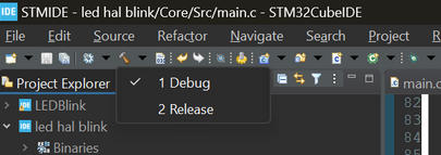
Open and Click On Debug(1)
Copy Path of .elf File Generated
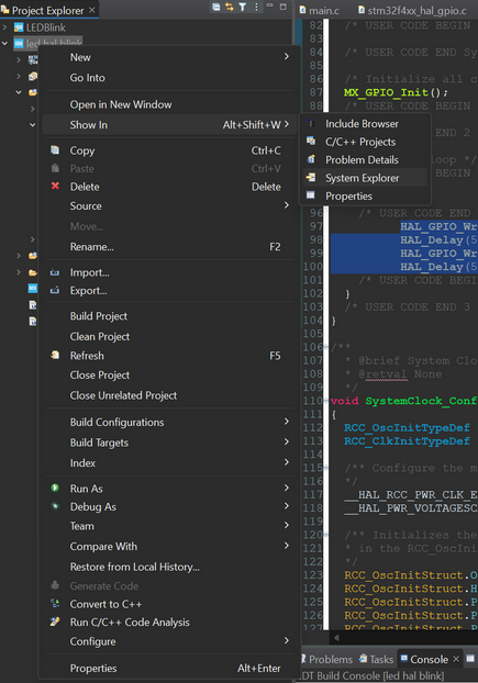
Right click on Project and click on show in system explorer and copy the path
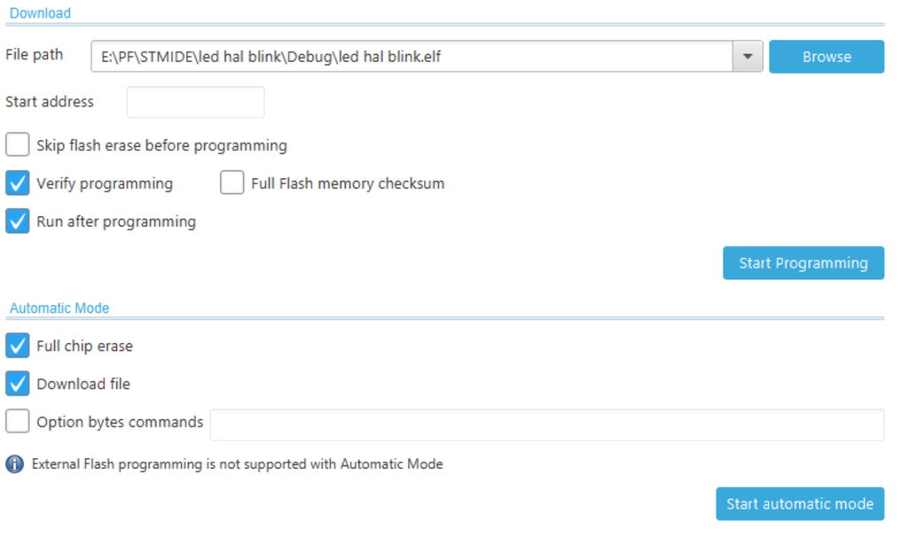
Open STMCubeProgrammer and Connect to STM Board Via USB
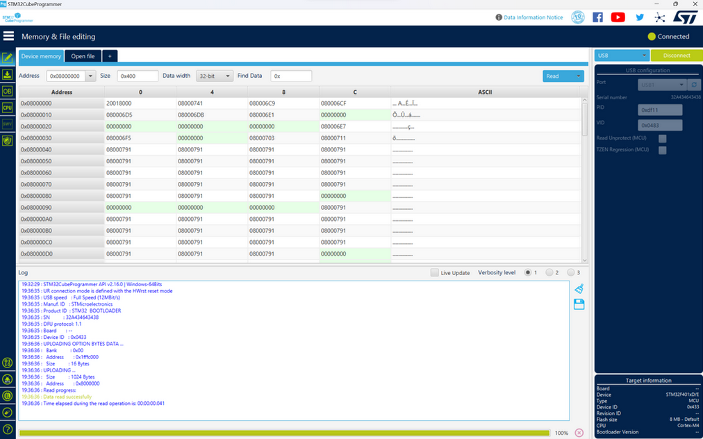
Go to Download Options

Change Download Options and Click on "Start Automatic Mode"