Blastgate and Dustcollection Automation
by steffstereo in Circuits > Electronics
384 Views, 1 Favorites, 0 Comments
Blastgate and Dustcollection Automation


This is a Project for automating Blastgates and a dustcollector in a Wood-Working-Shop
Supplies
Electronic parts:
1x Raspberry Pi4
1x Powersupply 5V for Raspberry Pi (in my case - Meanwell RS25-5V, 5A)
1x Powersupply 6V for Servomotors (in my case - PoppStar Universal AC Adapter / 6-16V / 5-3.5A / YSV60-1)
1x Breakoutboard (not necessary, nice to have - GeeekPi Screw Terminal Block Breakout Board)
1x PCA9685 Servodriver
2x Current-Sensor (Iduino TC-9520256)
1x Analog/Digital converter (Adafruit ADS1115 16Bit I2C ADC)
3x Servo (Reely Standard-Servo S3003 MG Analog-Servo)
3x Blastgate (4” Aluminum Blastgate - it`s noname)
1x Relay-Module 1-pin (5V/220V 1 Channel Optocouplers Relay Shield)
1x Relay-Module 4-pin (ABB ESB25-40N)
1x lot of Different cables (lo list cause it`s so individual)
1x Dupont connectors and pins set
Cabinet (individual)
Cabinet (wood/diy)
2m Din-Rails (Type IEC/EN 60715)
2m wiring channel / cable duct (Verdrahtungskanal)
12x PTS 1,5/S-TWIN (Durchgangsklemme)
Dashboard with Touchmonitor:
Touchmonitor (Portable Monitor Touchscreen 15.6'' FHD 1080P)
Wallmount for Touchmonitor (wood/diy)
HDMI-Cable 10m
Adapter Micro-HDMI(male) to HDMI(female)
USB-B to USB-C Calbe 10m
Power-supply USB-C
Hardware that can be helpful for testing the electronic parts:
- Multimeter
- Voltage-tester (e.g. duspol)
- laboratory power supply
- Servotester (e.g. Voktta RC Servo Tester 3CH)
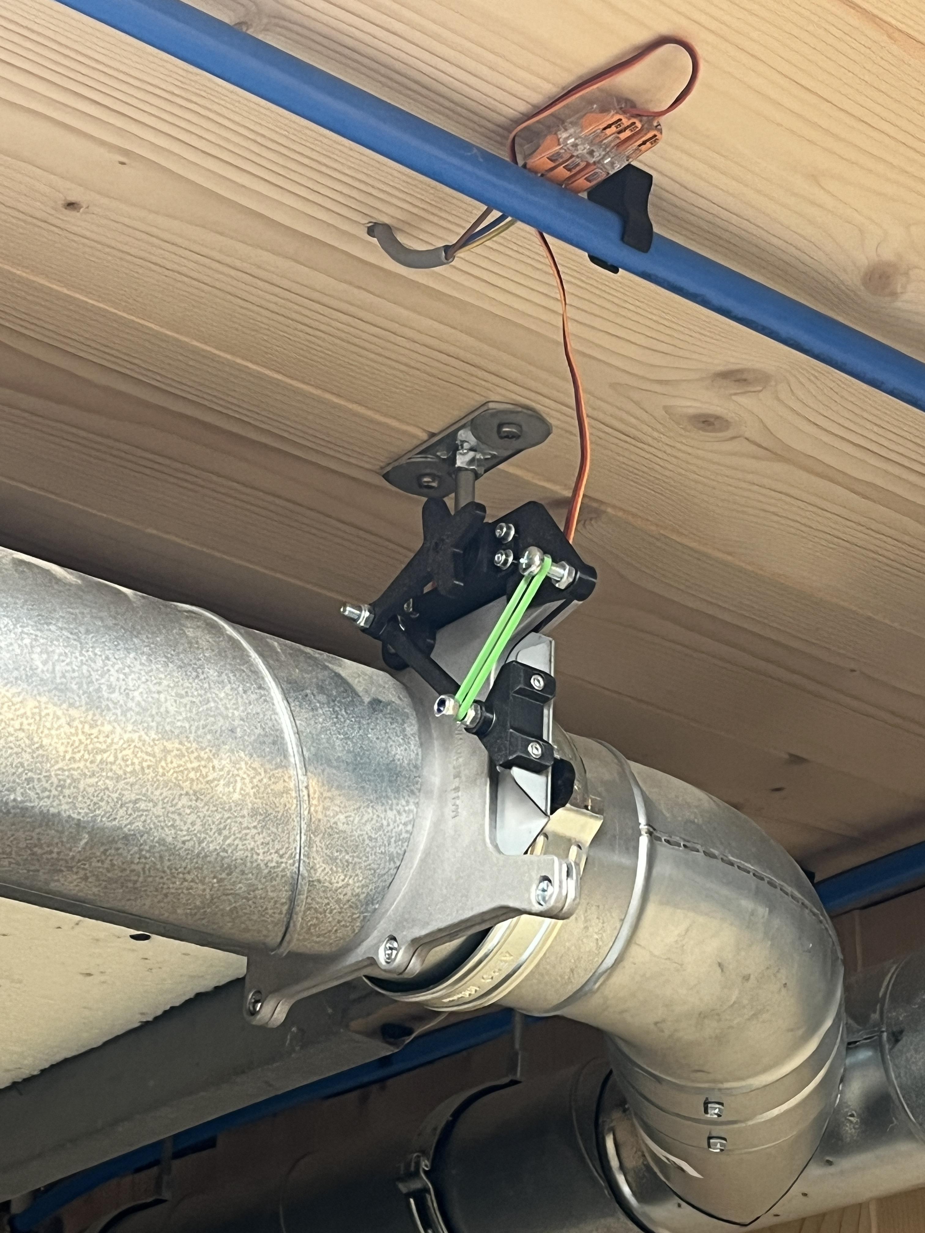
Blastgate Assembly


I`ve found a Blastgate Project thats was perfect for my requiremtns. It fits to a pipe of 100mm and is powered by a servo motor. I could imagine converting the blast gates to compressed air at some point, but I wanted to keep it as simple as possible and I used the servo perfectly for that.
https://www.thingiverse.com/thing:2573041
First I printed all the 3D parts and then mounted them to the blastgate.
After that was done, I connected the servo to a tester and carried out an initial functional test. You have to be very careful not to reverse the polarity of the servo, as this will lead to a defect.
Downloads
Testing Electronic Components


Then i connected the various components on a breadboard and carried out initial tests. After making sure everything worked, so many wires, it was a mess!
3D Print Parts - Mounting the Components in a Cabinet


I`ve printed out all the parts that I needed to manage the individual components in the control cabinet. I used a DIN rail to attach it to give it a kind of flexibility. Of course, this could be implemented much more easily, but if more machines are added in the future it will be much easier.
I uploaded the STL files for printing on thingiverse: www.thingiverse.com/thing:6817695
Put Together the Cabinet & Electronic Components)


In my case i used a selfmade cabinet out of wood, of course you can also use a standard electronic cabinet that is made out of plastic.
Wiring the Electronic Components


Then I connected all the cables as you can see on the circuit diagram.
I don't have an exact list which wires you need but there were some with 0.25mm² / 0.50mm² / 0.75mm² for electronics and servos and a few 1.5mm² / 2.5mm² / 4mm² for power distribution (saw, planer and dust-collector) but that depends on the machines.
I created the circuit diagram with the "Fritzing" program, here the file is in .fzz format
->Please be careful, working with electricity can be life-threatening! If you have no experience with electrical systems, please have it done by a professional!!!
Downloads
First Test
After everything was connected I did a functional test. After I had set up the first functions in nodered I was able to test the current sensor and the blastgates, as well as the relay.
Downloads
Installing the Cabinet at My Workshop


I installed the control cabinet right next to my power distribution in which the circuit-breaker for the saw, planer and dust-collector are installed. I ran one phase from the saw and planner circuit-braker through the current sensors and back again.
In my case, all machines (saw, planer, dust-collector) are connected with 3 pins (heavy current with 400V) because they are large and professional machines. If you wanted to connect smaller 1-pole machines, the whole thing would be even easier. If so, you would use a 1-pole relay instead of the 4-pole one.
-> Please be careful, working with electricity can be life-threatening! If you have no experience with electrical systems, please have it done by a professional!!!
Getting Started With the Raspberry Pi
Of course, you'll find plenty of instructions on how to install a Raspberry Pi and get Node Red running on it. That's why I won't discuss the individual steps any further here.
As a overview:
- Installing Raspbian on SD-Card with Raspbian-installer
- Integrating the Raspberry into network and making the first adjustments (password, IP-address, etc.)
- Installing node-red, probably easiest way via ssh access
This are the plugins/addons which i use in node red:
- node-red-contrib-anolog-to-digital-converter-raspberry-pi (libary for communicating with A/D converter)
- node-red-contrib-pca9685 (controlling the servos)
- node-red-dashboard (making a dashboard fpr manual control)
- node-red-node-pi-gpio (controlling gpios from the raspberrypi)
- node-red-contrib-calc
Creating the Node-Red Flow


Unfortunately, I'm not a professional when it comes to node-red. So I had to get help, i first worked on the flow with a friend of mine, but we didn't have a real concept and then we hit a dead end. Then we created a flow-chart and talked through the concept until we were reasonably sure that it could work that way.
I then commissioned a freelancer to create the flow in node-red, which went relatively quickly, but debugging was time-consuming and cost me a lot of nerves. Luckily the freelancer helped me with that, the flow now works as it should!
Of course the flow is also available on github: www.github.com/steffstereo/blastgate-automation.
Downloads
Installing Blastgates

After the flow got to the point where manual control worked, I installed the blastgates. I used a Lapp cable with 0.5mm² to connect the PCA controller (cabinet) to the blast gates. Unfortunately, I couldn't find a cable where the colors matched, so I had to be careful not to reverse the polarity of the servos motors. I made a sketch especially for this.
Touchdisplay for Manual Control


.jpeg)
In order to control the system manually, I decided to connect a touch display to the Raspberry Pi. I then access the dashboard via the Chrome browser. As an extension, I installed a screensaver so that the screen switches off after a certain time. It was a bit annoying to have the HDMI and USB connection over 10 meters from the Raspberry Pi to the screen. Of course you could also use a tablet to access the website, but I found it better to have direct access to the Raspberry OS. I would also like to take the pi off the network for security reasons.