Big Red Button That Runs Around!
by sophiazhu16 in Workshop > 3D Printing
1064 Views, 10 Favorites, 0 Comments
Big Red Button That Runs Around!


We made a big red runaway button. Press on the button, and it will jumpscare victims by suddenly dashing away. The project consists of 3 main steps: laser cutting, 3D printing, and circuit assembly.
Special thanks to Ms. Berbawy, our Principles of Engineering teacher, for giving us the opportunity to create our own engineering project, and helping us along the way.
This project was made by Elaine Lu and Sophia Zhu.
Supplies
Materials
- Wood (1/8 inch birch plywood for laser cutting)
- Clear Acrylic for laser cutting
- Arduino Nano
- 2 L298N motor drivers
- 4 omnidirectional wheels (2 right and 2 left)
- 4 TT motors
- Ultrasonic Sensor
- Jumper Wires
- Small Breadboard
- Compression Springs (similar product)
- 9v Battery Pack (similar product)
- M 3x10 Screws
- M3 Lock Nuts
- Twist Ties
- Heat Shrink Tubing
Tools
- 3D printer (we used Prusa Mk3s and Minis)
- Laser Cutter
- Screwdriver
- 9v Battery Pack Charger
CAD


You can download the CAD file here:
[insert CAD file]
Laser-cut the Wooden Box
From the CAD file, we generated Adobe Illustrator designs for all 6 sides of the box. You can simply download them below.
We used ⅛” birch plywood and a laser cutter to cut out the pieces of wood. (We also laser cut the exact same files of the wooden box in clear acrylic as well for display purposes, but you should use the wood box to hide the internal components if you truly want to prank your friends!) Don’t assemble it yet because we still need to make some 3D-printed parts, but here’s what it will eventually look like:

3D Printing
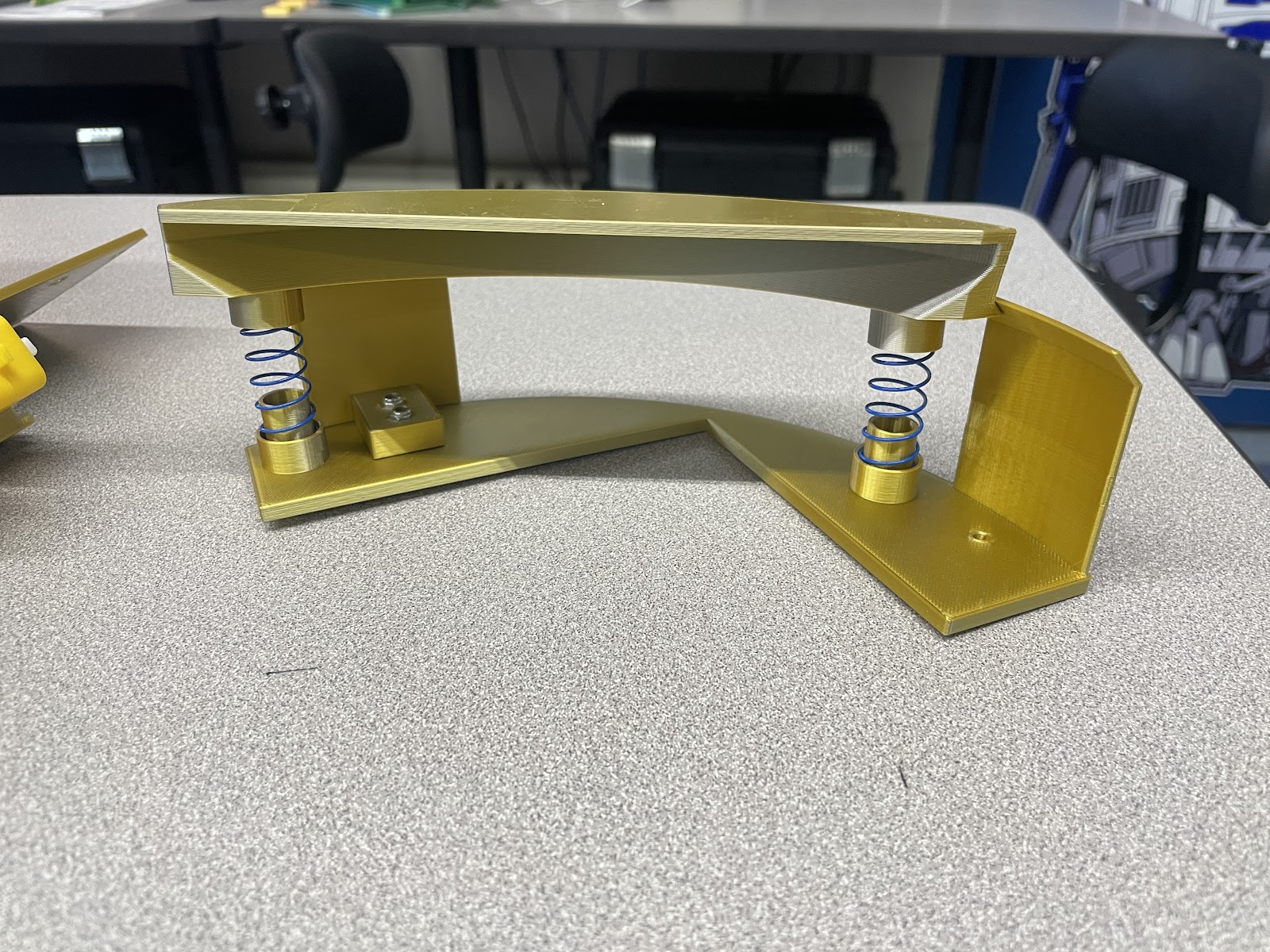
Next, we designed the button mechanism. The button cap will be supported by springs, like here. (These pieces are just a test print of the system.) However, because the pieces in the CAD file are too large to fit on the Mk3s, we had to split the top button cap in half and the bottom frame into four pieces. The top button cap has slots for screws and lock nuts to connect the two halves. The four pieces of the frame do not need to be connected to each other because they are to be secured to the wooden panel on the bottom.

We need a separate wall piece from the main frame because it will make it possible to put the arcade button cap in, otherwise the frame will be closed from all sides. It has slots for two Mx3 lock nuts to make sure that the screws will not slide out and hold the piece in place.

Then, we made a 3D test print of the slot for the ultrasonic sensor.
You can download the CAD files here:
Downloads
Solder the Motor Wires
.png)
- Get 8 long pieces of stranded-core wire with solid-core on the ends (the type that you use when breadboarding). A longer length and stranded-core make the wire more flexible. This reduces the force on the solder joint so that it doesn’t break.
- Loop the end of each wire around one of the metal loops of the motors. Cut a small piece of heat-shrink tubing and put it around the wire. Solder the wire to the metal loop. Here’s a tutorial for soldering.
- Use a zip tie to secure the wires around the motor.
Assemble the Wheels
It’s important to do the assembly in order, or you may find that the parts can’t be fitted together.
When making the robot car portion, we followed Smuger_WTH's Instructables on how to make a Simple RC Mecanum Wheels Robot.
- Gather these materials: 4 mecanum wheels, 4 TT motors, bottom wooden plate
- Arrange the motors and wheels. Ensure the wheels are facing outwards. There are two types of mecanum wheels, left and right. Make sure the diagonal tubes on the wheels form an X shape, like so:
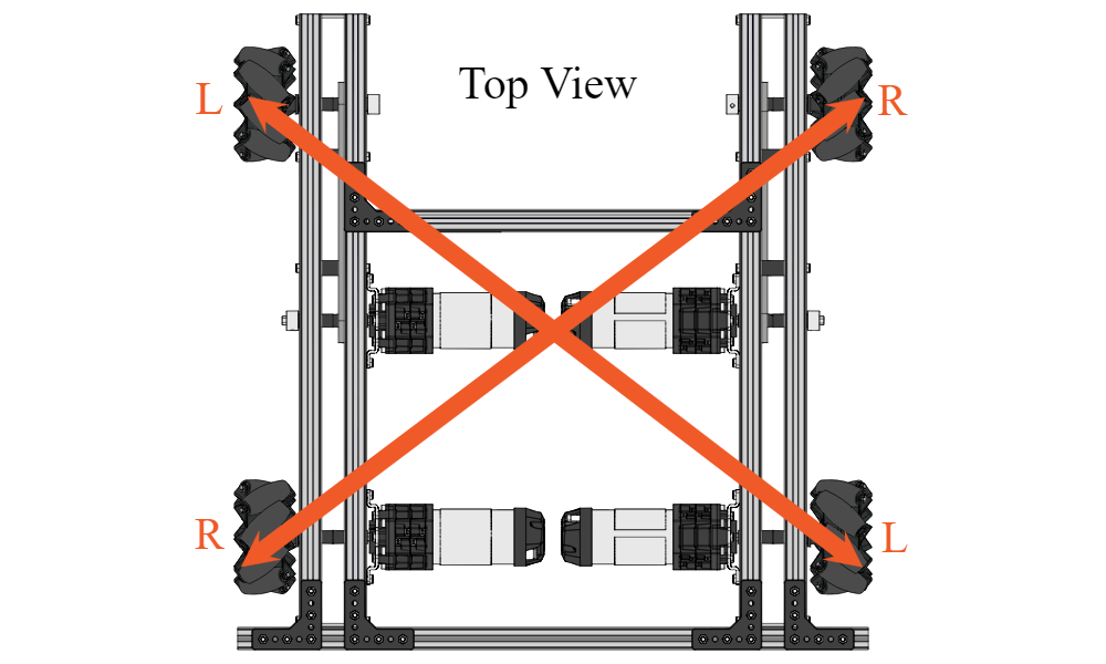
Image: Mecanum Wheel Setup and Behavior - DUO Build System
- Put the wheels into the motors.
- Use twist ties to secure the motors to the bottom wooden plate.
Connect the Bottom Plate
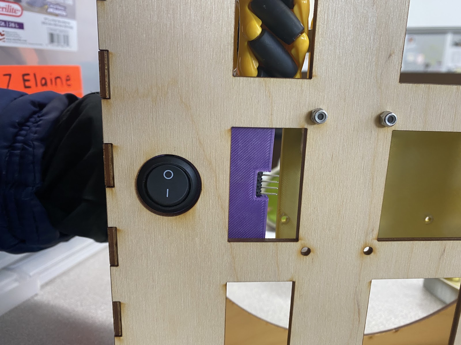
Using bolts to attach the bottom plate to the wooden panel, and then secure the bolts in place with lock nuts. Also, make sure the switch goes through the slot in the wooden panel.
Circuit Assembly


Warning: Never connect the positive and negative terminals of a battery without a resistance in the middle since that would create a dangerous short circuit. Always double-check your wiring before turning on the power.
First, connect the Arduino Nano to a small breadboard. Then, connect the L298 motor drivers to the Arduino, and two motors to each of the two motor drivers.
Then, wire an ultrasonic sensor to the Arduino. The ultrasonic sensor sits facing the lid of the button and recognizes when the button is just barely pressed. As soon as the sensor senses a distance threshold, it will activate the motors and cause the button to start racing away. You may need to calibrate it by adjusting the code.
Finally, connect a battery pack to the motor drivers. Connect a switch to the positive end of the battery pack, and the other end of the switch to one L298 motor driver’s 12v input slot. The negative end of the battery pack is connected to a common ground, to which the grounds of both motor drivers and the Arduino are all connected.
Coding
First, you will need to download the Arduino IDE, so you have somewhere to write the code.
Next, download the NewPing library for Arduino, which helps us code the ultrasonic sensor.
Then, you need to write code. Here’s ours, for reference, but some parts may differ depending on how you did the wiring and the dimensions of your button. The essential idea is that the ultrasonic sensor constantly watches the distance to the top of the button. When the distance is sufficiently decreased, it triggers the motors to turn and the button to run.
Downloads
Button Assembly

- Take the frame attached to the bottom wood panel.
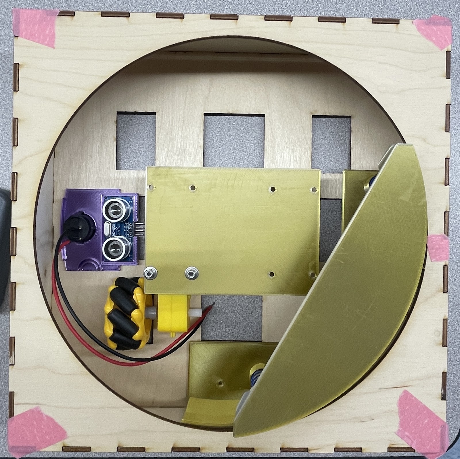
- Place the battery at the center of the plank, stack the breadboard on top, and make sure none of the wires are hitting the mecanum wheels.
- Connect the motors with the wheels attached in the correct orientation to the wooden panel using twist ties or 3D-printed brackets.
- Put the switch in the slot for the switch, which is the hole in the frame and the bottom wood panel.
- Place the button cap onto the springs with the tubes matching the spring locations, and make sure the edges of the button cap are under the tabs of the frame.
- Then connect the other wooden side planks to the bottom plank and glue the walls together.
And that’s it!
Prank Your Friends

.jpg)
Make sure you have enough space for your button to run around. Then, show your project to your friends and watch them get jumpscared. Enjoy!