Bicep Trainer

This Instructable is about making a Bicep Trainer using Arduino.
This machines ensure your posture of bicep training is correct, and helps you count how many reps you have done.
Supplies
1 Arduino Board (Arduino Leonardo used in my case) (Link)
1 Bread Board (Link)
1 Green LED light (Link)
2 Buttons (Link)
1 16x2 I2C LCD Pannel (16x2, I2C) (Link)
1 Buzzer (Link)
1 100 ohm resistor (Link)
2 110 ohm resistor (Link)
2 crocodile clip wire (Link)
4 Female to Female Jumper Wires (Link)
14 Male to Male Jumper Wires (Link)
1 box (Optional) (Any size bigger than the arduino and bread board combined, and able to open holes on the box)
Preparation


Prepare all the supplies on the list above.
Connect Arduino with your computer or external power supply. Connect the positive charge on the bread board to 5v on Arduino, and connect the negative charge on the bread board to GND on Arduino.
LED

Build up the circuit above on your bread board.
Connect the positive charge of the LED to D12, and negative charge to the 100 ohm resistor and negative charge on the bread board.
Note: Use crocodile clip wires to connect the LED to the bread board so the LED can be extended out of the box.
Buttons

Build up the circuits for the buttons as the image shown. The button connected to D4 is the one to determine whether a rep is done, and the button connected to D5 is to clear the record of reps done.
Note: Change the resistors into 110 ohm resistors.
Speaker

Build the circuit for the speaker as the image shown. Connect the positive charge of the speaker to D9 and negative charge to the negative charge on the bread board.
Note: The red line of the speaker is positive charge and the black one is negative charge.
Code
Upload the code below to the arduino.
Box


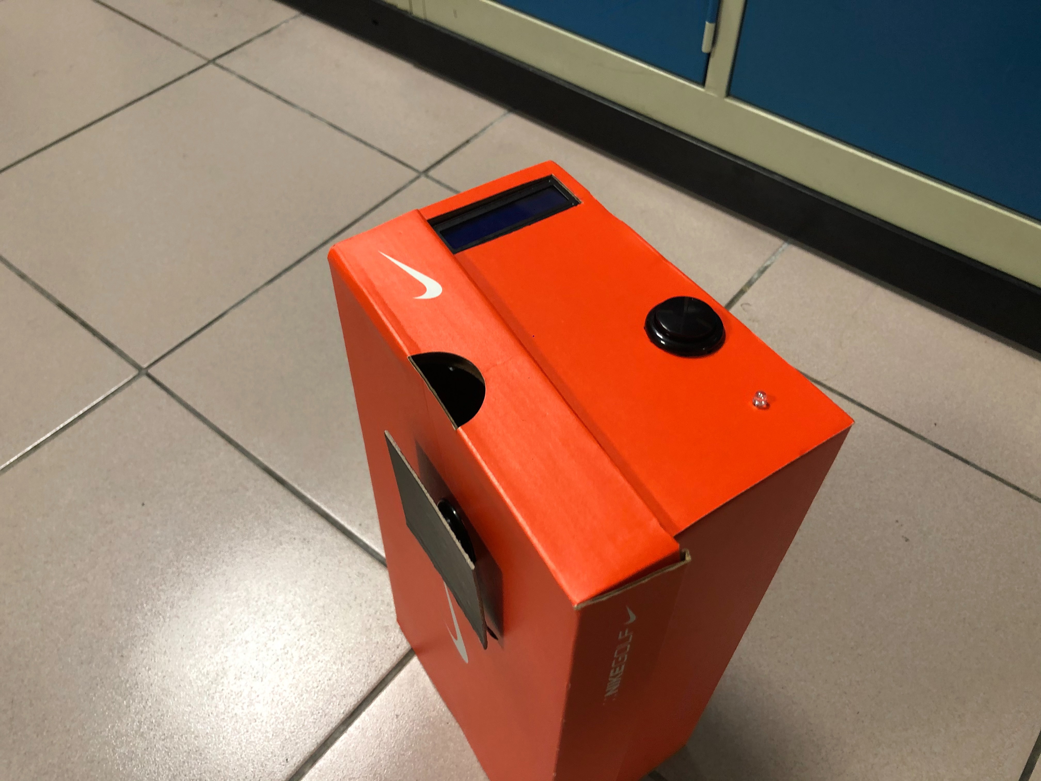
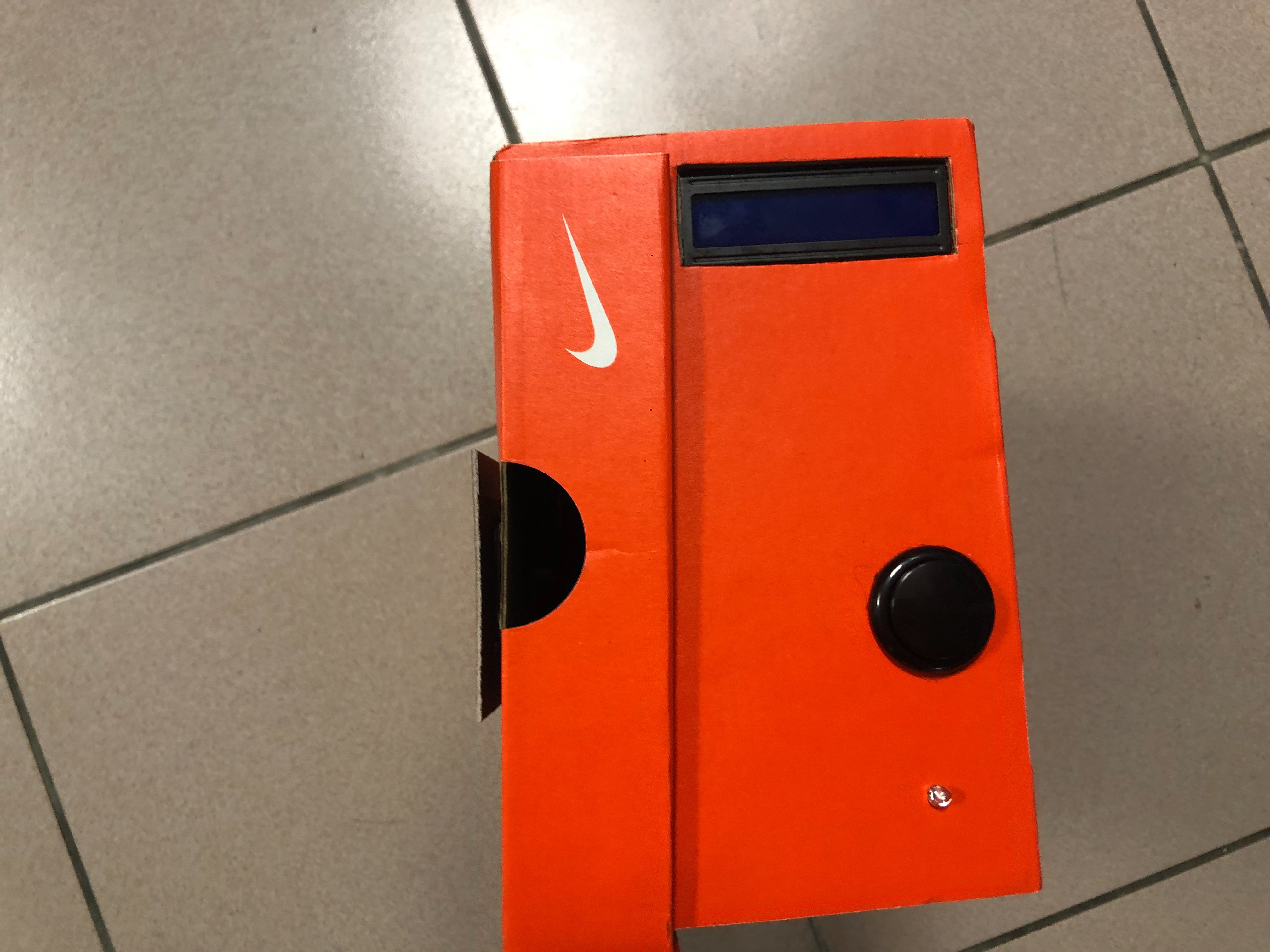
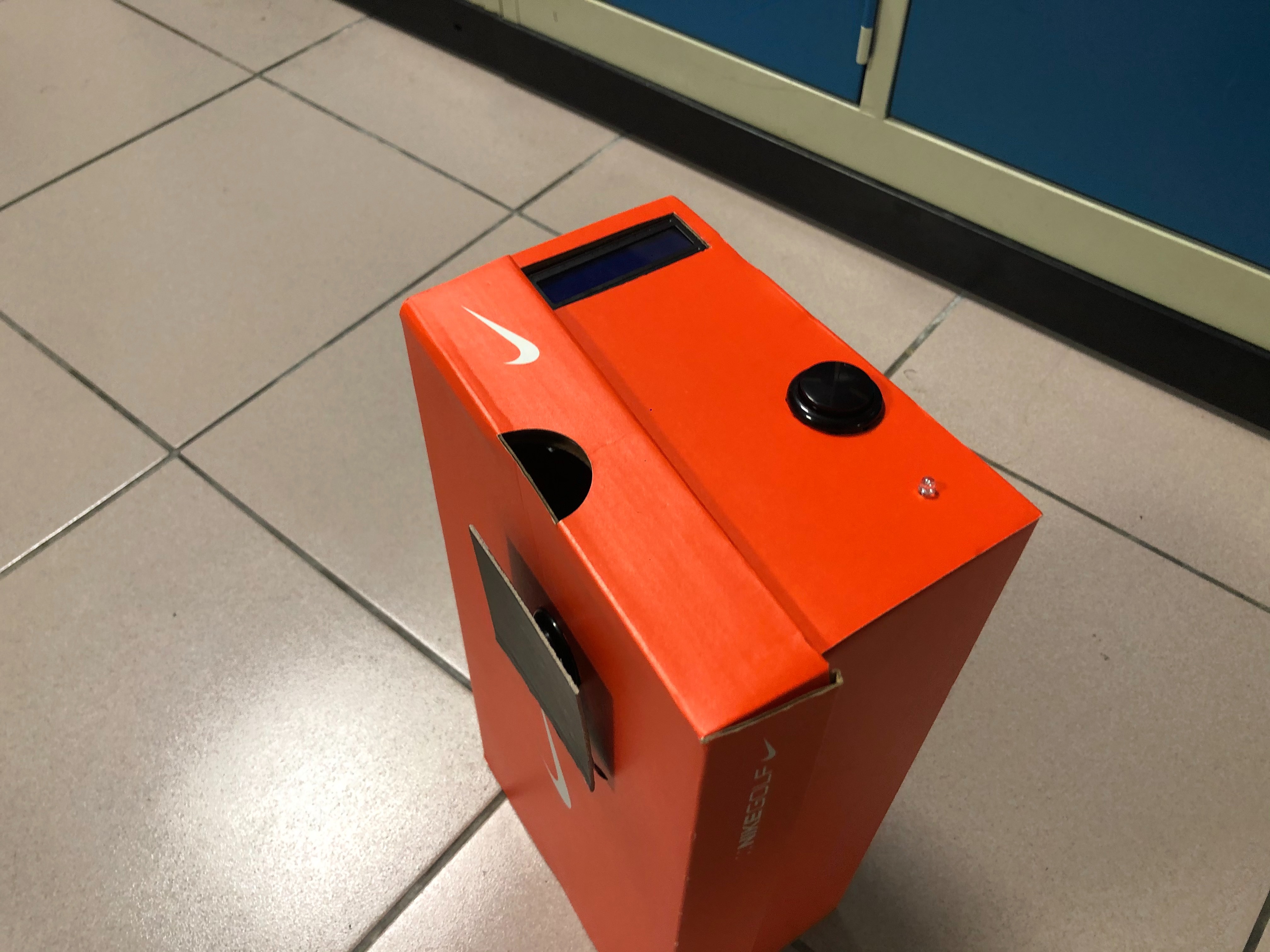
Measure the size of the buttons, LED and LCD panel. Open holes that fits the components on the box. As the images above shown, the LCD panel, LED, and the button to clear the record of reps done should be on on side of the box, and the button to detect whether a rep is done should be on another side.
Note: I added a black board on the button detecting whether a rep is done to increase the area of detecting to avoid the probability of missing the button after finishing a rep.
Testing
Now, test the device. If the device doesn't work properly, take a look at the wires and the circuits to make sure there are no mistakes.
Possible issues of the LCD panel and solutions:
Doesn't light up
Solution: The wires are misplaced
Lights up but only a white line without words
Solution: Change 27 in the code "lcd_I2C_ 27" to 3F
Words are not clear or covered by a white line
Solution: Adjust the screw on the back of the panel
Video: