Bezels for Microscope Slide Pendents Designed in Tinkercad and 3d Printed
by dimdiode in Craft > Jewelry
746 Views, 2 Favorites, 0 Comments
Bezels for Microscope Slide Pendents Designed in Tinkercad and 3d Printed
This project is to specifically cover the possibilities of using Tinkercad to design components, which, when 3d printed could be considered to be elements in jewellery making.
Usually I make jewellery from driftwood, sea-glass, recycled mechanical elements, such as watch parts, and other found / re-purposed materials. I have an Instructable on my ‘Cogbling’ ear studs, on this site.
However, I decided that as this contest had a specific prize aimed at the use of Tinkercad, I would share some of the items I have designed and made using Tinkercad and 3d printing.
Before I begin, I would like to share some thoughts, offer some caveats (weasel words)
1 What is jewellery? Since that sunny day man decided that living on the ground was more pleasurable than occupying the trees, man has adorned himself. Sometimes with the marks of dried mud, sometimes pigment jabbed beneath the skin by means of a porcupine quill, and sometimes with objects like sea shell, pretty stones, feathers - you get the picture. Jewellery - the adornment of oneself with decorative objects is an incredibly subjective issue. All sorts of materials have been used down the years - obviously in the earliest days these would all have been natural materials - often rare metals, rare stones (also called precious) and fascinating materials such as amber and lapis lazuli. Leather has been used along with less rare metals such as copper.
Obviously in more recent years we have access to man-made, as well as natural materials. Although precious metals and gems still form a major part of jewellery making, the world of jewellery these days is a much broader subject. Precious metal wire, ivory, pearls, coral - all kinds of exotic things have been made into jewellery over the millennia, is there any will to accept modern, man-made materials as jewellery? Can plastic (the most common material used in 3d printing) ever be thought of as attractive enough to be considered jewellery? We will be investigating that question in this Instructable.
2 Tinkercad is probably very well know to many folks on Instructables - and I do not purport to be an authority or expert in its use. I do what I do, and I will explain what I do. I imagine lots of folks would like to make observation that my approach is no good. Well, OK, but as I now fall into the category of ‘old dog’ I am glad to forgo any (well meaning) guidance or direction towards ‘new tricks.’ But thank you, anyway. Tinkercad is, in many ways, a splendid tool - especially as it’s free. It also has a few challenges - but there are often ways round to get where you want to be. I’m not grumbling, often times there are great pleasures to be found by achieving something in an environment with limitations. Tinkercad may well be considered a simple, unsophisticated tool, but it is in actuality, more than adequate for most users for the production of the 3d printed articles they wish to design. The designer simply has to get their head round how to get what they want out of it.
The basic function of Tinkercad is to allow the creation of (relatively) complex shapes by adding and subtracting simple 3d objects, called ‘primitives.’ Some people have made some remarkably complicated objects, from these simple building blocks. By the way, the notion of block code in Tinkercad is not covered in this little piece. I have had a look at it, and from first glance, i can’t see the point. Maybe I’ll ‘get it’ at some point, but just now I am leaving it alone. So, with Tinkercad, you can start with a simple thing like a cube or cylinder, for example, and within a couple of seconds you can produce more complex structures by ‘welding’ things together (Boolean union) or you can cut shapes away from objects by combining objects designated as holes, with objects designate as solids. Where the hole intersects with a solid, in three dimensions, the entire overlapping volume is removed.
Another really great thing about the software is that it is entirely non-destructive. You can go to a project which you created years ago, choose a complex object, and if you select ‘ungroup’ the very last ‘group’ operation you performed, is simply undone. In a sense it’s procedural - you can imagine the shape you regard as being described by a series of instructions. For example: place a cube, resize it, move it, rotate it. Add another cube, move it to intersect with the first cube, select ‘group.’ The resulting 3d shape is unique, but made up of simple primitive objects manipulated in a way described by the software. it’s really neat.
One of the things I like in Tinkercad is having the idea for a ‘product’ or item, and trying to work out the best way to build the object. Getting those steps, the procedures in the right order. If you can see in your mind’s eye your 3d goal, it then becomes a fascinating challenge to see how to build the thing. It’s a lot of fun. To me, it is, anyway.
3d Printed Bezels - General Form Designed in Tinkercad
Picture 1
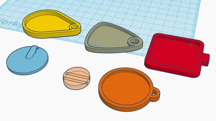
Here are a number of different bezels. They are mostly made the same way, with the overall shape being the main distinction between each of them. The 3d printed equivalent of a ‘bail’ or ‘jump ring,’ is the only other detail variation. Some have holes simply punched through the body of the bezel, other have a ‘ring’ of sorts added to the periphery of the bezel. One has a hanging hole hidden on the back of the bezel, and one has holes for a cord to go through the bezel. This last one would not have a deep inset, as the holes are located mid way down the thickness of the bezel. I will cover how I go about making these bezels, in the next section.
Initial Bezel Design Steps
Pictures 2 to 11
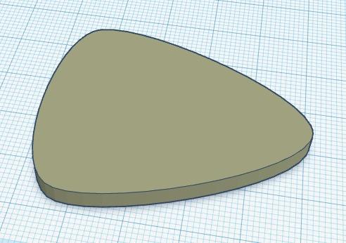
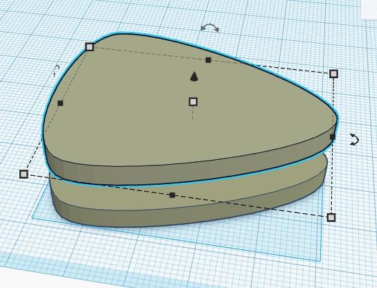
This sequence shows the very simple means of producing a three dimensional shape which will be exported as an stl file, for printing on the 3d printer. P2 shown the shape I have chosen - it’s the ‘circular trapezoid’ provided shape, in the Shape Generators section of the free elements within Tinkercad. I make a duplicate by holding down ‘shift + alt’ on my mac, and pulling the black arrow upwards - this duplicates the shape. It’s perfectly possible to ‘copy and paste (cmd c, cmd v)’ but the alt-shift method ensures the items stay aligned, which is useful.
After getting the duplicate, I make it 2-3 mm smaller in x and y, make it a hole, rather than a solid (P4) then drop it back into the original shape (P5). I make sure the hole is one or two mm above the base plate of the original object, then group them from the options in the top right corner of the Tinkercad screen. This has the effect of a Boolean operation, adding a hole to a solid, makes a cavity the shape of the hole (P6.)
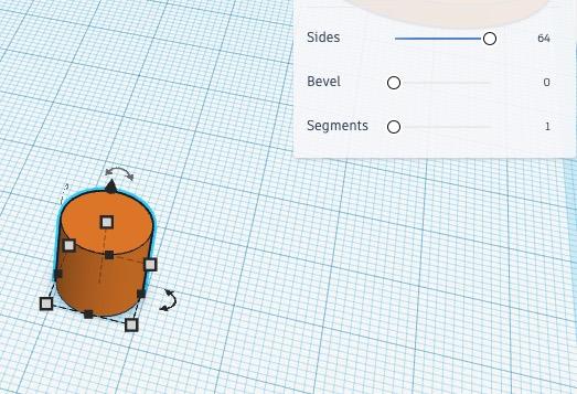
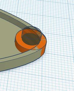
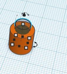
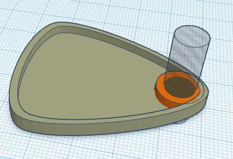
At this point, I decide to make a hole for the pendent cord, so choose the cylinder object from the tray of Basic Shapes, I make it the diameter I want (the height is entirely irrelevant at this point. Picture 7 shows that there are options to have the circle either relatively ‘low poly count’ or quite smooth. I want it to be as smooth as possible. Because I want a ring around the bezel hanging hole, I wish to cut a smaller hole out of the middle of this cylinder to make it into a ring. Yes, I could use the various rings and donuts offered in the shape generators - but I am stubborn, I have always used this method, and I guess I always will. So, Picture 8 shows the two objects. I now either make and group both of these elements as holes or as solids, it doesn’t matter which. As they are grouped, I can use the alignment tool to get the elements where I want them in the main object. Picture 9 shows them aligned centrally in the narrow axis of the bezel, and to the right edge of the bezel. Now I make the smaller cylinder into a hole. Picture 10 shows this arrangement.
It’s one of the features of any Boolean operation that you make sure the order of processes takes place properly, in order to get the result you want.
If I cut the hole out of the ring, then weld the ring to the bezel, there won’t be a hole in the bezel. So I must perform the operations in the right order. I make the larger cylinder the same height as the bezel, then I weld the ring to the bezel, by making sure I select just those two items, and clicking the ‘group’ button. I can then select the newly combined bezel+ring, along with the small cylinder hole, and perform the Boolean union, thus ‘drilling’ a hole into the bezel, through the centre of the ring.
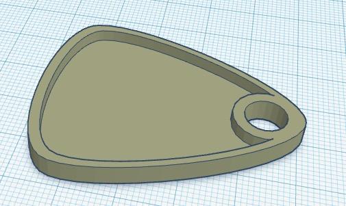
All extremely simple, but important to get right to achieve the effect you seek.
Pictures Remaining From Step 2, Above
Different Types of Bail, or Jump Ring
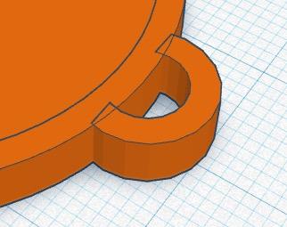
Picture 12 is simply there to show how I make a ‘bail’ rather than a hanging hole. I have simply made a ring by the same method as above, cut a chunk off and then I will weld the new shape onto the rim of the bezel. Again - there are shapes which I could use, but honestly, I am happy in my ways.
Pictures 13 to 16
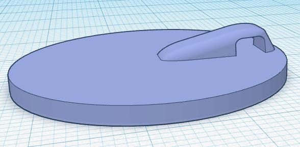
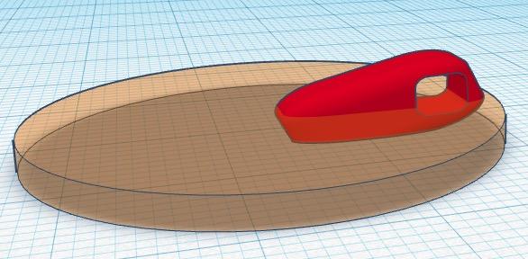
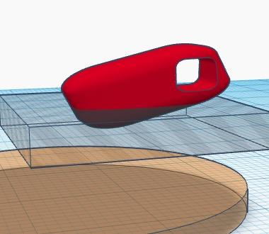
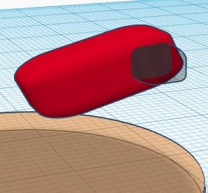
This is a simple sequence to show how I have created this little shape to be a hanging hole hidden behind the bezel. The odd little red shape is a cylinder, with rounded bevel, stretched into an elongated rectangular volume. Here is one of the limitations of Tinkercad. it’s not a problem in this object, but it would be useful of the bevels didn’t ‘scale’ with manipulation of volumes. By pulling the beveled cube in one axis, the bevels become badly distorted, which is inconvenient. As I say, it’s not really a hassle here, but later I will show an example where it’s a bigger issue. So, in this example, I put a little oblong hole, into a larger oblong solid which has already been rotated slightly. The union of the hole and solid is then trimmed so it doesn’t come through the front of the bezel, then this unified shape is ‘welded’ to the bezel with the Boolean union (group) operation.
A Pendent / Plaque Designed by Importing SVG Files Into Tinkercad
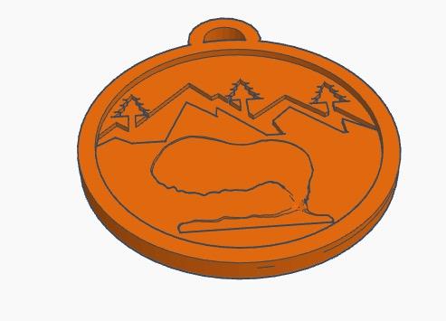
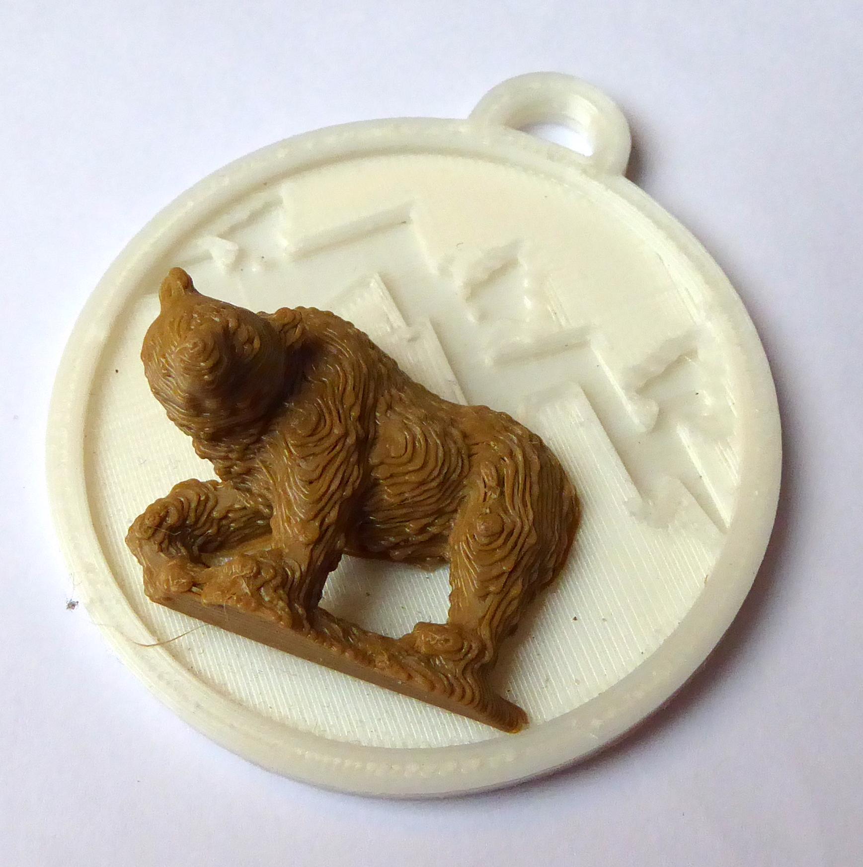
Pictures 17 to 21
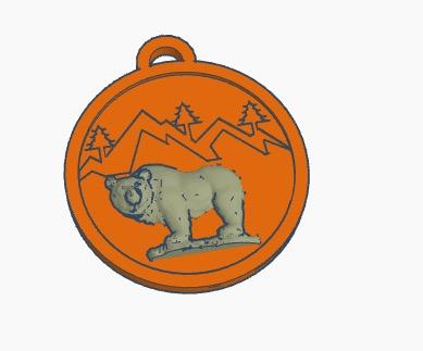
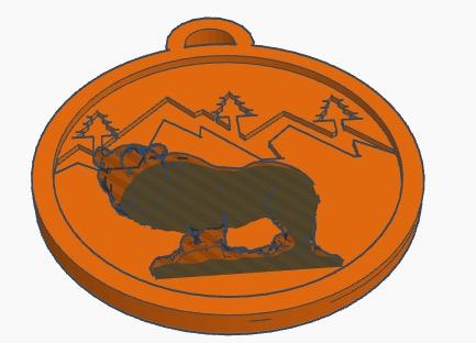
Here is an example of a pendent I make, which is printed in 2 parts. It is a 3d bear, on a stylised mountains / trees background. It’s possible to do this with a brown bear or a polar bear, with bezel colour of any colour. The mountains / trees was drawn in an illustration package, and imported as an svg. This feature in Tinkercad is really great. if you can draw an image, it can come in and be used in your 3d printable designs. There are limits to size physical dimensions, so beware, some illustration packages do not make it easy, and produce svg files of an unexpected vastness.
The svg is simply imported, if you have your geometry correct it will be a filled, solid shape, so making this shape into a hole and cutting out the design is simply the same Boolean exclusion operation described before.
The bear is not my work. I got it from Thingiverse - it was made by Ronald45, and is here: https://www.thingiverse.com/thing:2843829
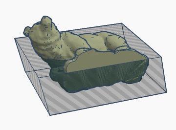
I have modified the bear to make it mount more flush with the bezel, Picture 18 shows how I have tilted the model then chopped off the lower part. Picture 19 shows how I make a duplicate of the bear into a hole, to cut out a very shallow bear-shape into the bezel, Picture 20.
I 3d print the two parts, the bezel and the bear, from different coloured plastic and then glue them with cyano. The little cutout shape provides a good location, and it also makes the glued part more secure.
Another Pendent From Imported SVG Artwork
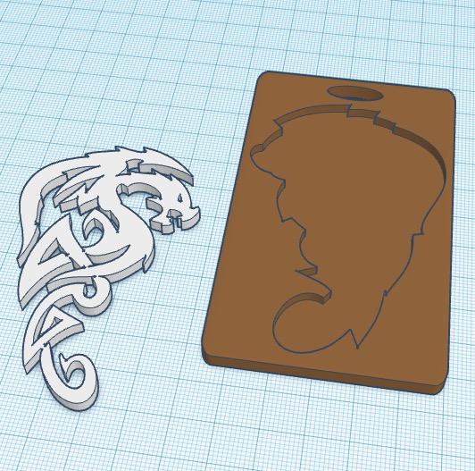
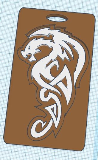
Picture 22 and 23 shows a little plaque / pendant, which I like to make. it’s quite similar to the bear, and like the bear pendent, this one is printed in 2 parts as well. Picture 22 shows how I print the dragon - I print it face down on the printer bed, because I get better results on the floors of my models than the roofs. The plaque has a ‘cutout’ of the dragon shape, which was produced in Adobe Illustrator. I took the dragon shape and produced an ‘inflated’ outline which was saved as an svg and imported into Tinkercad. The dragon was also an imported svg. I don’t know where I got the dragon - it may be one of the hundreds of thousands of vector clips I have, or it may have been an outline from a celtic typeface. I just can’t remember. Anyway, I print the dragon in a different colour and glue it into the ‘relief’ in the plaque, the end result in Picture 23.
Glass Slide Bezels
We now come to the ‘special’ bezels I have been making.
I discovered low temperature enamel (which isn’t enamel in any true sense of the word. Enamel is ground glass and need a very high temperature to melt, low temperature enamel is a fine powdered polymer-type material, which melts at only 150ºC.) I found the stuff to be quite intriguing - and along with embossing powder, decided I needed to be experimenting with them.
I did a number of metal (purchased) bezels, with embedded objects etc, and was pleased with the results. While considering where the experiments would take me next, I decided I would like to see how these ‘low melt’ powders would work on glass. The easiest way to experiment in this way was to acquire microscope glass slides, which are small, and inexpensive.
I did some experiments with slides, and they came out really well, in appearance, but I hit a snag immediately. I found the glass slides - although fairly robust, could under certain circumstances, break into pieces. This was a bad thing, if offering these as adornments for the body. Broken glass and flesh is not a happy combination. I also realised that microscope slides have sharp edges and corners. This is another bad thing.
So, here I was on the horns of a number of dilemmas. These materials require heat to melt them to make them attractive, so must either be used with metal bezels, or, if determined to use the glass slides I was going to have to find a decorative way to present them. I made a few slide holders from drift wood, and they seemed to work well, and obviously they were all unique.
However, I decided that I needed to ‘production line’ my glass slide pendent making, so concluded I needed make a design which could be made on my 3d printer.
I did a lot of design work, and I made a number of preliminary prototypes. Eventually I arrived at the design you see here.
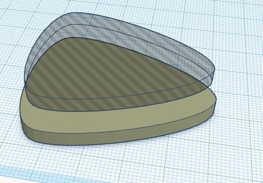
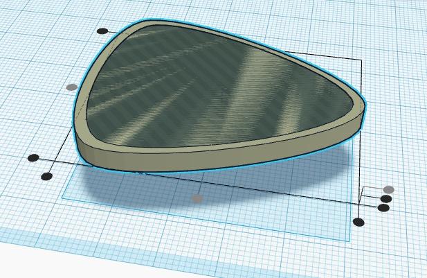
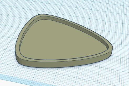
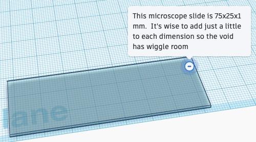
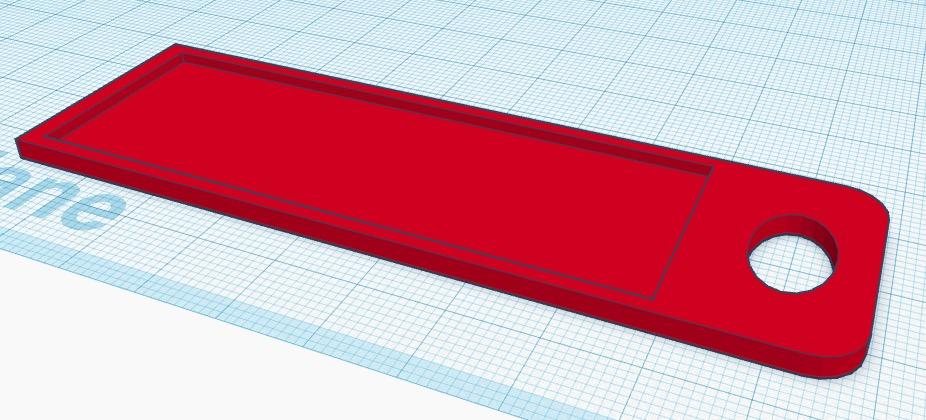
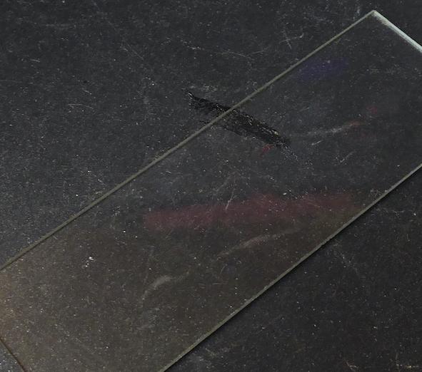
Pictures 24 to 34 show the whole process. P24 is the slide, though I make the ‘void’ shape just a smidgen bigger than the official dimensions, for ‘wiggle room.’ P25 is the finished bezel, and I will go through how I get to this final shape, here.
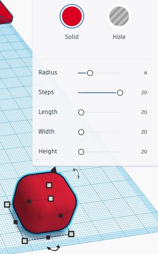
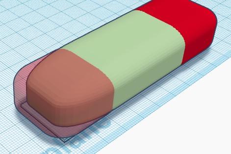
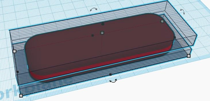
Picture 26 shows the starting point, which is a beveled cube. The controls for the bevel parameters are shown. As mentioned before, Tinkercad has the unfortunate ‘feature,' that bevels scale, rather than maintaining their dimensions. So, Picture 27 shows the rigamarole I have to go through to get the final shape I want, which is a flat oblong with rounded corners. The best way i have found (I am sure there are others :) ) is to make three beveled objects, two cubes and one stretched cube. By joining them together as in Picture 27, I can end up with a stretched 3d rectangular volume with consistent bevels. In P28 I show how I then add a hole on top and a hole on the bottom, which are both Boolean joined to the oddball stretched beveled rectangle, to produce a rounded corner flat object as in P29.
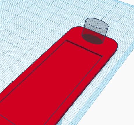
I use the initial ‘slide’ object to cut a void with right angle corners into the rounded rectangle then I cut a nice oval cord hole in the end.
Glass Slide Bezels and Materials

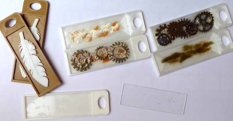
Picture 30 show some of the pendants I have made over the years. Most have microscope glasses, but the ones with the feathers are simply empty bezels with added objects. If I don't need heat to melt materials, I don't need the glass.
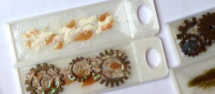
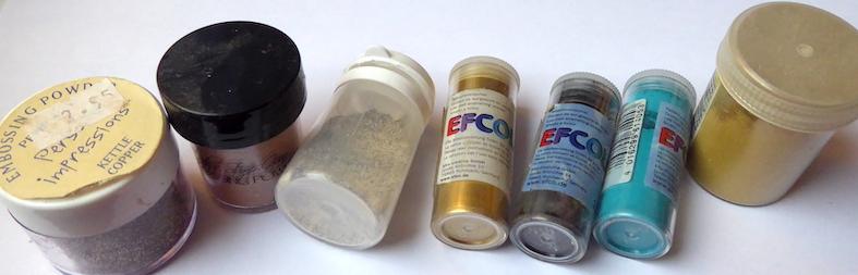
The method or decoration, which started this entire escapade, was to be brought about by using low temperature enamel. Of course, this is a product name, it’s not ground glass, the way real enamel is, because if it was it couldn’t fuse at low temperature, which is the entire USP of low temp enamel. I really like the stuff, as well as the embossing powders. both are available in lovely colours, and although very different, they tend to work well, together. Picture 31 shows a VERY few of the very many low temp colours I possess.
These low temperature embellishing powders can be melted and fused to objects with a heat gun. Unfortunately heat guns tend to work by way of a blast of hot air at high velocity. This, of course would result in the obliteration of the desired design.
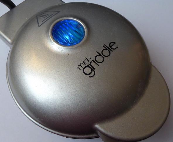
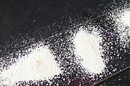
So, I decided I wanted a handy little way to heat up small objects for the application of these colours. i didn’t want to use a toaster oven, because although they are small, and are flexible as they also can function for hardening poly clays, i wanted something smaller and neater. A single burger cooker seemed to be the ideal solution, and it’s worked out really well. P 32 shows the one I bought - I am sure there are many. P33 shows the glass in there heating up, and P34 shows some embossing powder just reaching melting point.
Sure, there’s usually some ‘over spill,’ brought about by being sloppy, and also by not being as limber as I once used to be. it’s not a big deal, the melted goo on the hotplate simply wipes off with kitchen paper, prior to doing subsequent ‘melts.’ This picture shows the material melting - it gets a lot less 'globular' as it gets hotter.
Conclusions Is this jewellery? well, in the context that the Instructable Jewellery contest specifically invites Tinkercad entries, then I hope you’ll agree that this entry meets the specification. I have showed how I use (emphasis on ‘I’ ) Tinkercad to make certain ‘jewellery’ components, such as bezels. I have also showed how I make decorative plaques which I offer as pendents, but could be refined and purposed as tree ornaments etc. Finally, I show how I use my 3d printed, and a Tinkercad designed bezel to offer rather individual pendents using microscope glass slides. I hope you’ve found my little journey to be of interest.