Beheaded Doll Night Light
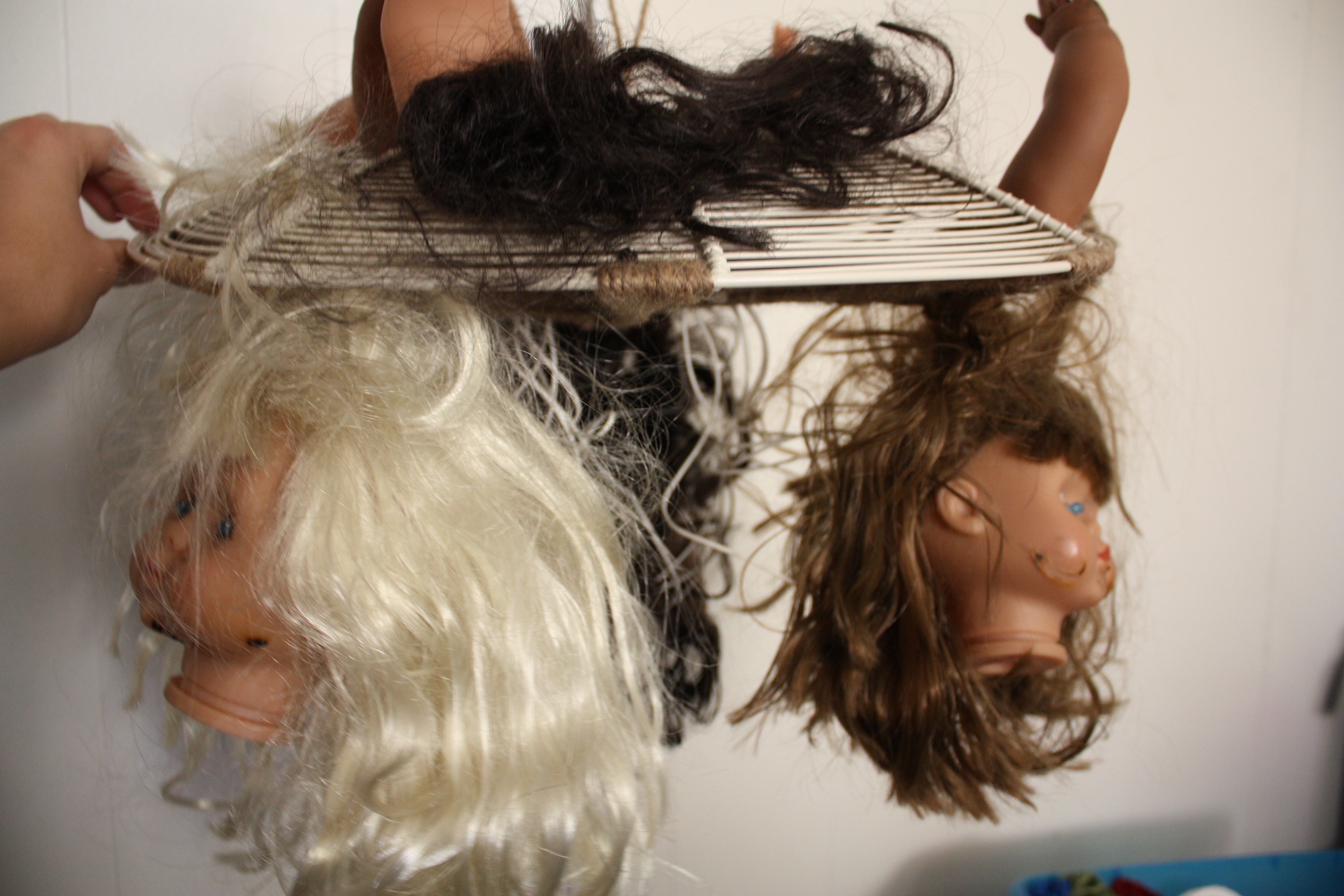
This is a Beheaded Doll Night Light. It automatically turns on when it gets dark!
I am going to walk through how to create a Beheaded Doll Night Light such as the one I made. This was inspired by Bot1398's Instructable "Light Sensing LEDs" and is primarily the foundation for this Instructable with my own added twist.
I am going to walk through how to create a Beheaded Doll Night Light such as the one I made. This was inspired by Bot1398's Instructable "Light Sensing LEDs" and is primarily the foundation for this Instructable with my own added twist.
Step 1: Parts, Tools, Supplies - Oh My!
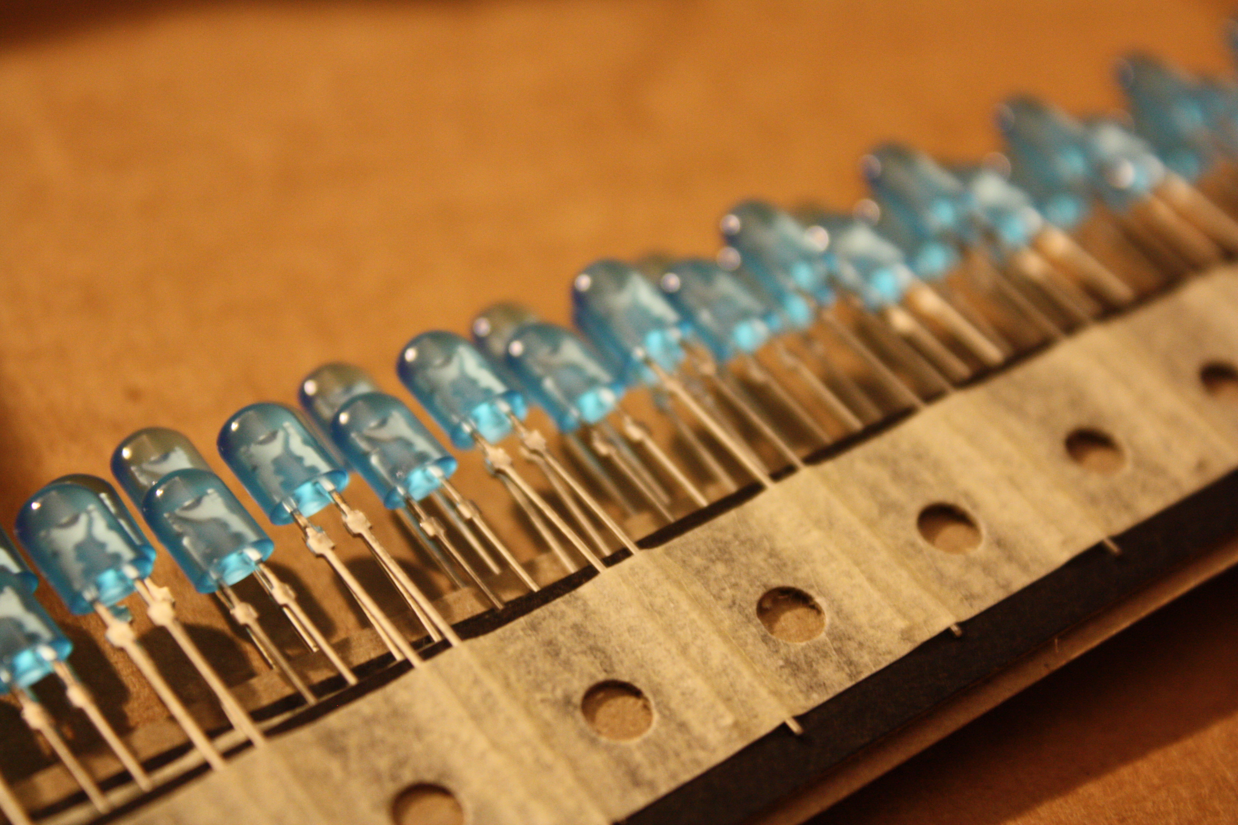
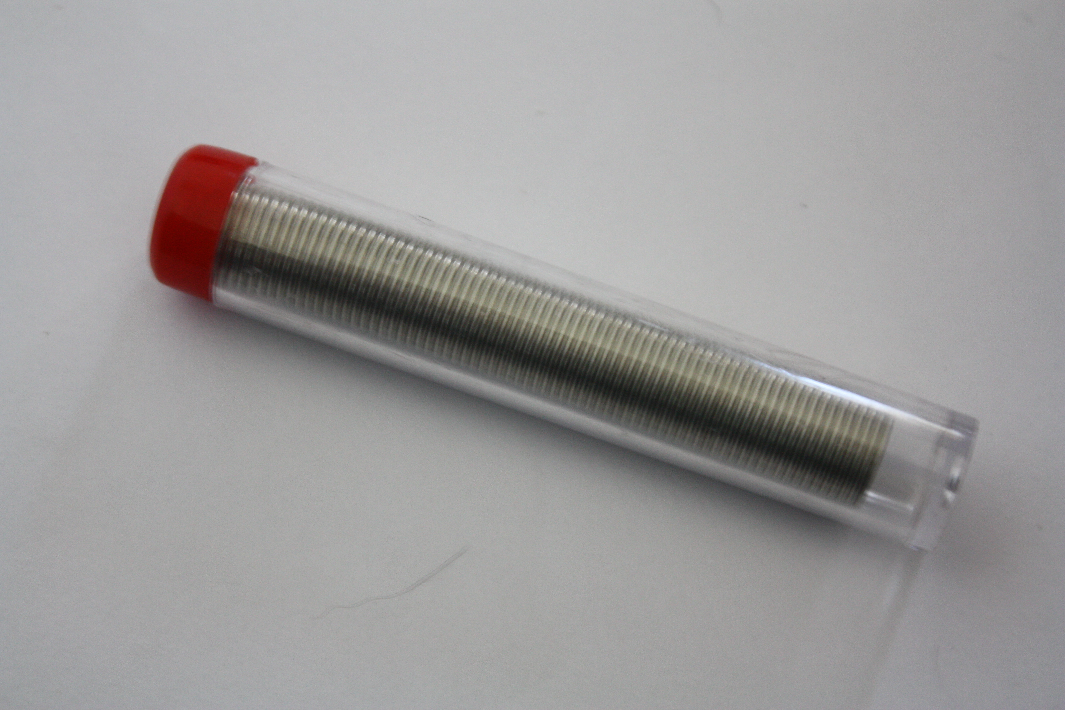
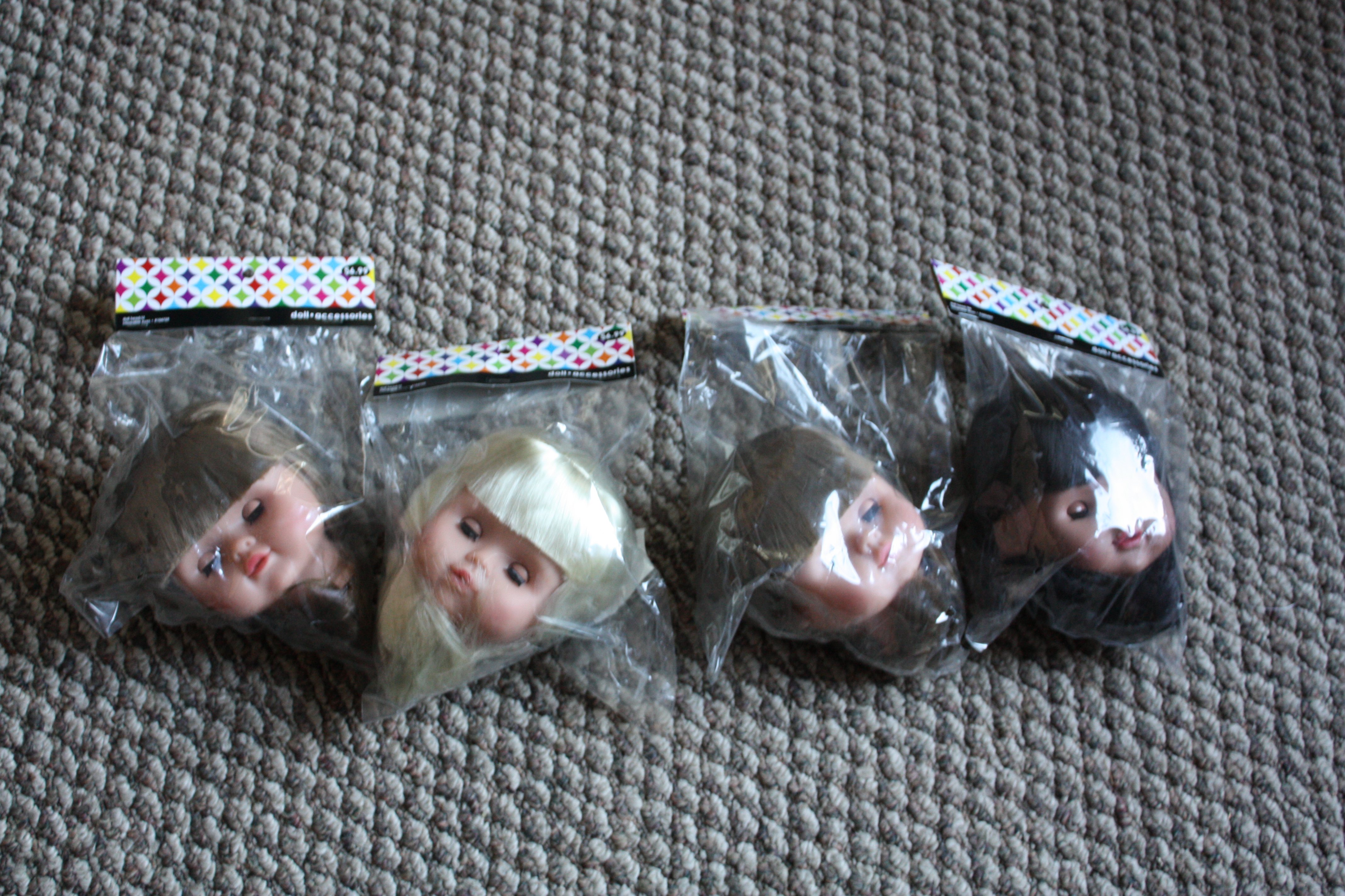
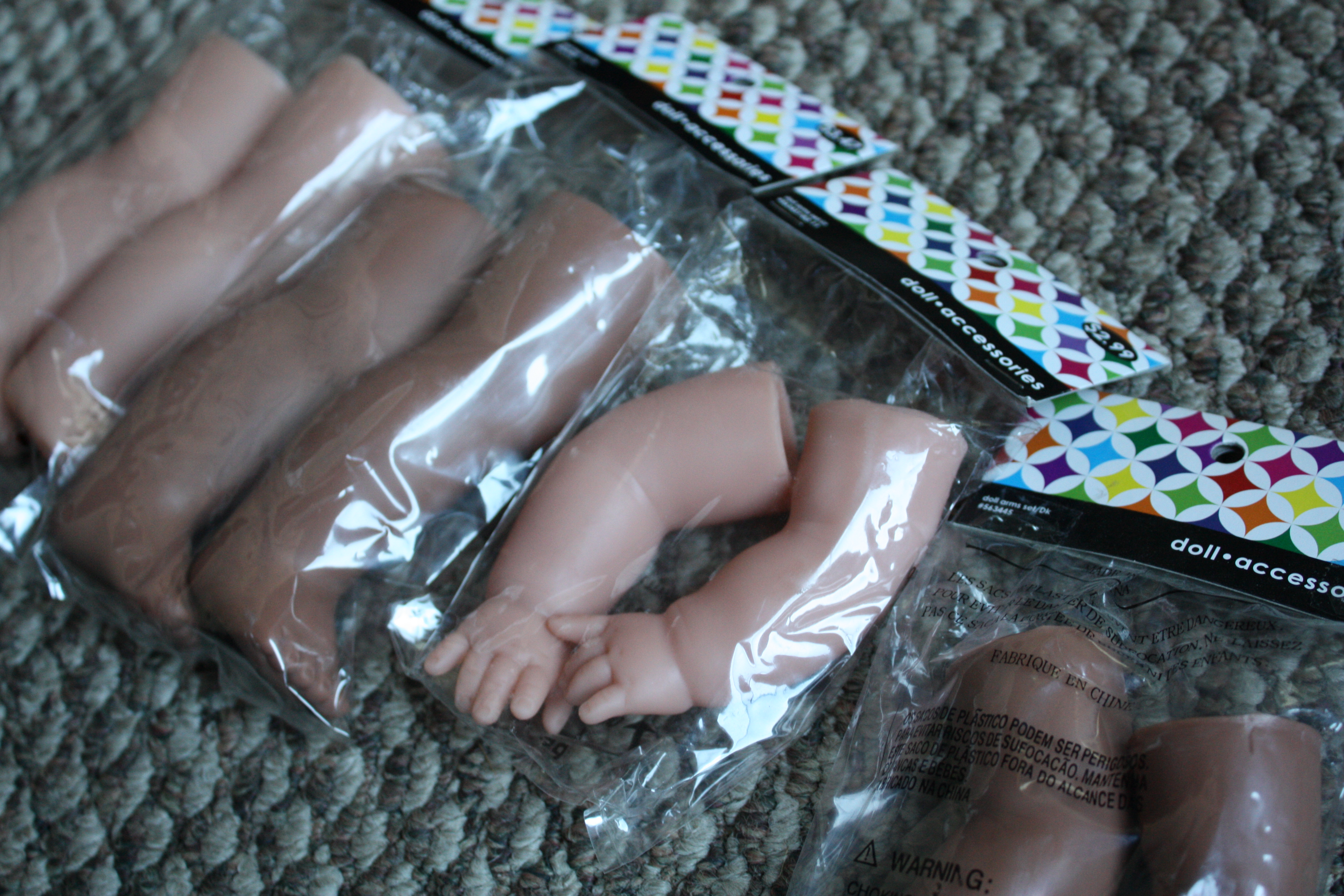
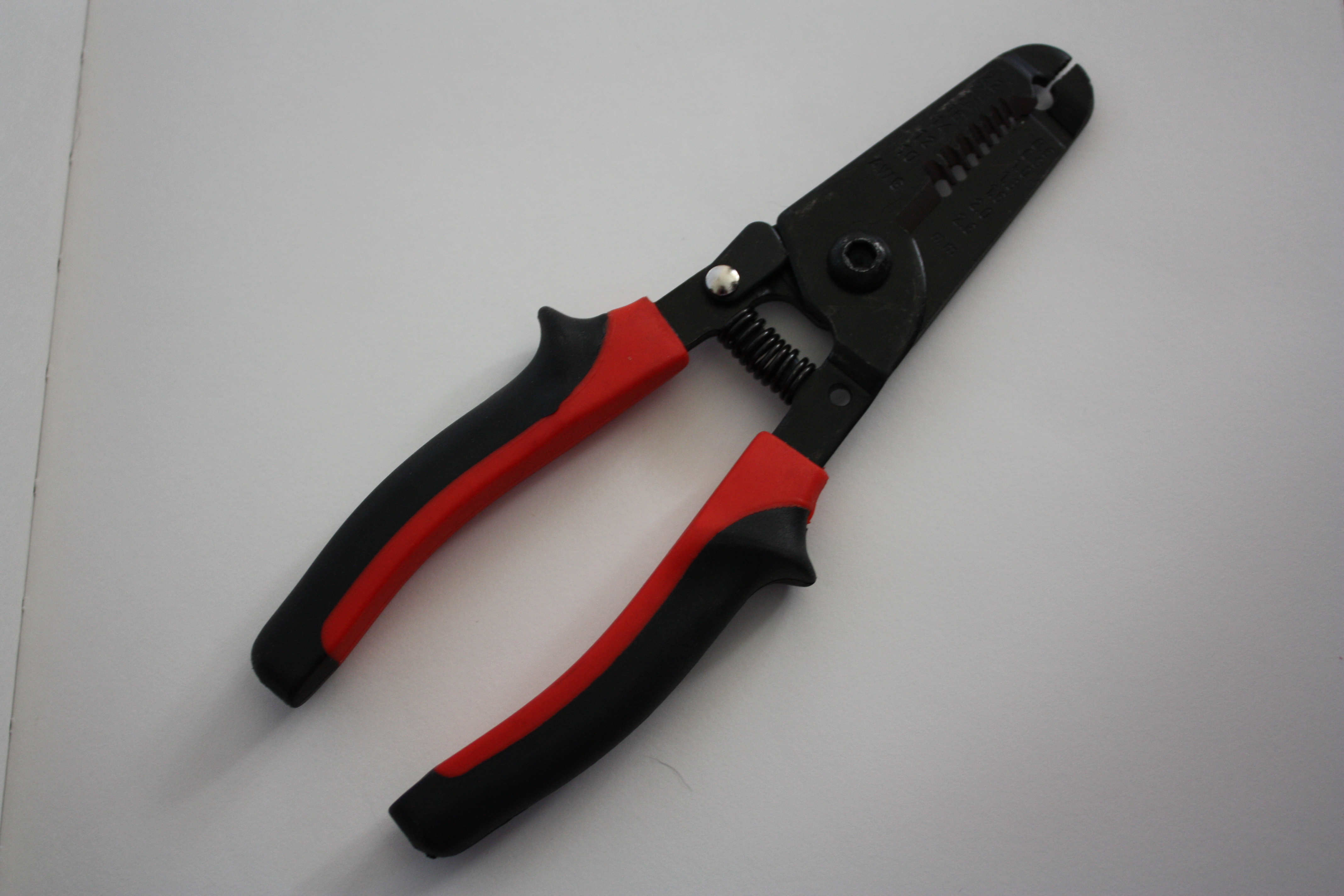
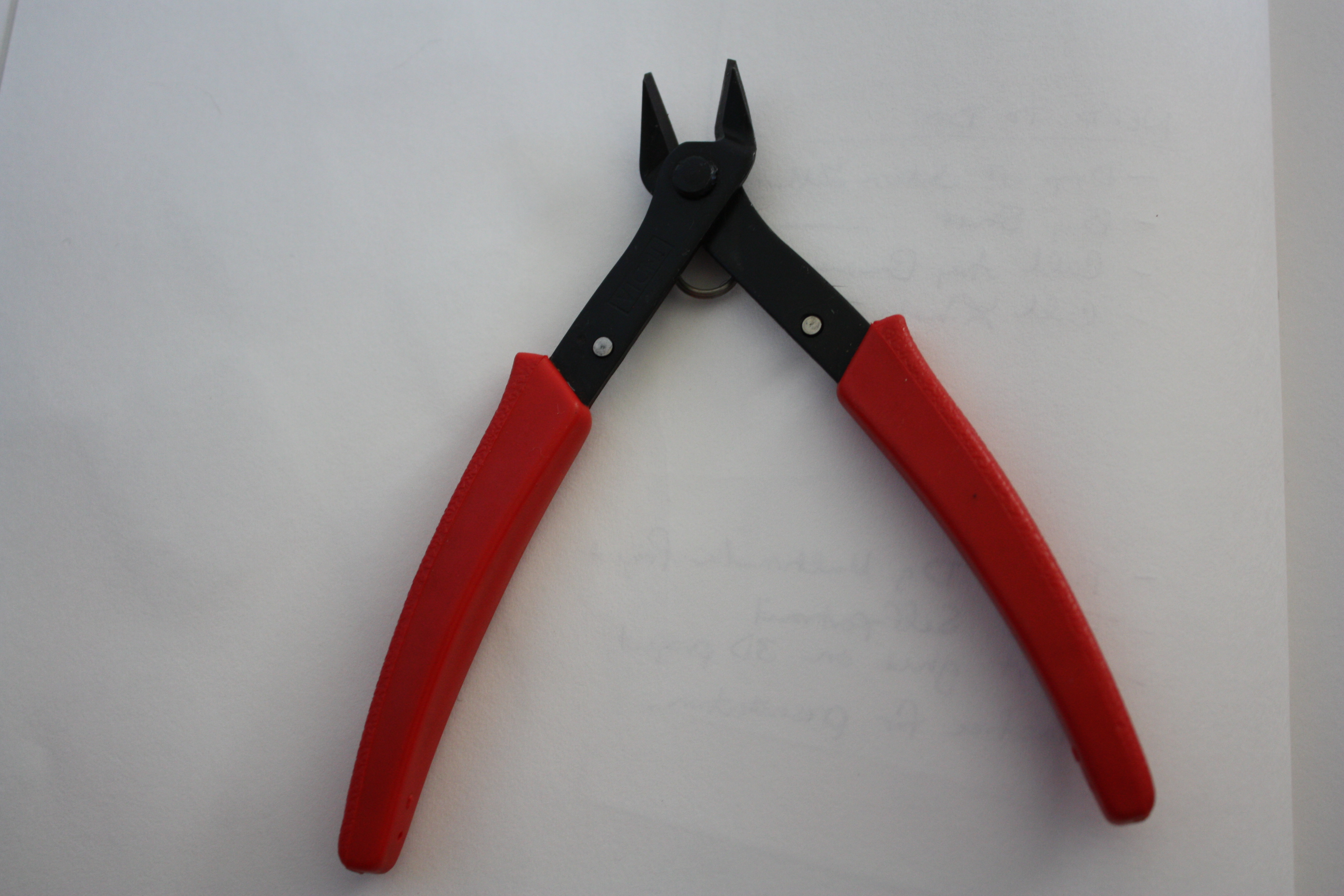
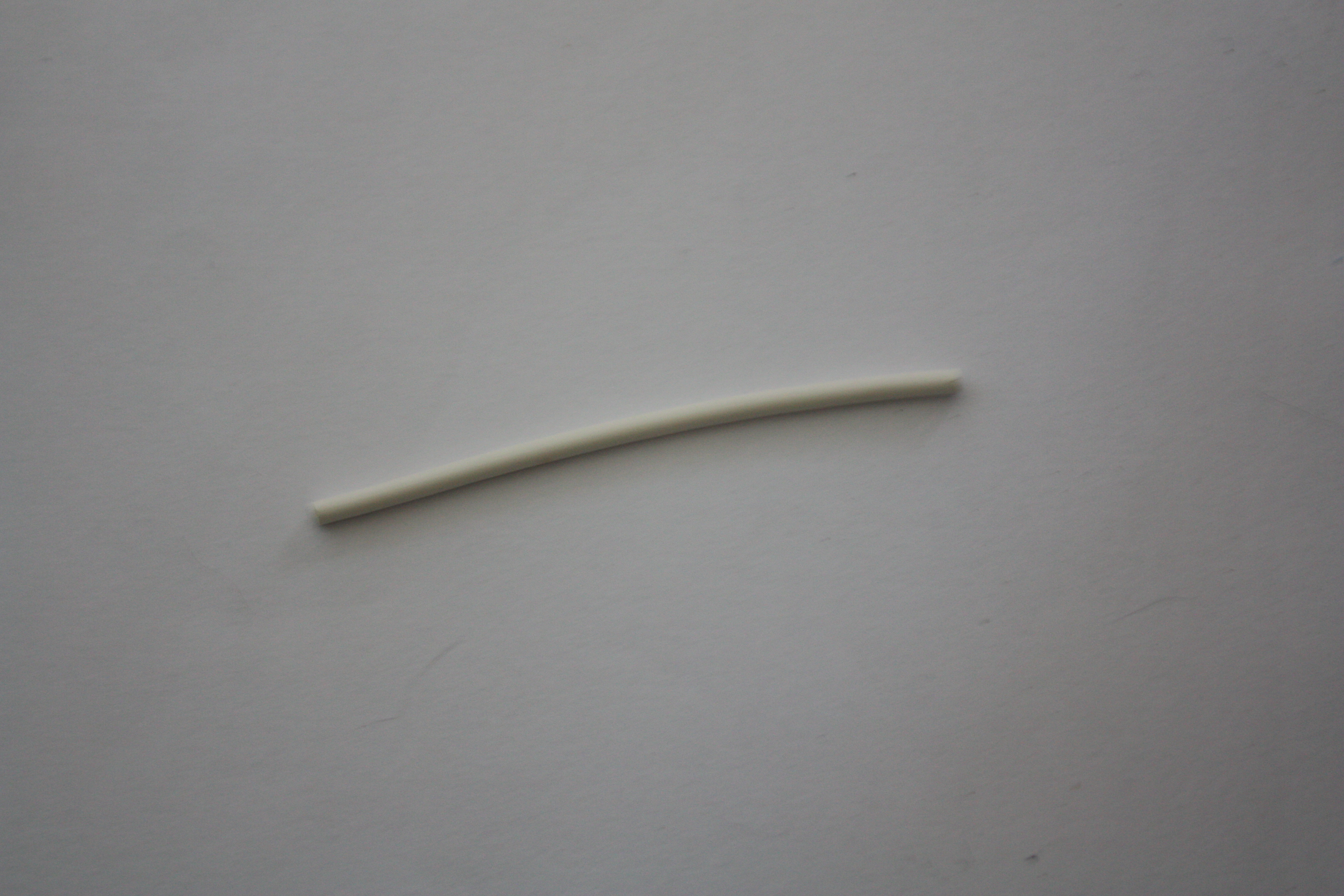
Parts / Supplies:
- Arduino Uno
- Blue Through-Hole LEDs: $17.60 for 100 [Mouser]
^^^I chose these because I like blue, and these ones are extremely bright which I prefer. Bot1398 goes into more detail if you'd like a different color.
- HEATSHRINK FP301 1/8" WHITE: $2.23 for 5ft [Digi-Key]
- WIRE, 20AWG, STRN, WHITE: $10.95 for 100ft [Jameco]
^^^It doesn't matter what color you get, and if I were to do this again, I would actually use 2 different colors instead of one.
- USB Cable A-B: $5 for 6ft [Big Lots]
- Solder wire [Wal-Mart]
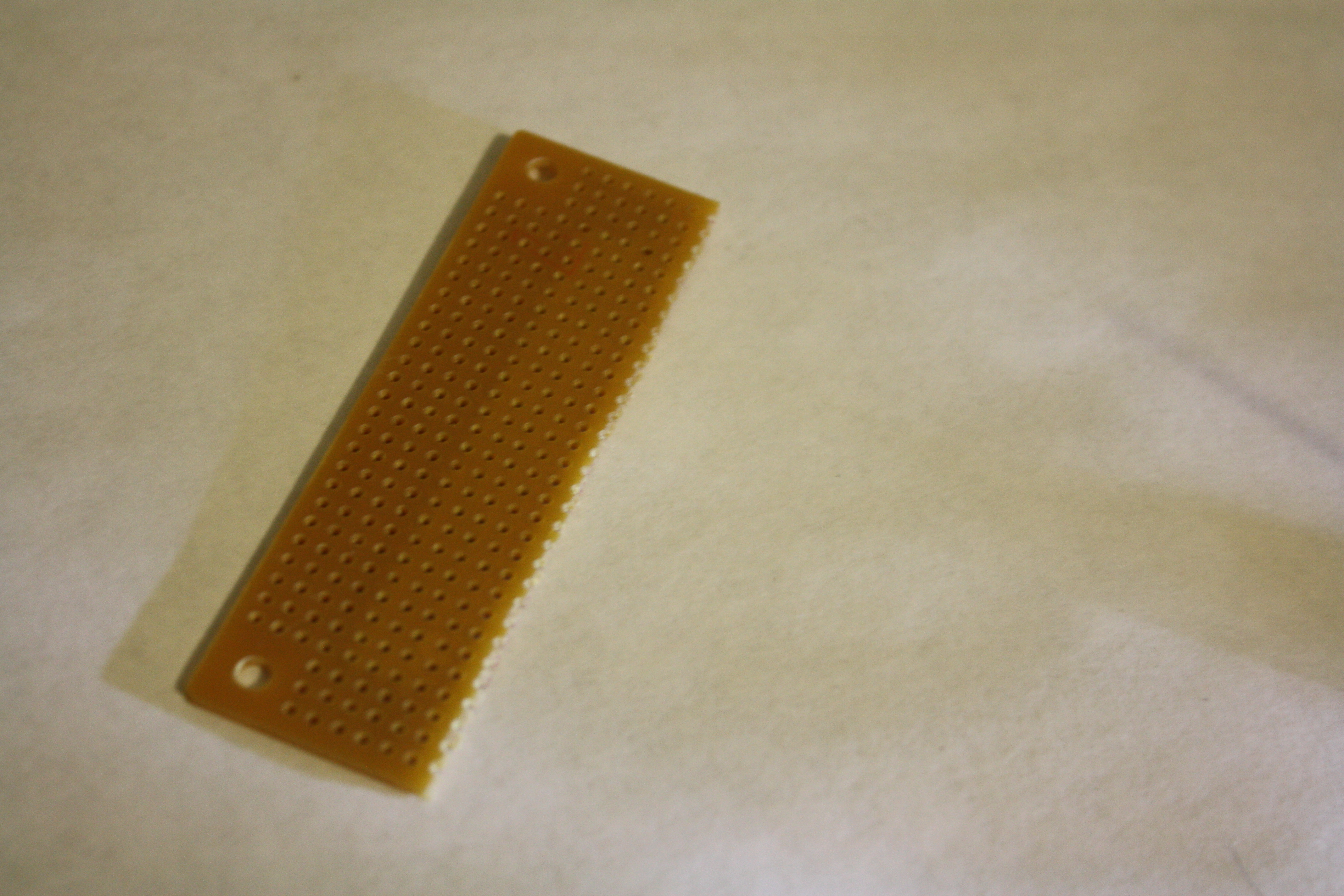
- Plain Solder Board [Not sure where to get it, my teacher gave it to me]
- Super Glue [Wal-Mart]
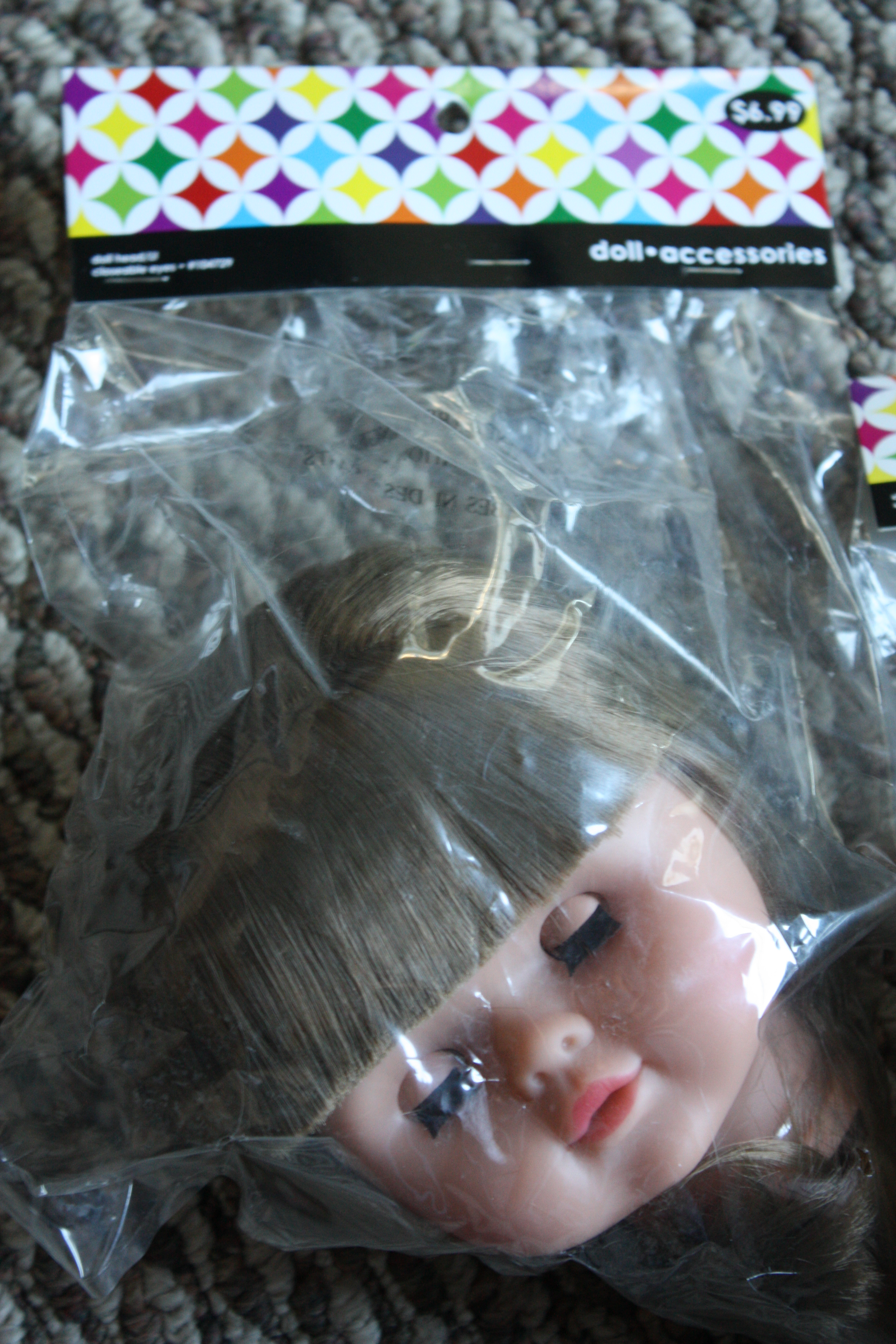
- Baby Doll Heads [Thrift Stores, Goodwill, or Hobby Lobby]
- Baby Doll Body Parts [Thrift Stores, Goodwill, or Hobby Lobby]
- Round Metal Wall Art: $9.98 on Clearance [Target]
- Natural Jute Brown Twine [Hobby Lobby]
- Huge plastic canvas needle [Hobby Lobby]
^^^ These items are only needed if you find Round Metal Wall Art!
- Lighter to burn baby dolls (OPTIONAL)
Tools:
- Multimeter
- Breadboard
- Flashlight
- Arduino Uno
- Arduino Software
- Drill
- Soldering Iron
- Wire Strippers
- Wire cutter
- Arduino Uno
- Blue Through-Hole LEDs: $17.60 for 100 [Mouser]
^^^I chose these because I like blue, and these ones are extremely bright which I prefer. Bot1398 goes into more detail if you'd like a different color.
- HEATSHRINK FP301 1/8" WHITE: $2.23 for 5ft [Digi-Key]
- WIRE, 20AWG, STRN, WHITE: $10.95 for 100ft [Jameco]
^^^It doesn't matter what color you get, and if I were to do this again, I would actually use 2 different colors instead of one.
- USB Cable A-B: $5 for 6ft [Big Lots]
- Solder wire [Wal-Mart]
- Plain Solder Board [Not sure where to get it, my teacher gave it to me]
- Super Glue [Wal-Mart]
- Baby Doll Heads [Thrift Stores, Goodwill, or Hobby Lobby]
- Baby Doll Body Parts [Thrift Stores, Goodwill, or Hobby Lobby]
- Round Metal Wall Art: $9.98 on Clearance [Target]
- Natural Jute Brown Twine [Hobby Lobby]
- Huge plastic canvas needle [Hobby Lobby]
^^^ These items are only needed if you find Round Metal Wall Art!
- Lighter to burn baby dolls (OPTIONAL)
Tools:
- Multimeter
- Breadboard
- Flashlight
- Arduino Uno
- Arduino Software
- Drill
- Soldering Iron
- Wire Strippers
- Wire cutter
Step 2: Code the Arduino
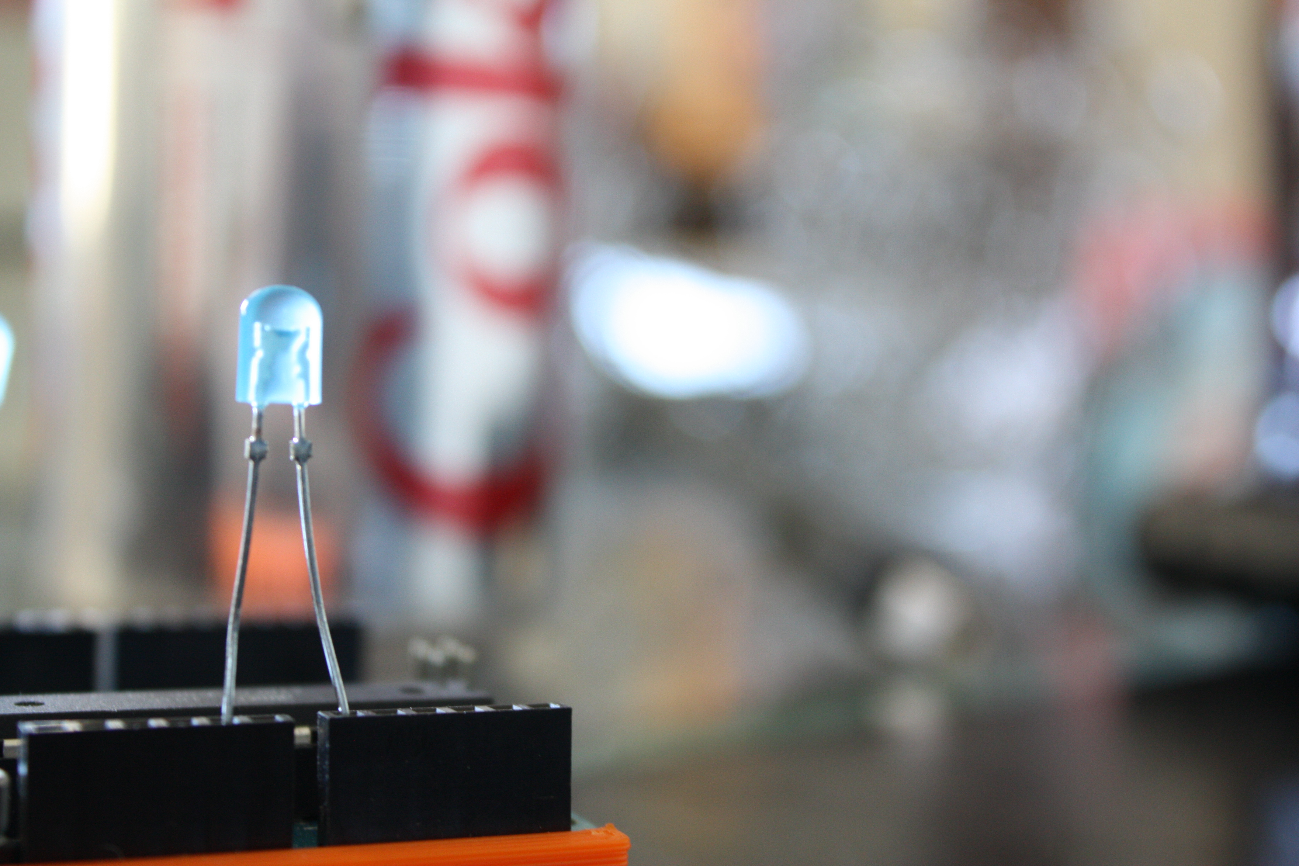
***This is Bot1398's exact code, the only thing I changed was the threshold level.
In this code for the Arduino Uno, we are using the LED as the light sensor, and it acts as a resistor. I have only tested this code for the Arduino Uno, so some adjustments might need to be made for other versions.
The code for LED _sensor_ sensitive_ to_ light:
int sensorLED = 0 ; // LED as sensor connected to analog pin 0
int LED = 13 ;// LED connected to digital pin 13
int LED2 = 12;// LED connected to digital pin 12
int LEDval = 0 ;//Variable to store the the LED sensor value
int light = 175 ;//Threshold level
void setup() {
pinMode(13,OUTPUT);
pinMode(12,OUTPUT);
}
void loop() {
LEDval = analogRead(sensorLED);
if (LEDval <= light) { // check if light
digitalWrite(LED2, HIGH); // if light, turn off led
} else {
digitalWrite(LED2, LOW); // if dark, turn on led
}
if (LEDval < light) { // check if light
digitalWrite(LED, HIGH); // if light, turn off led
} else {
digitalWrite(LED, LOW); // if dark, turn on led
}
}
Step 3: Test the Light Out!
You want to make sure that it works! This is where your flashlight comes in handy. You want to make sure that when you have the flashlight on, it turns off. If the flashlight is off, it should turn on. If this does not work - then go back and review the code and placement of the LEDs. If it does work - Great! Onto the next step.
Downloads
Step 4: Umbrella Thingy
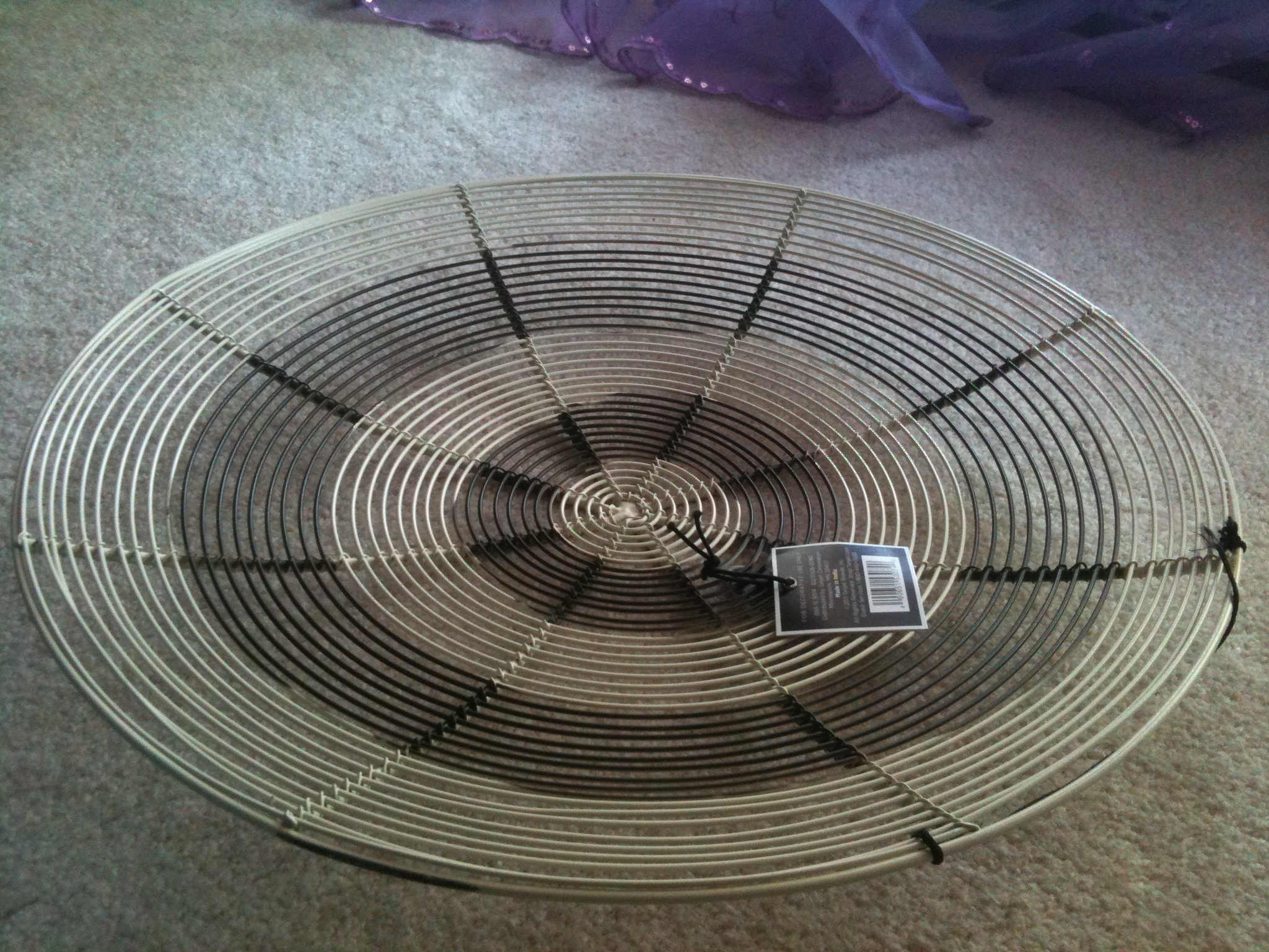
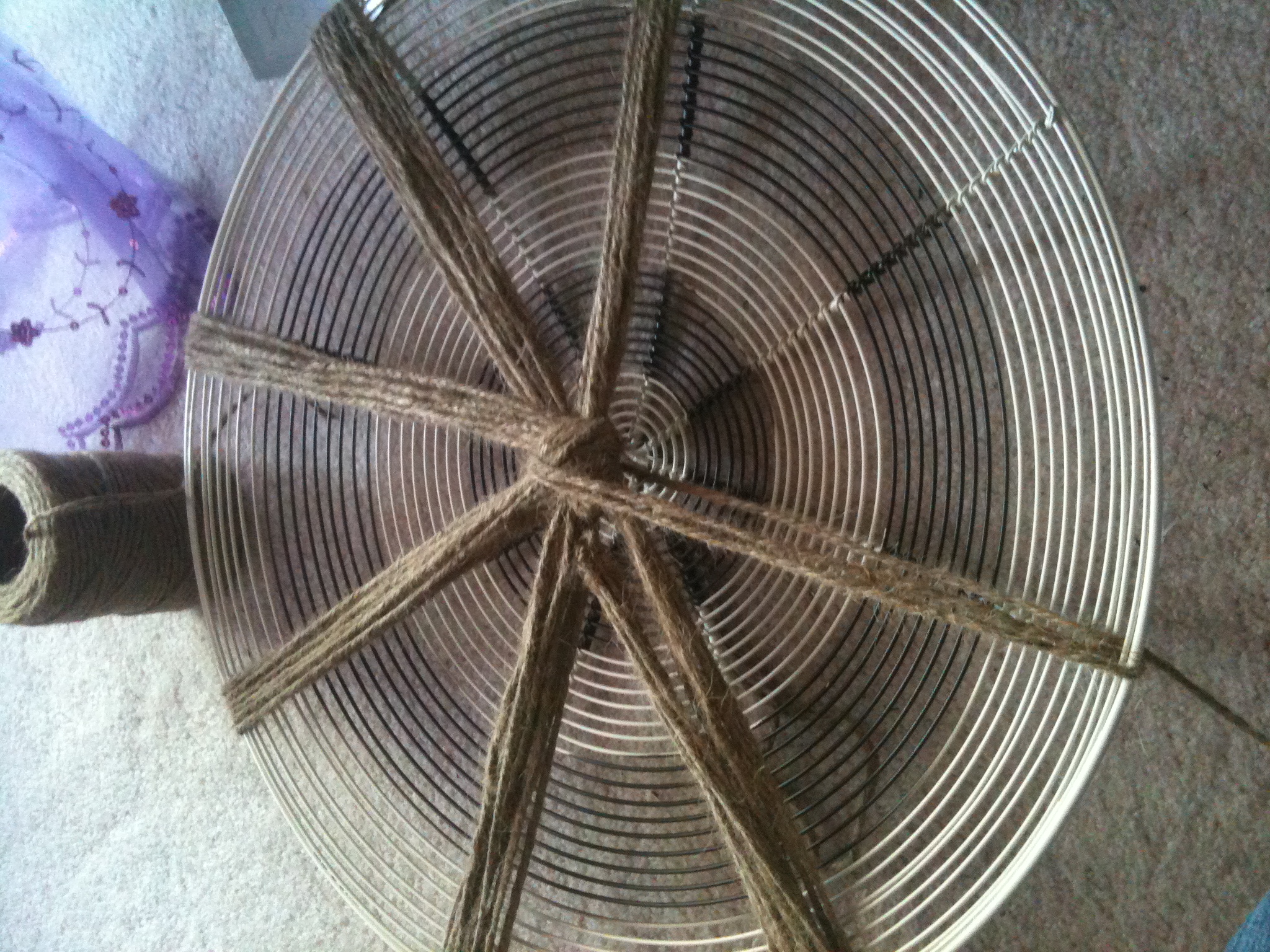
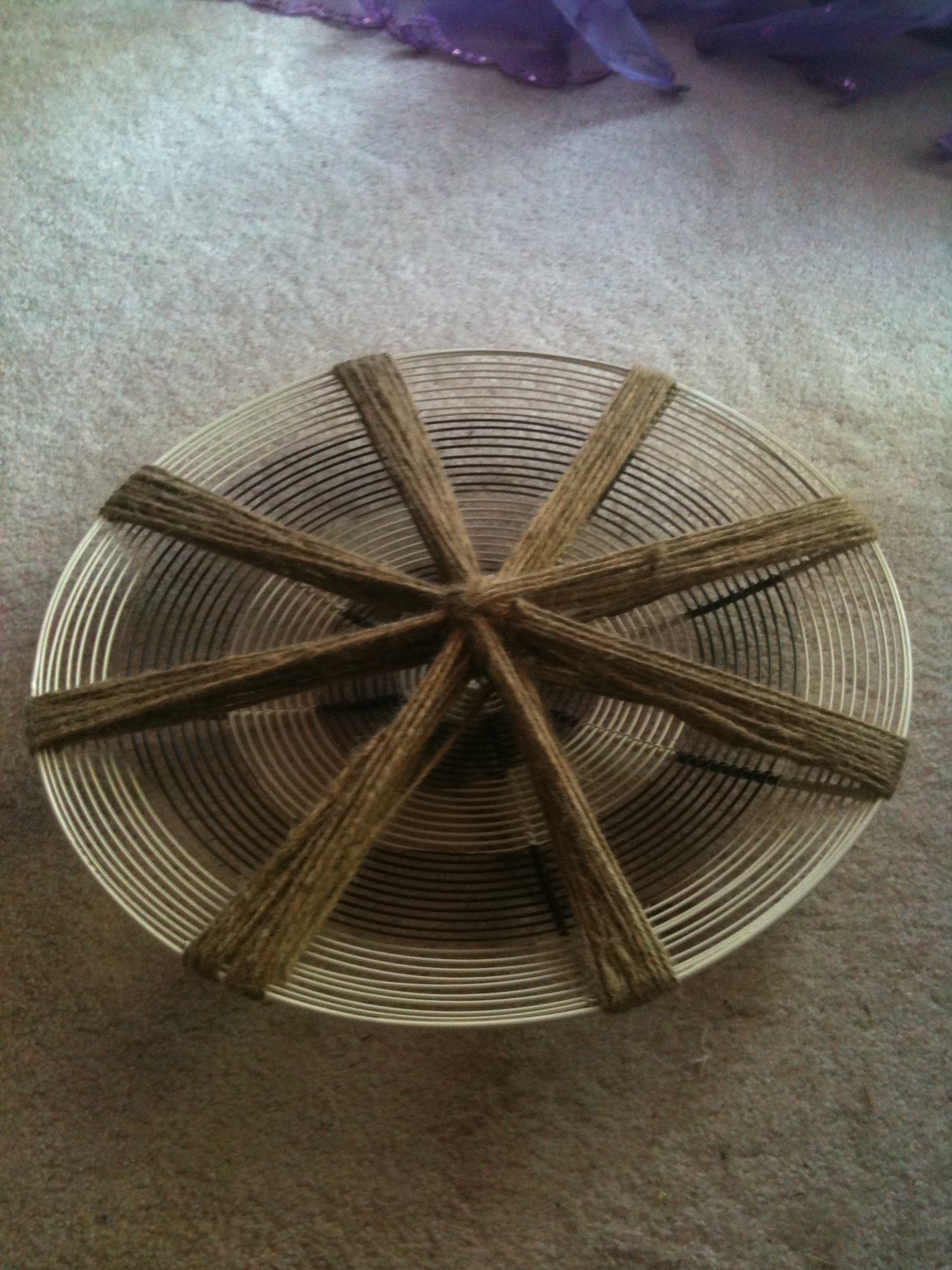
We are moving onto the structual backbone of the night light.
For this, I used "wall art" I found while walking around Target. Anything would really work for this. You could use foam, an old clock, fan, anything to hang these baby dolls from that has a place to hold the Arduino Uno safely and there won't be a lot of movement.
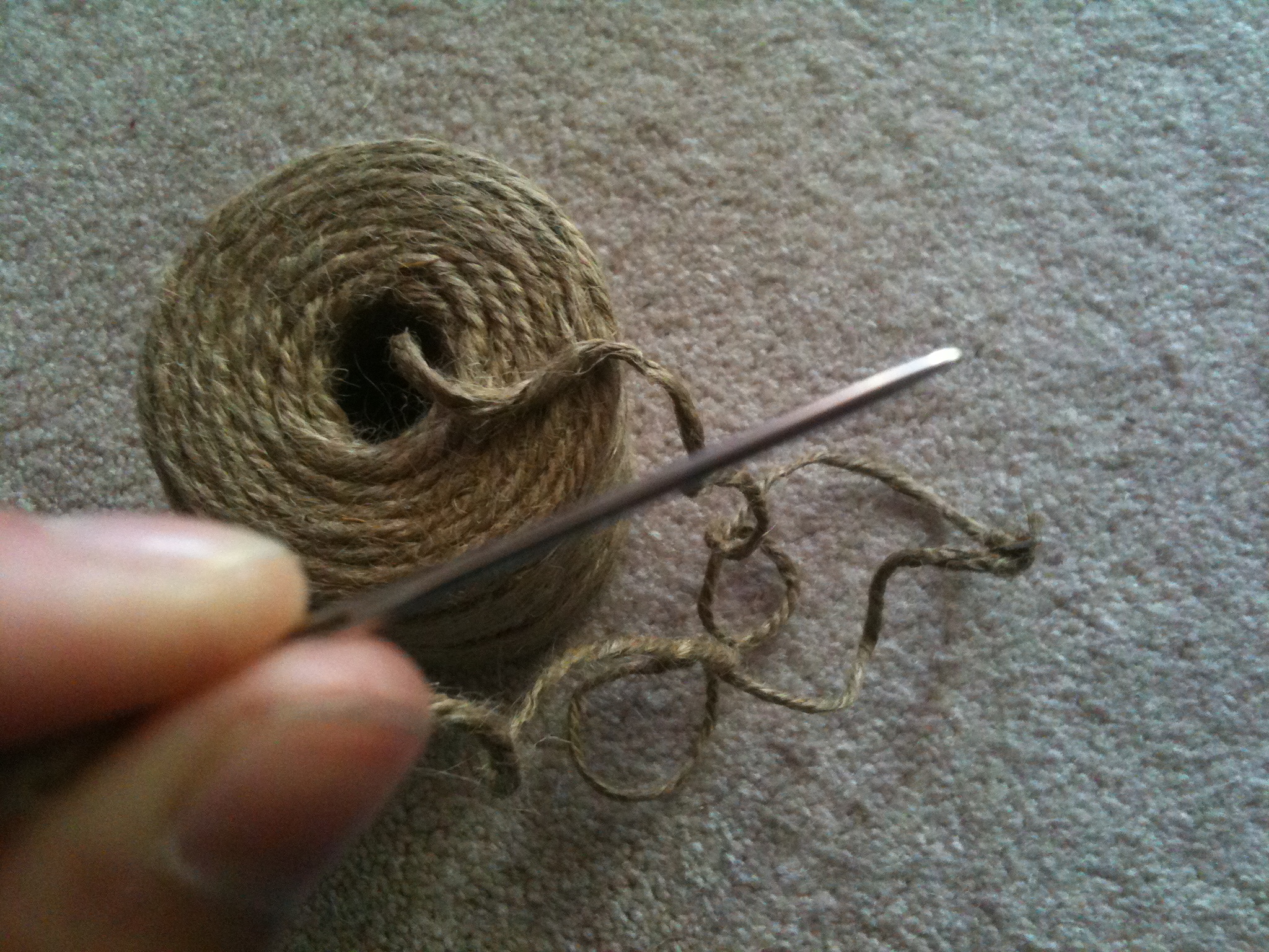
If you happen to find something like this "wall art" and choose to use it, I created a little cradle in the center of it for the Arduino Uno. I simply used Natural Jute Twine to weave from one end of the "wall art" to the opposite side 6 times to get a sturdy line, and then again to make an "X" in the center.
For the rest of the lines, I only went half way to wrap around the center of the "X" and back, continuing in a circle.
At the end, here's what mine looked like.
Step 5: LED Fun!
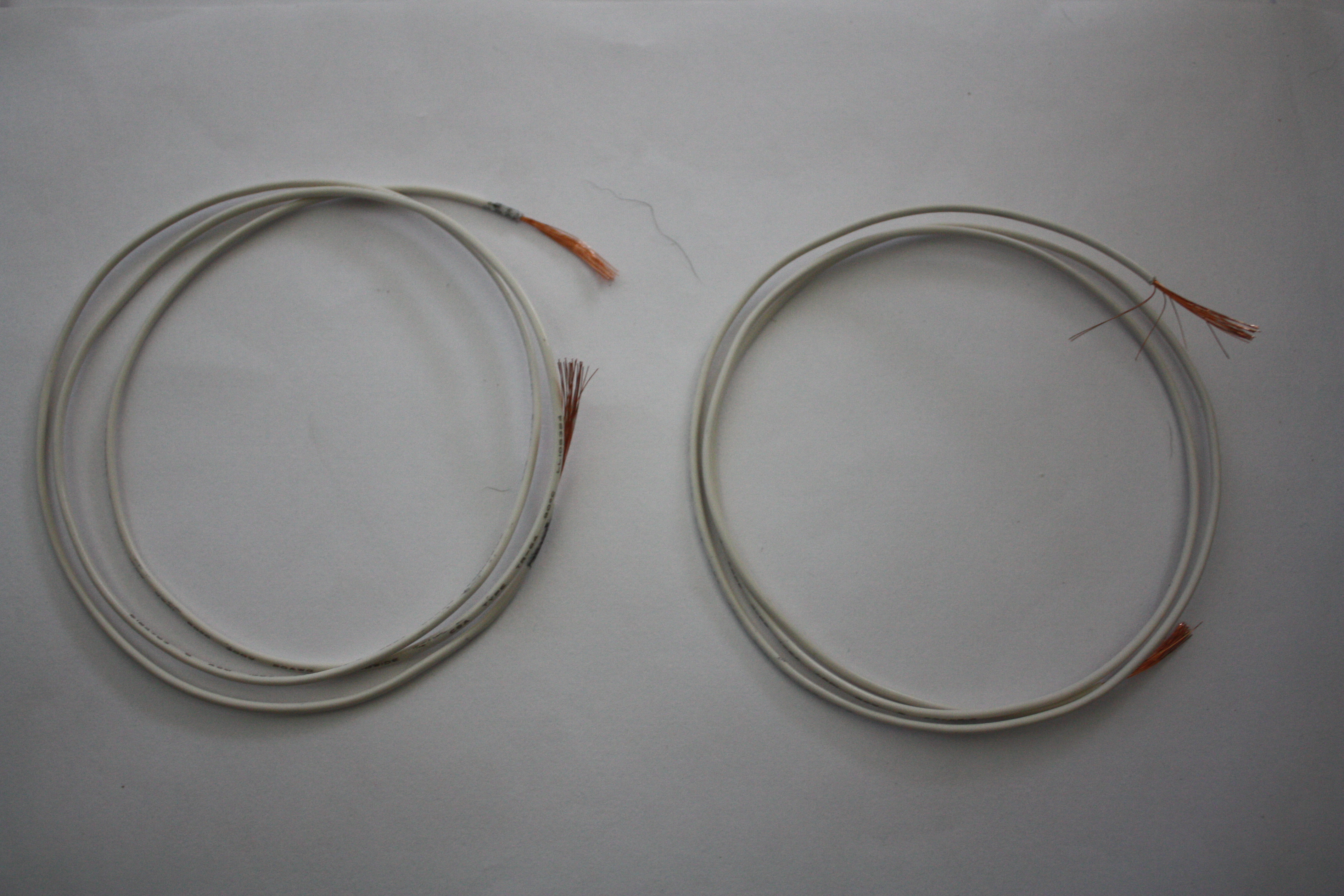
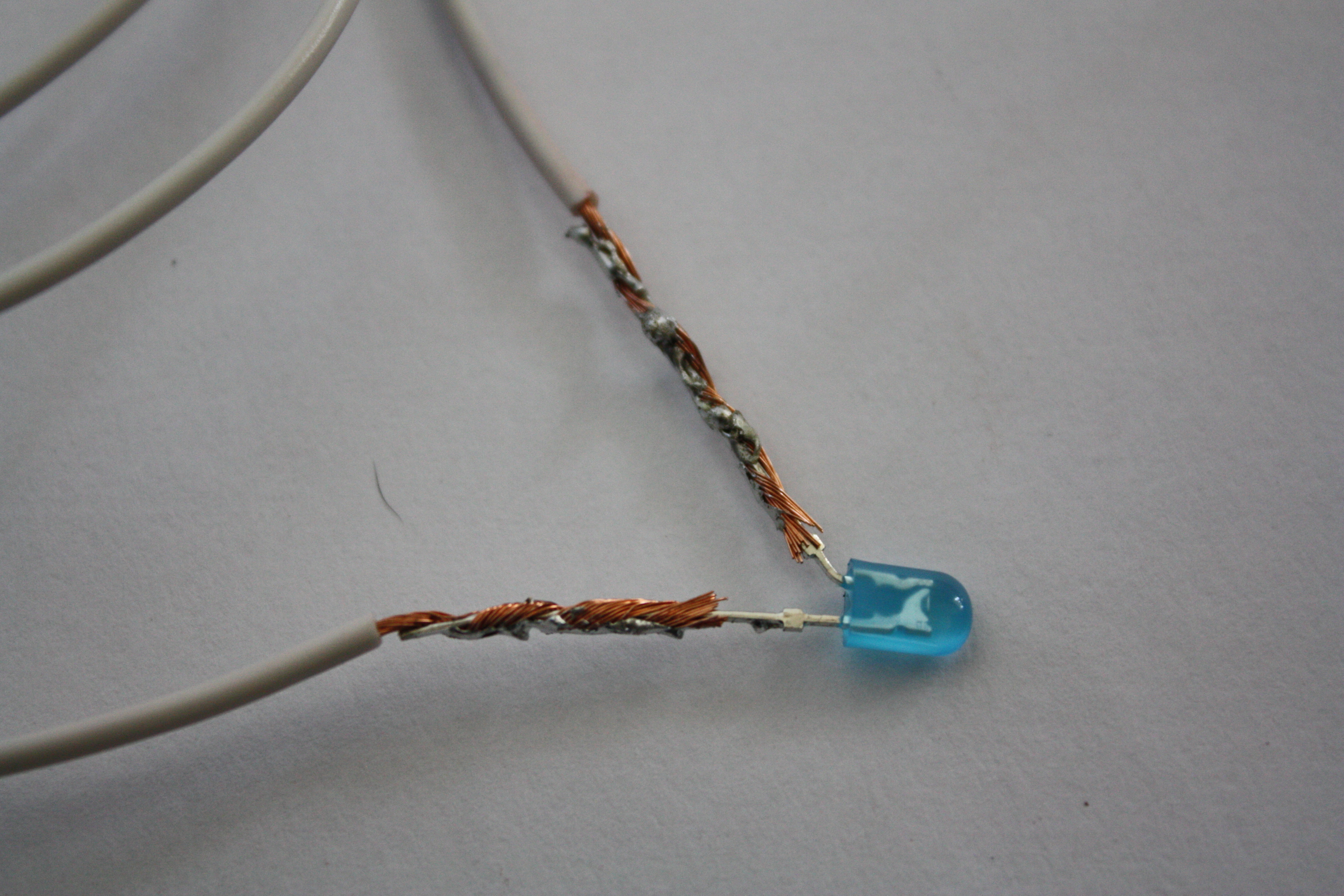

Next, we move onto LEDs.
You need 3 LEDs for each head you have. (2 eyes and 1 for the neck - neck is optional but creepy)
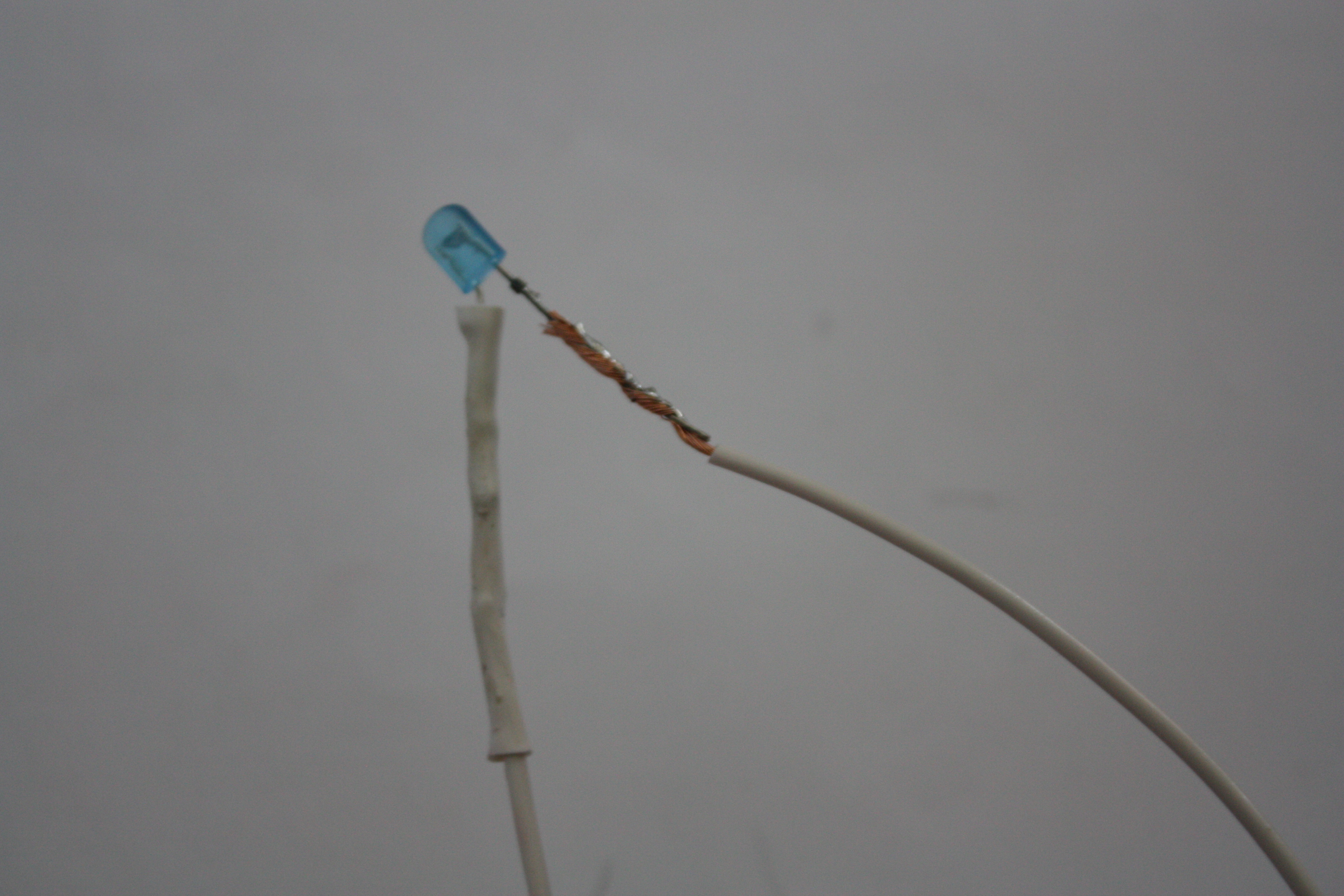
1) I cut about 2 ft of 20awg wire per leg of LED. This is TOO much unless you're like me and terrible at stripping wires! If you're great at stripping wires, you only need about a foot.
2) You need to use your wire strippers and strip both ends of the wires you cut.
3) Take the ends of your wire and carefully wrap them around each leg of the LED. Make sure you keep track of which leg is positive (LONGER LEG) and leg is ground (SHORTER LEG). Using different color wire makes this MUCH easier, and I wish I thought of it before I bought a bunch of one color.
4) Solder the wire and LED positive leg together and then the wire and LED ground leg together. It doesn't matter in which order you sodder them, just keep track of which is which.
5) After that, cut enough of your Heat Shrink to cover the wrapped area, and a little more for extra coverage. The heat shrink will make sure that your connection stays strong and protected.
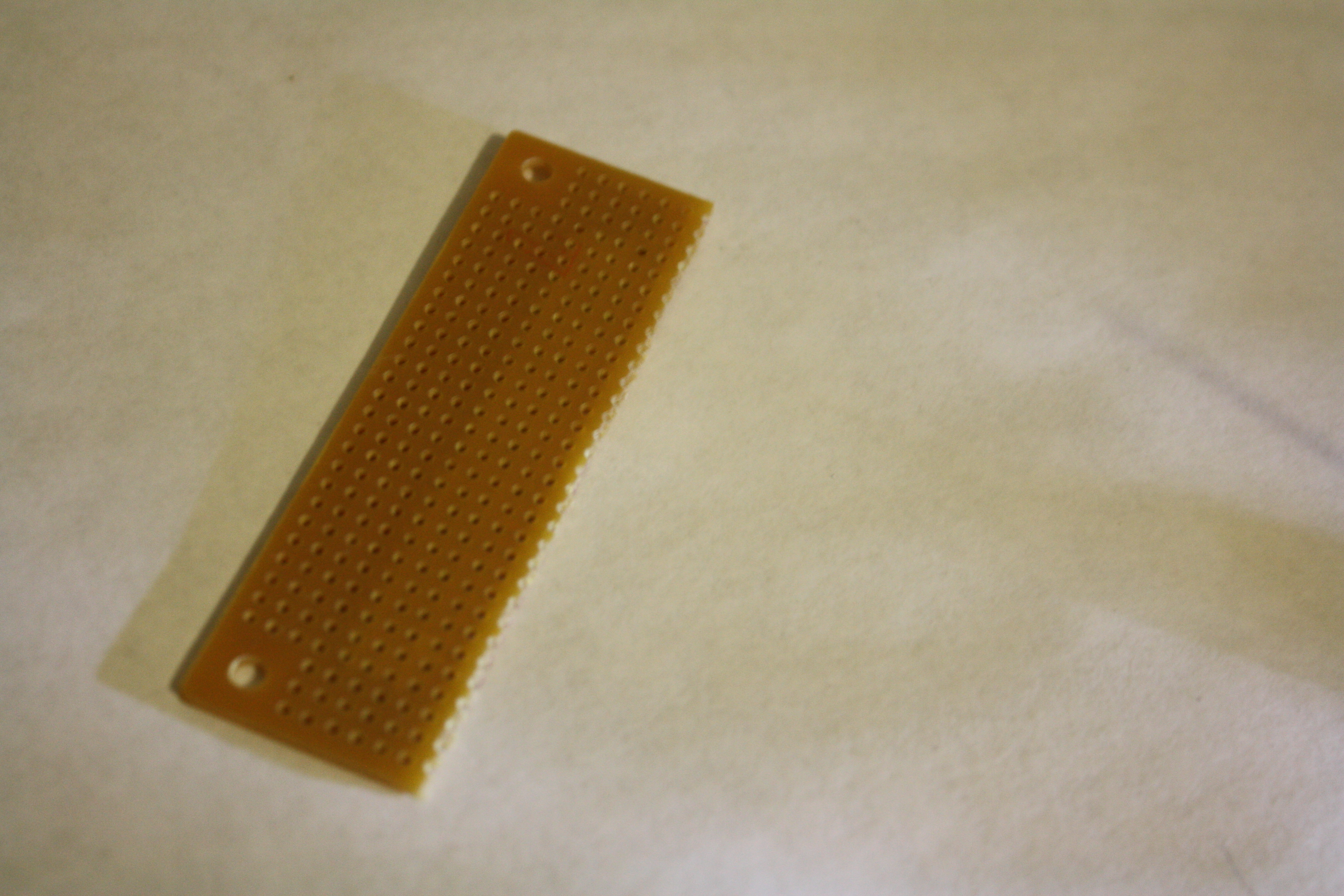
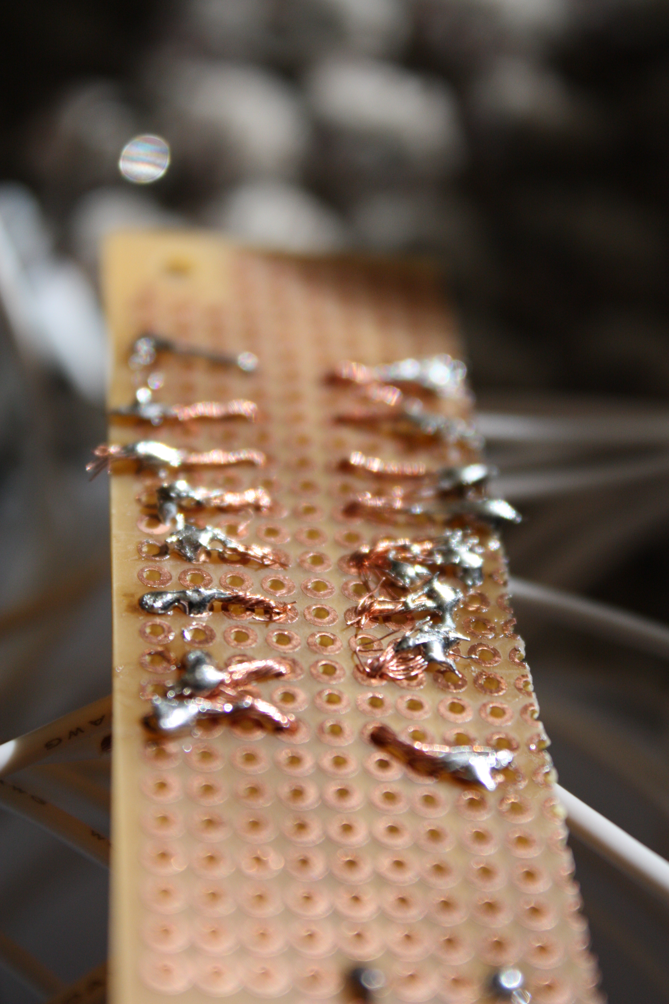
6) Take the plain solder board and designate a row to positive LED legs and another row to ground LED legs. You will sodder on the ends of the wire, but not where board and wire meet. You need this extra wire so you can run a single power wire and a single ground wire along all of them. It makes it a lot easier in the end and less wires (and we already have a mess of wires.) 2 different color wires really make this easier.
7) After you get done with all the LED business, next step.
Step 6: Power!
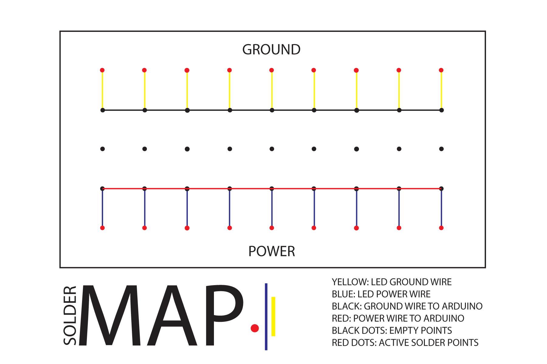
Okay, so now we need to cut wire so the LEDs can get some power.
I cut about 4 inches for both ground and power wire. One side, I stripped a regular amount, about 1/2 an inch. The other side, I stripped about 2 inches.
After cutting the wire, you will need to solder the 2 inch exposed wire to your board of LED wires! Since you have two rows dedicated to each, you only need to set it on one row and solder away.
You're going to do this twice, one for power / positive and the other for ground.
After you're done soldering, you can put the power and ground wires back into the Arduino and you're ready for business.
Step 7: Dirty the Baby Dolls! [Optional]
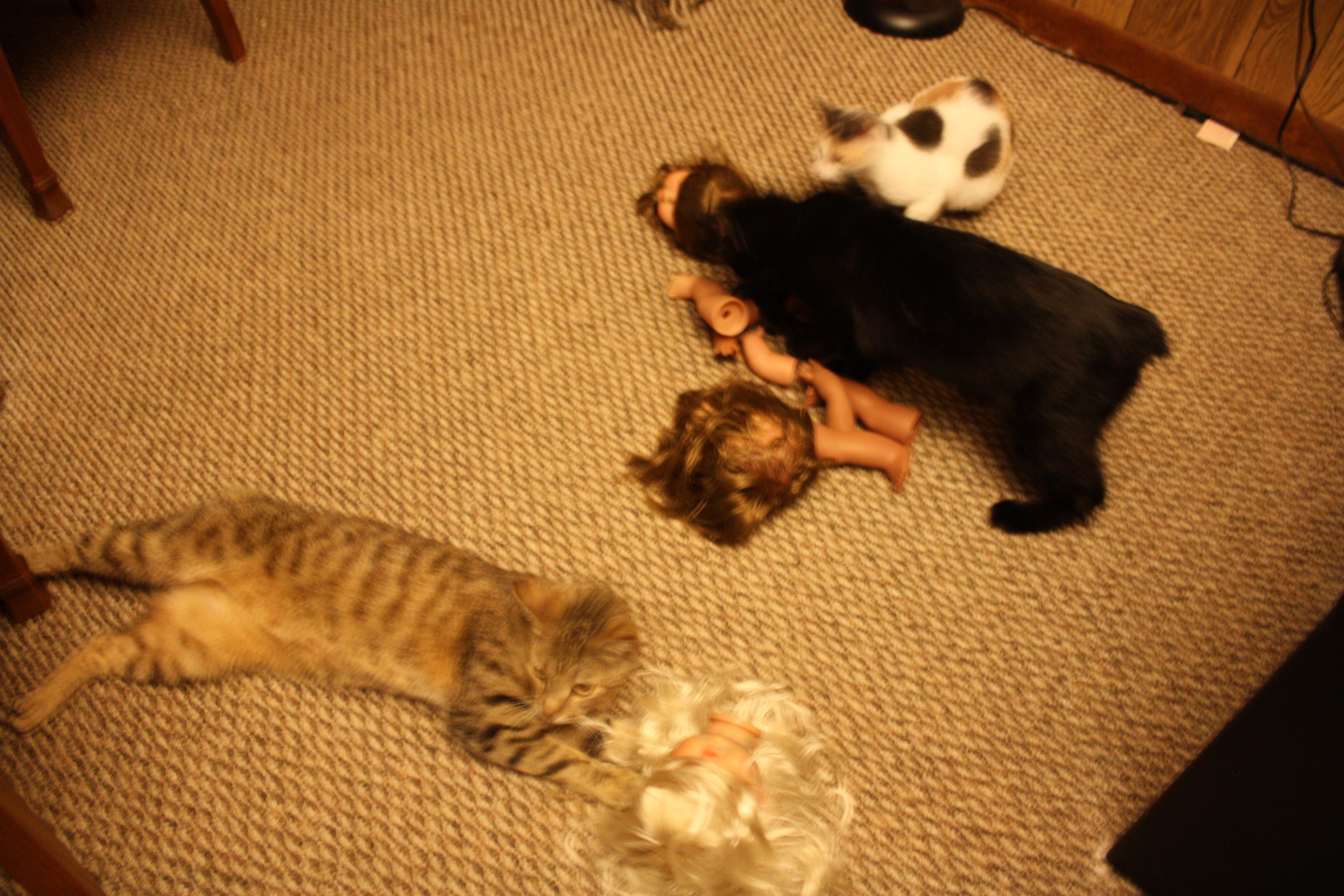
THIS STEP IS OPTIONAL!
This is extremely fun! My cats destroy everything, so I gave them the baby doll parts to destroy as well. At first they didn't want anything to do with them, but a little catnip fixed that.
Afterwards I rubbed the parts in the dirt to get them really gritty looking and then I used a lighter to burn the pieces. Be careful when you are using fire!
Step 8: Drill Into Baby's Heads

After you are done dirtying them (or keeping them clean, however you like it), drill 3 holes into the back of the neck and into the eyes. We are going to put the LEDs in the eyes.
This is probably the most time consuming part, it takes forever to take out their eyes.
This is probably the most time consuming part, it takes forever to take out their eyes.
Step 9: Insert LEDs
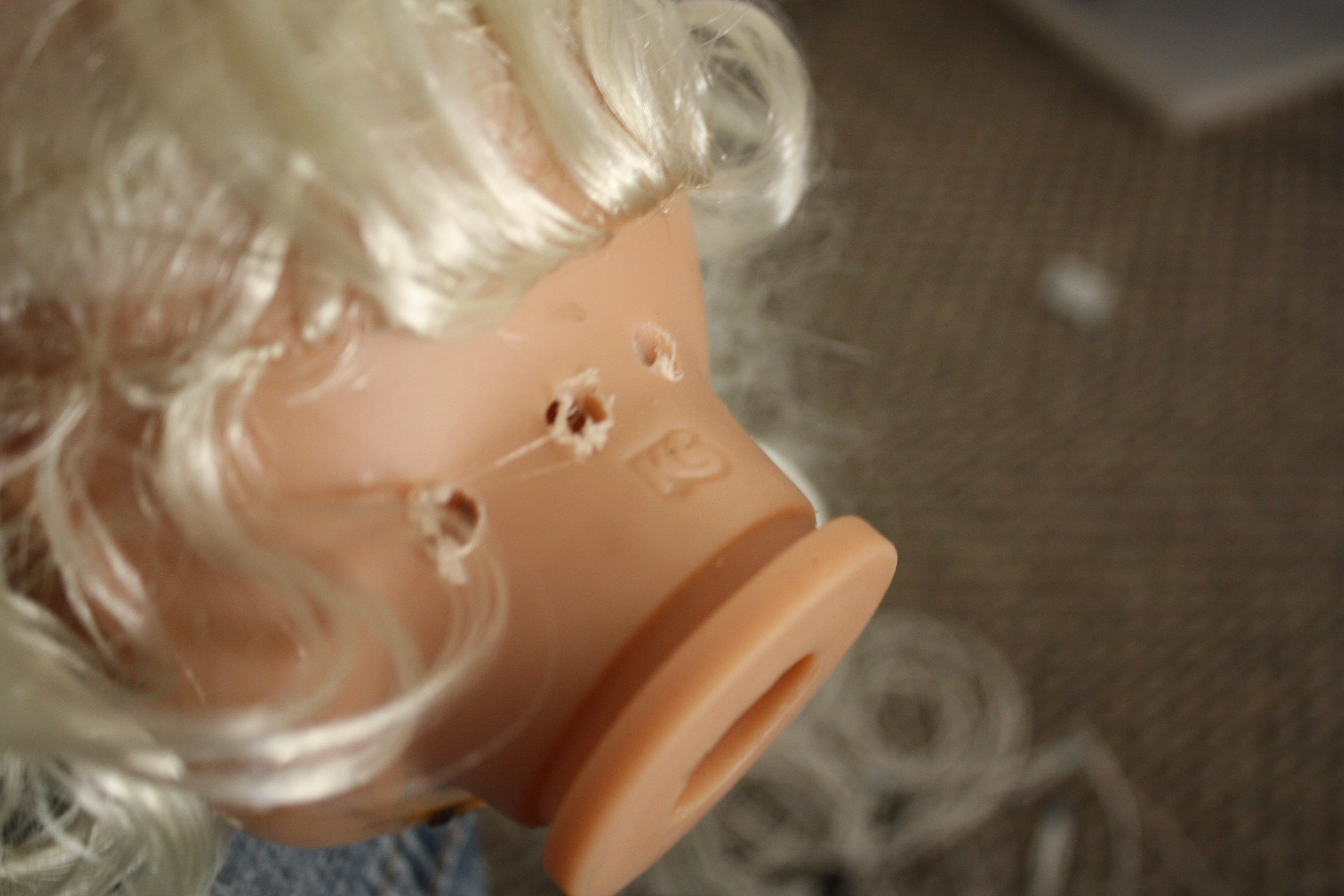
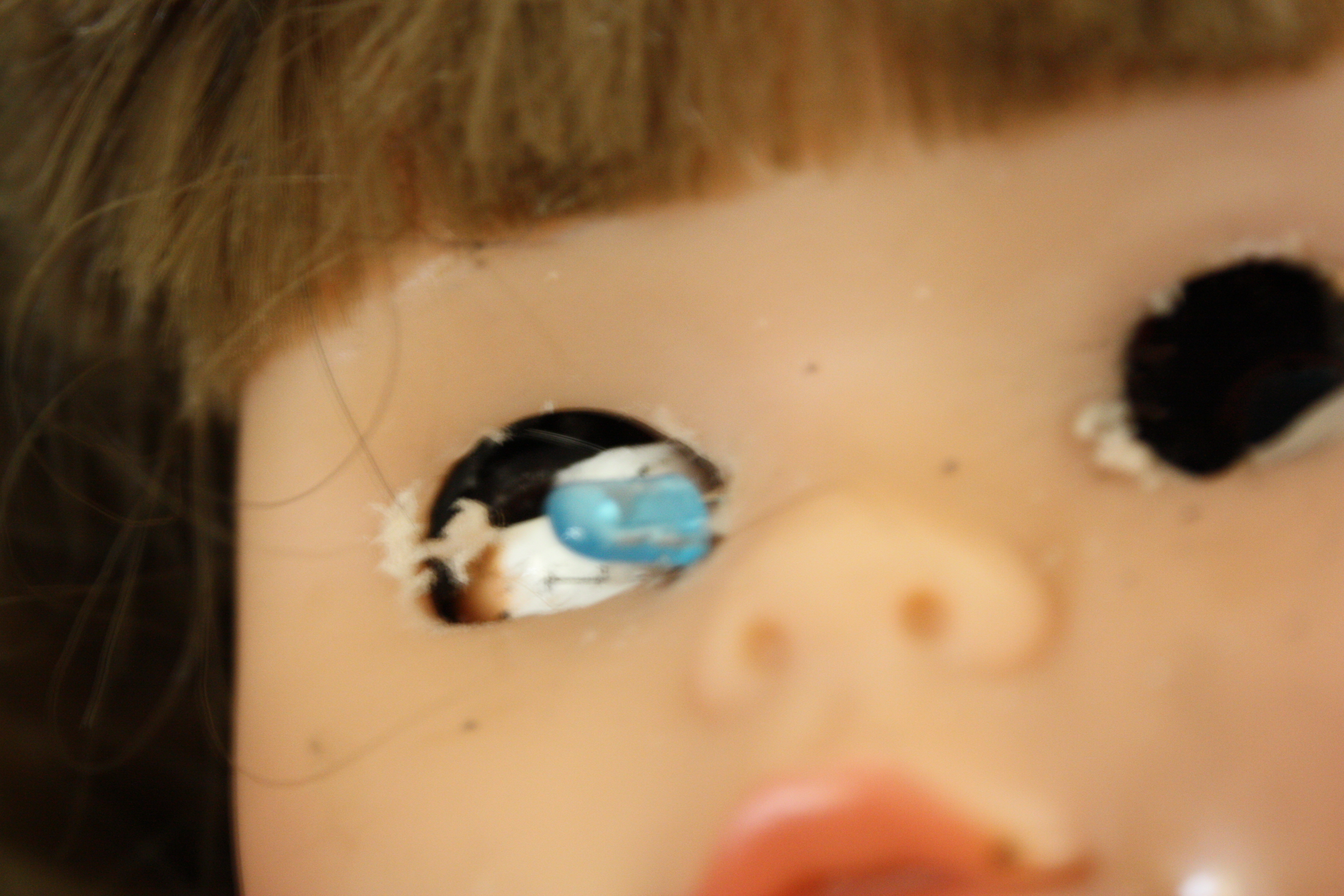
The entrance for the LEDs are the 3 holes drilled into the back of the neck - one for the neck and two for the eyes.
It wasn't too hard to get the LEDs in there, it was just a lot of wiggling. I even used some pliers to get the LEDs into the eye socket, but be very careful not to disturb the wires.
It wasn't too hard to get the LEDs in there, it was just a lot of wiggling. I even used some pliers to get the LEDs into the eye socket, but be very careful not to disturb the wires.
Step 10: Make It Pretty!
Put any extra wires into the back of the head, there's plenty of space. Rearrange everything how you want it! :) Make sure that the LED is exposed because it's your light sensor.
I put arms and legs with super glue all over my night light to make it extra creepy as my final touches..
I put arms and legs with super glue all over my night light to make it extra creepy as my final touches..