Beginners Guide to 3D Modelling Ft.Tinkercad
by godtrinav in Teachers > 3D Design
1311 Views, 6 Favorites, 0 Comments
Beginners Guide to 3D Modelling Ft.Tinkercad
.png)
A few months ago, I was planning to design a 3D model of an atom to give students a much better visual and idea of the atomic structure of the atom. While I was in search of a free, easy to use 3D modelling tool, I came across Tinkercad — a free, beginner-friendly tool by Autodesk, used to design 3D models, circuits, and various other things. It's just like a mini/easy version of Autodesk Fusion, which is a tool that has more functionality and flexibility compared to Tinkercad. But if you are a beginner, I would suggest you start your 3D modelling journey with Tinkercad as it's much easier and user-friendly.
We will master the fundamentals of Tinkercad in this tutorial. So let's get started on the tutorial!
Supplies

Tinkercad - https://www.tinkercad.com/
Computer
Setting Up Tinkercad
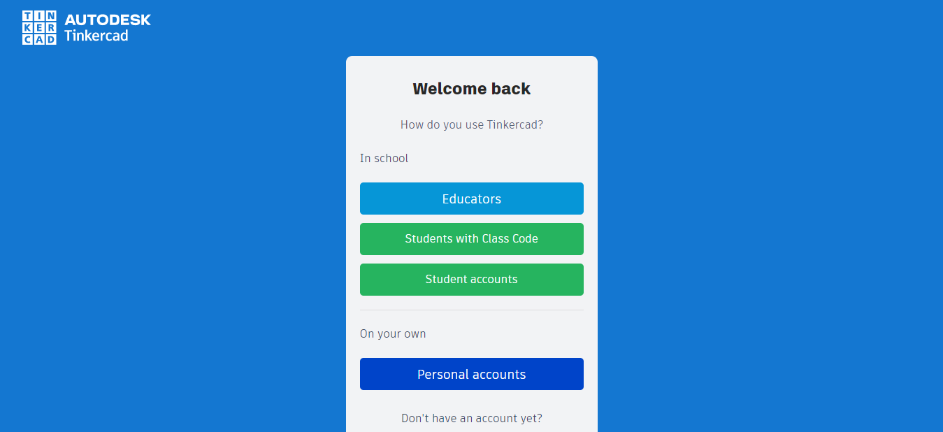
Tinkercad is a user-friendly, free website that makes it simple to create models for 3D printing. Making a user account on Tinkercad is the first thing you should do. You'll be able to do this to preserve your creations in your individual account. You'll have to supply some basic information, so make sure your password is something you can remember.
Setting Up the Project

Click the blue "Create New Design" button to start a new project.
Workspace
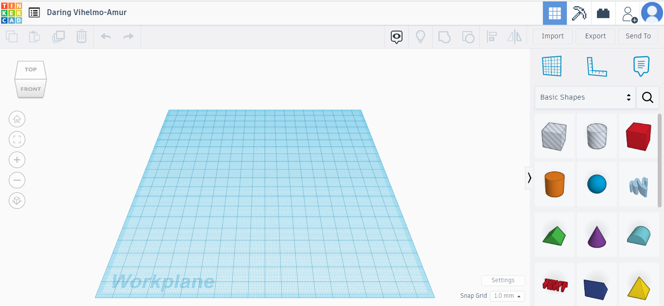

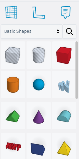
There will now be a form library to the right and a blue workplane. You'll also notice that Tinkercad automatically creates a clever name for your new design (visible in the top left corner), along with a cube to alter the work plane's viewpoint.
Your primary design area is here. The majority of your Tinkercad work will be created in this area. The build plate used by 3D printers is shown by the blue region with grid lines. You should use this plate to creat your artwork.
Getting to Know the Interface
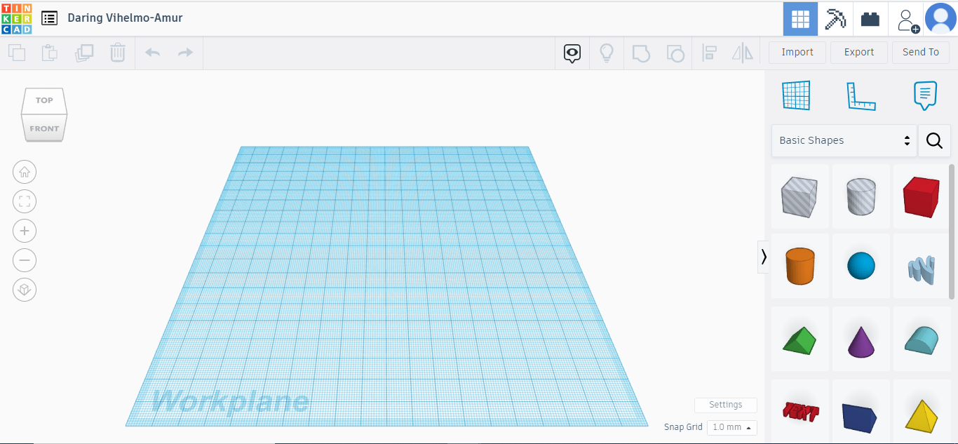
- Top toolbar featuring design operations like "Group" and "Align" on the right and more generic tools like "Copy," "Paste," and "Delete" on the left.
- Tools for basic orienting such as zoom in and zoom out. Note that the mouse wheel can also be used to control these particular tools.
- Shape Panel, which includes all of the basic design elements, such as text and cubes and spheres. (Exploring this box may be enjoyable because it has so many intriguing and occasionally adjustable choices!)
Create a Shape
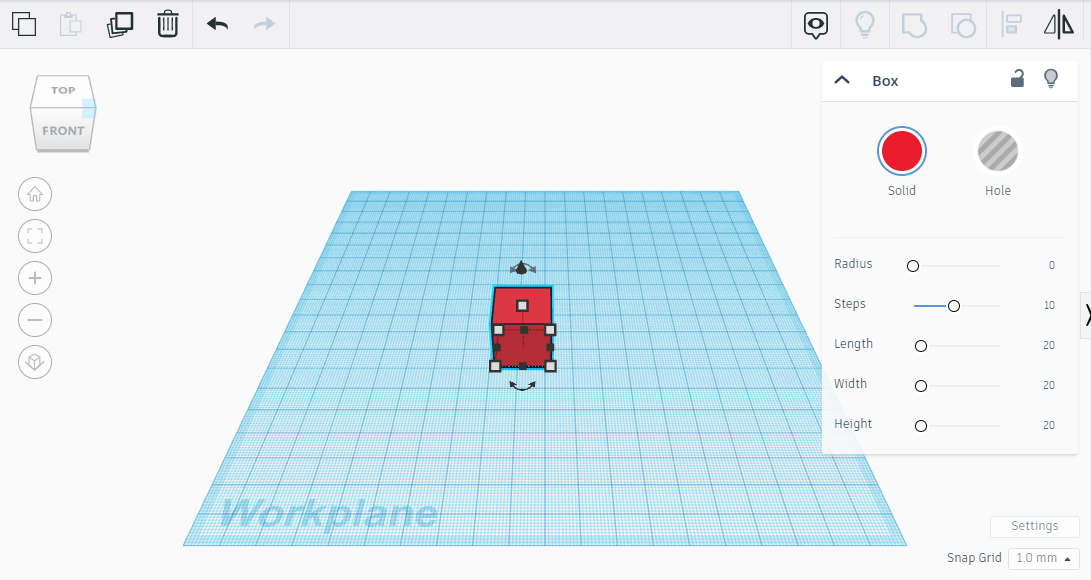
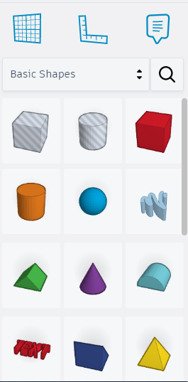
Let's begin by selecting a fundamental shape from the drop-down selection for geometry. Tinkercad will automatically position your chosen shape to sit atop of the workspace if you simply click and drag it there. Simply click and drag the corner marks (little white squares) on the image to raise or reduce the size of your shape.
Adjusting Width and Height
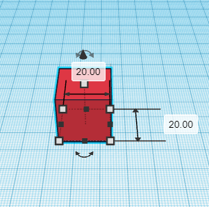
Select the red cube tool and drag it onto the workplane to start the design process.
Several boxes and arrows will show after the cube is on the workplane, allowing us to adjust the shape's size and orientation. You are welcome to click and drag the boxes to experiment with the cylinders' height and width.
Small white boxes with values will appear next to the top and bottom box selections surrounding the shape. These boxes allow users to enter the precise measurements needed based on requirement or preference. This is useful when modelling for 3D printing because it is frequently essential to construct an object within certain parameters.
Lifting Shapes
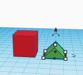
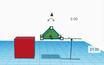
Drag a green roof across to the workplane after that. This form will be the house's roof and will rest on top of our cube.
We must raise the shape off the workplane in order to include it into our design in this manner. Click and hold the black arrow that is hovering above the shape to accomplish that. Once this arrow is clicked, slide the cursor upward and the shape will start to rise.
For example, if the roof is adjacent to the box, a visual marker will show next to the box informing users that the roof is at the height of the box. Tinkercad offers a variety of incredibly useful visual cues and indicators for alignment.
Aligning Objects
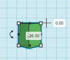
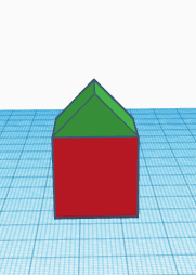
The roof must now be placed atop the box to form a small house.
Drag the shape over the top of the cylinder by clicking it, being careful to keep boxes out of the way. To switch the workplane perspective to an overhead view, use your mouse. In this manner, it is possible to see if the roof has the box's top covered.
Drag the two shapes using the left button on their mouse or trackpad. Make sure both forms are inside the dotted rectangle that appears after the cursor has been selected. Both items will be chosen when the pointer is released, and six black dots should appear; these allow for the left, center, and right alignment of BOTH shapes.
Finalizing the Model
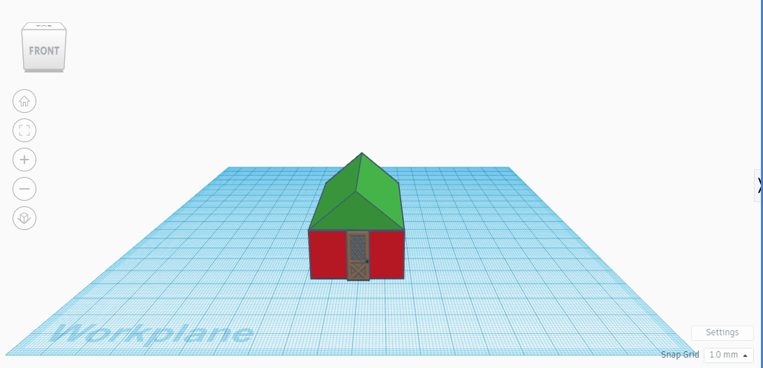
Simply adjust your viewpoint so that you can see your house properly from the side. Add few doors and windows as you wish to make the project more lively. Click the down arrow to lower the roof until it is level with the rectangle. Go ahead and print your new 3D model after clicking the save button!
And Boo Yeahhh! we just made our first 3D model with Tinkercad! Click on the I Made It button below to share your amazing work with the community.