Battery Powered Simple Waste Auditing Data Logger ♻️
by OwenY1 in Circuits > Microcontrollers
2957 Views, 15 Favorites, 0 Comments
Battery Powered Simple Waste Auditing Data Logger ♻️
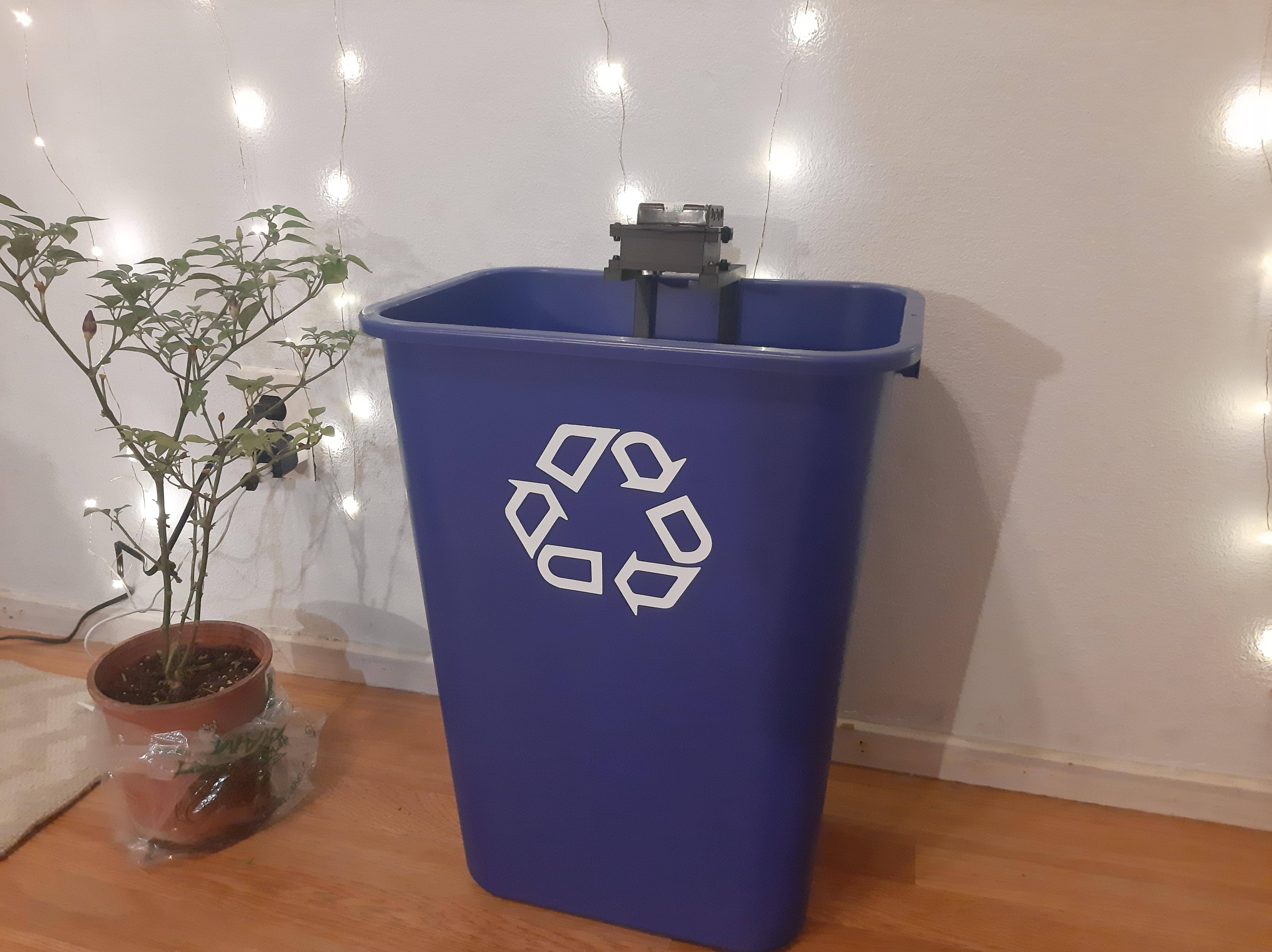
I wanted a way to keep track of how much waste I was generating just to be more environmentally conscious. So I created this project as an automated way to help keep track of waste accumulation through fullness measurements while also taking pictures of the objects thrown away.
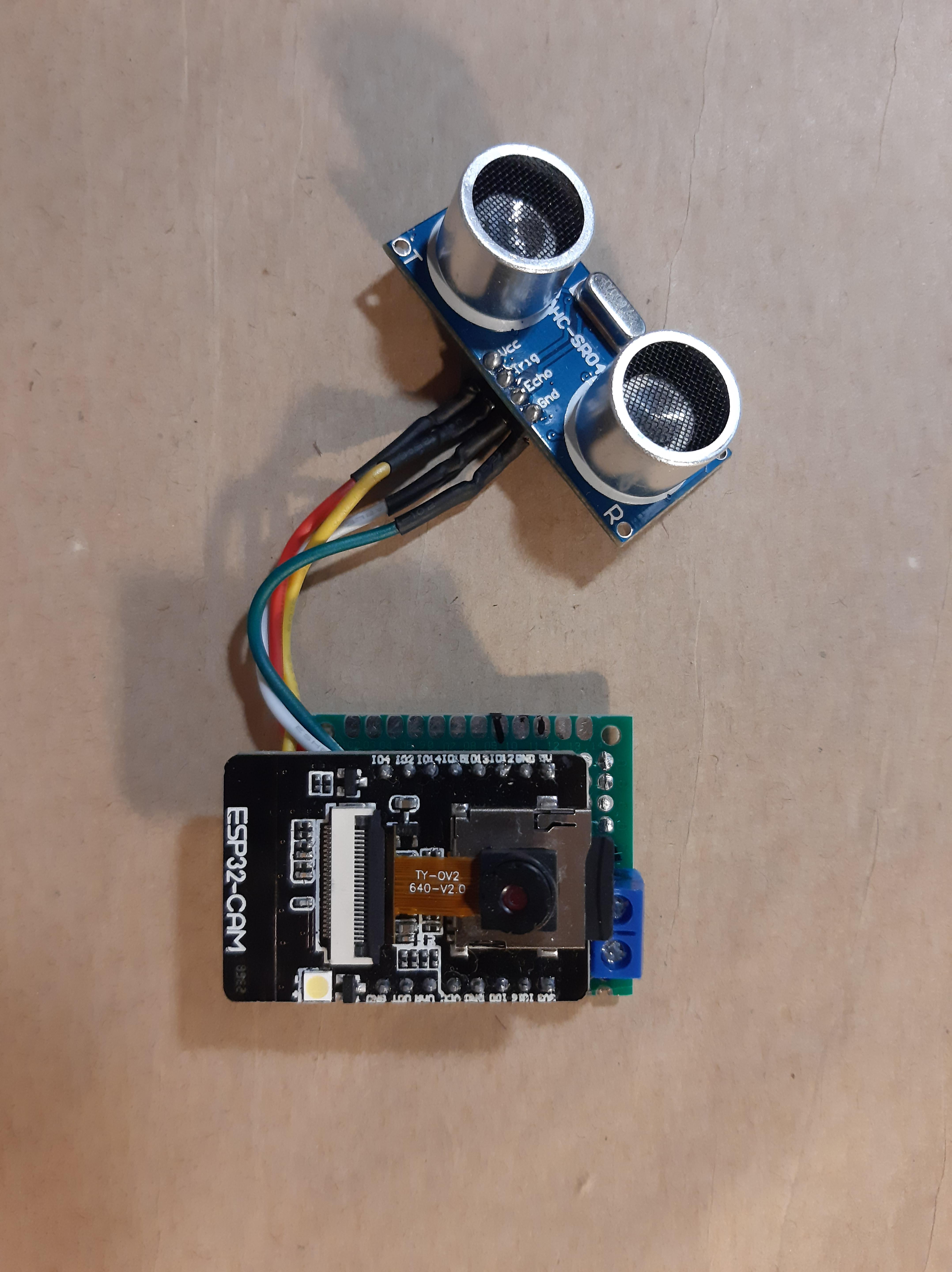
To achieve this, I use the HC-SR04 ultrasonic sensor along with the ESP32-CAM. Doing this type of waste tracking is called a waste audit, which is a common practice used by universities to keep track of waste goals while also looking for opportunities increasing waste diversion rates.
I've actually done a couple in-person waste audits before at my University, it was actually pretty fun and insightful. With this concept I was also able to deploy sensors on 9 bins on campus with a research group called ZotBins. These types of devices helped provide useful insights such as bin usage and fullness trends. I hope to use this project to find my own insights about my own waste stream. This device could have a lot of potential as an IoT device, see the Further Discussion Section below for more details about this.
Supplies 🔨🔧
.png)
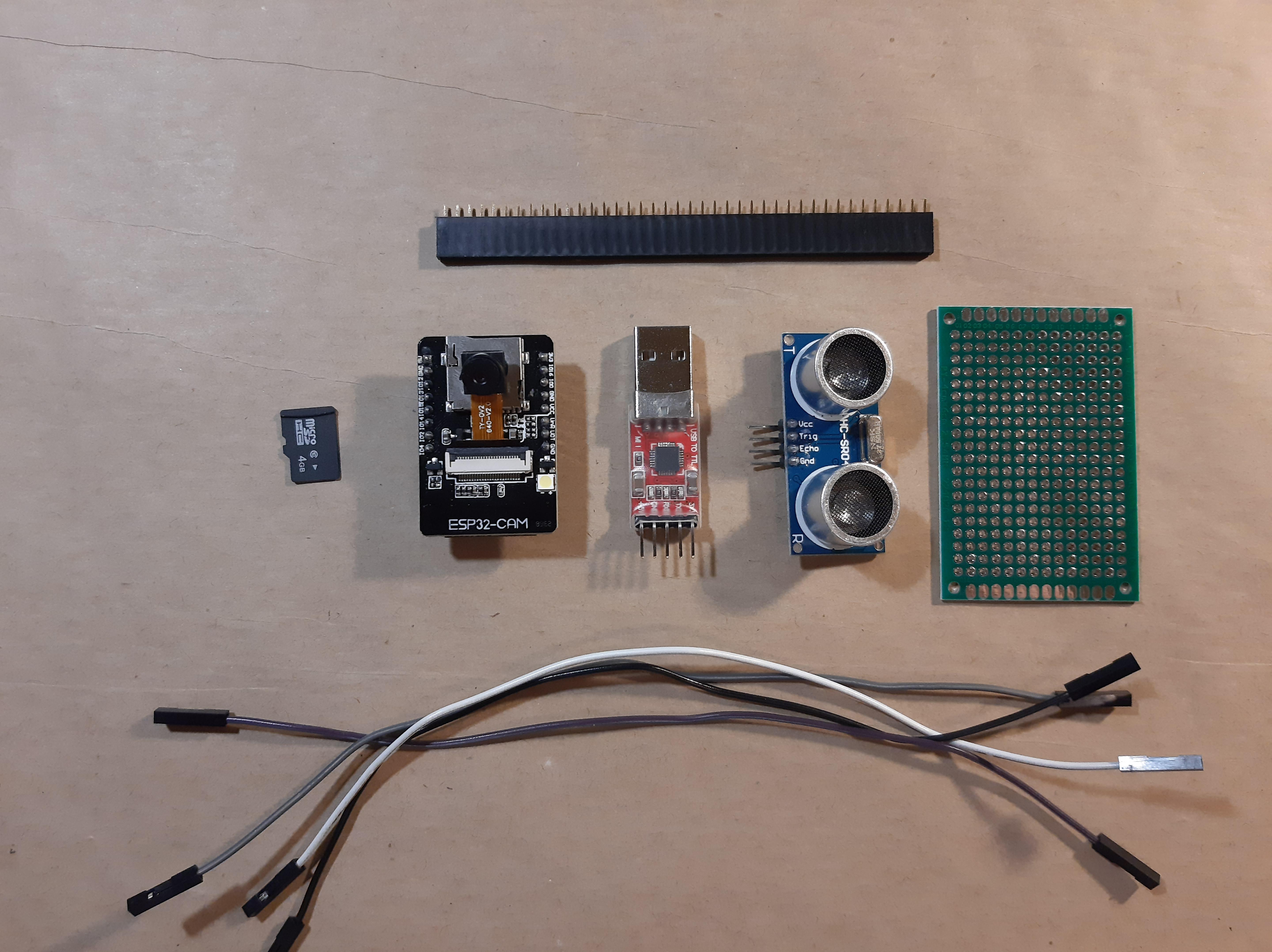
Materials Needed
- ESP32-CAM (~$9 per unit)
- 2 or 4GB micro SD card(~$3.60 per unit)
- 5V Boost Converter (~$1.5)
- HC-SR04 (~$1.60 per unit)
- Solid Wire
- Prototyping Board (~$0.80 per unit)
- Female Header Pins
- Solder
- PLA Filament
- 3 AA Rechargeable Batteries* (~$4.50 per set of 3)
- 3 AA Battery Case (~$0.76 per unit)
- M3 Screws**
*Let's be sustainable and use rechargeable ones :)
**8 mm screws are sufficient, but if you want two bolt the end of the screw you need at least a 12 mm screw (see 3D Printing the Case for a better idea of where the screws will go)
Tools Needed
- Soldering Iron
- 3D Printer
- Wire Strippers
- Computer with Arduino IDE Installed
- FT232RL FTDI USB to TTL Serial Adapter Module (~$3.50 per unit)
-
4 Female to Female Jumper Wires (link above comes with female to female jumper wires)
A lot of the materials and tools I linked could be found cheaper prices if bought from other vendors such as Ali Express or Banggood.
Solder Components on Prototyping Board 🔥
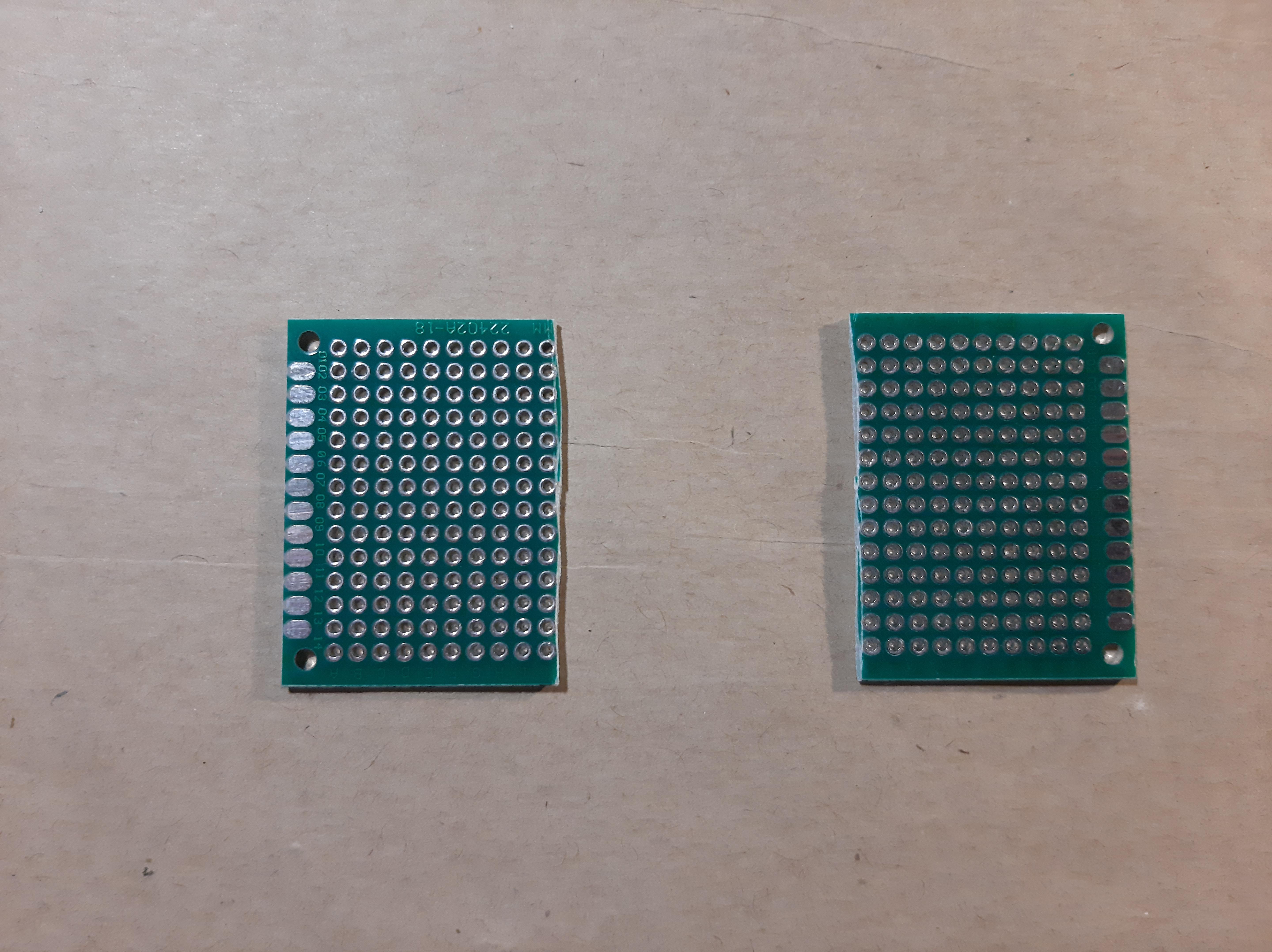
- Use a 4cm x 3cm prototyping board. This will be approximately the same size as the ESP32 CAM. I cut a 4cm x 6cm board in half to get that size.
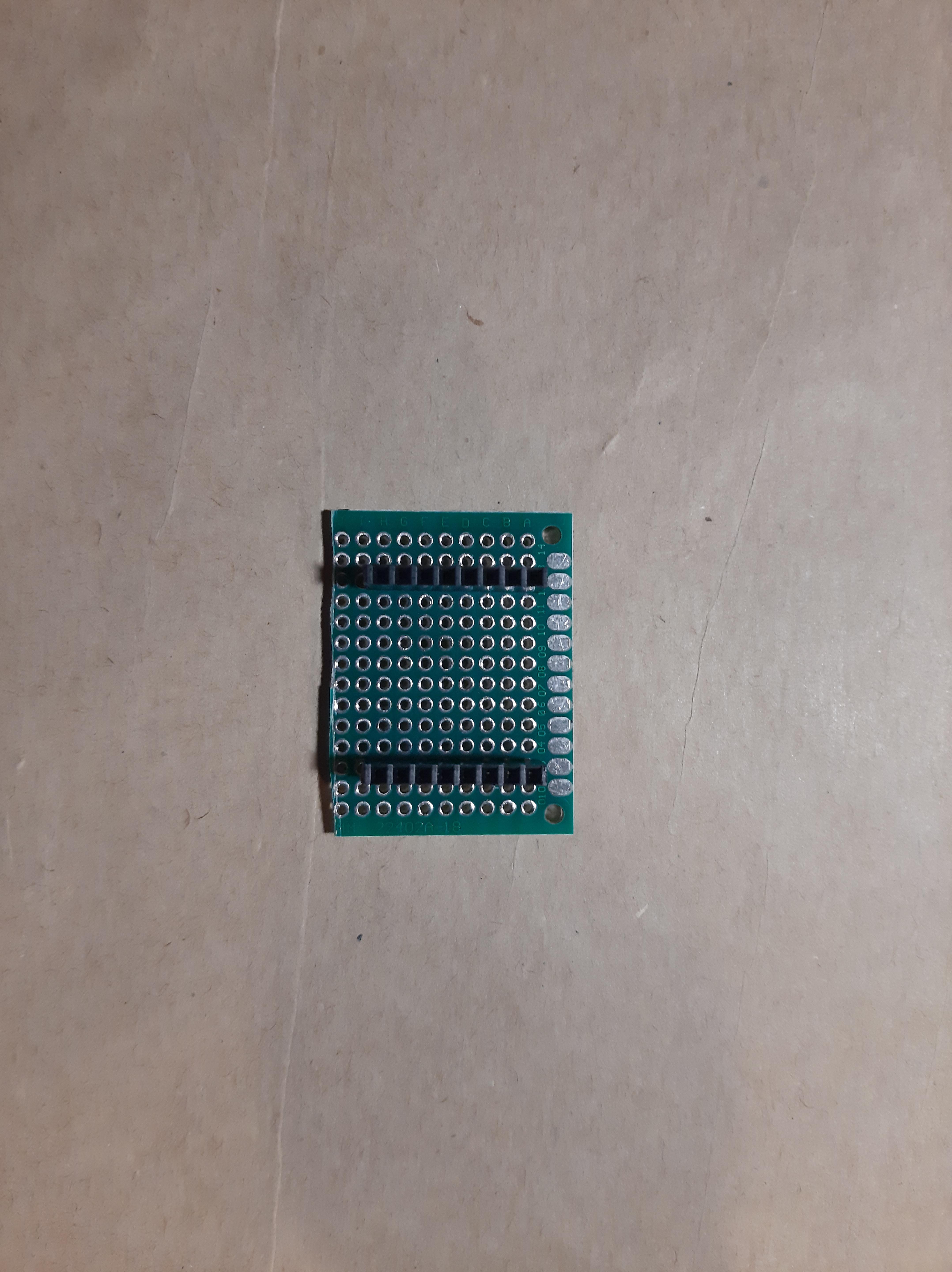
- Use two 8-pin female headers and place it on the center of board for the ESP32-CAM. I just cut a 20 pin female header piece to get the 8-pin female headers.
- (Optional) Place a 2-pin screw terminal block connector near the top. You can use this to conveniently plug in my battery pack of 3 AA batteries. If you don't follow this step just solder the wires from your battery pack directly into the prototyping board.
- Solder wires for HC-SR04 and the 5V Boost Converter. These wires will be used to connect the components to the prototyping board.
- Solder Components. Once everything is placed, just solder those components in place. See image above of my setup for reference.
- Plug in your ESP32 CAM into the female headers for reference. Helps you see which pins for the female headers correspond to which pin on the ESP32 CAM.
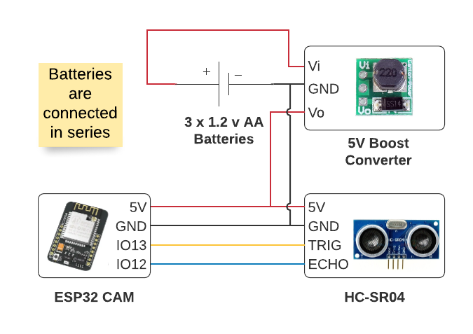
- Solder connections according to wiring diagram above.
Circuit Explanation
I decided to use the female headers because I wanted to reuse my ESP32-CAM for other projects as well. If you don't mind, you can directly solder everything on the ESP32-CAM.
Power Analysis ⚡
Current Draw Values
ESP32-CAM Active Mode 1 = 60-260 mA
ESP32-CAM Deep Sleep = 10uA
HC-SR04 Working Current = 15 mA
Explanation
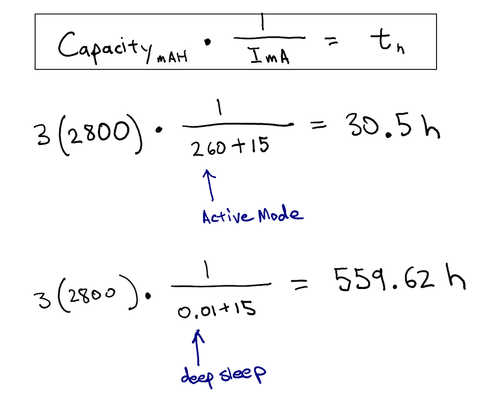
With the values above I settled on using three 2,800 mAh capacity rechargeable AA batteries. I determined this by doing some quick calculations. I first did a high power consumption calculation where the ESP32-CAM is always in active mode, the battery lasted only 30.5 hours. Then I did a low power consumption calculation where the ESP32-CAM was always in deep sleep, the battery lasted 559.62 hours. I know that my code is in deep sleep most of the time so my estimates on how long this will power the sensor module will probably just be a couple hours less than 559.62 hours. So definitely enough to power the project for at least a week!
Download the Arduino IDE and Add ESP32 Package ⬇️
)
I was going to write my own instructions for this, but mine was really just going to be a derivative of the one on Random Nerd Tutorials. Their content is really amazing and informative so big thank you and acknowledgement to the blog creators Sara and Rui for making these resource available to the public. So instead, please follow the instructions by watching their video or by following their tutorial, but please stop once you have the Arduino IDE and the ESP32 by Espressif Systems package installed. I will give specific instructions for setting up the ESP32 CAM that varies from the tutorials in the next step.
Video Tutorial: Install the ESP32 Board in Arduino IDE in less than 1 minute (Windows, Mac OS X, and Linux)
Written Tutorial: Installing the ESP32 Board in Arduino IDE (Mac OS X and Linux instructions)
By the end of this tutorial you should have the following:
- An Arduino IDE
- The correct esp32 library added in the Preferences from this source: https://dl.espressif.com/dl/package_esp32_index.json
- esp32 library by Espressif Systems installed from Tools > Board > Boards Manager
Select AI Thinker ESP32-CAM As Board in Arduino IDE ✅
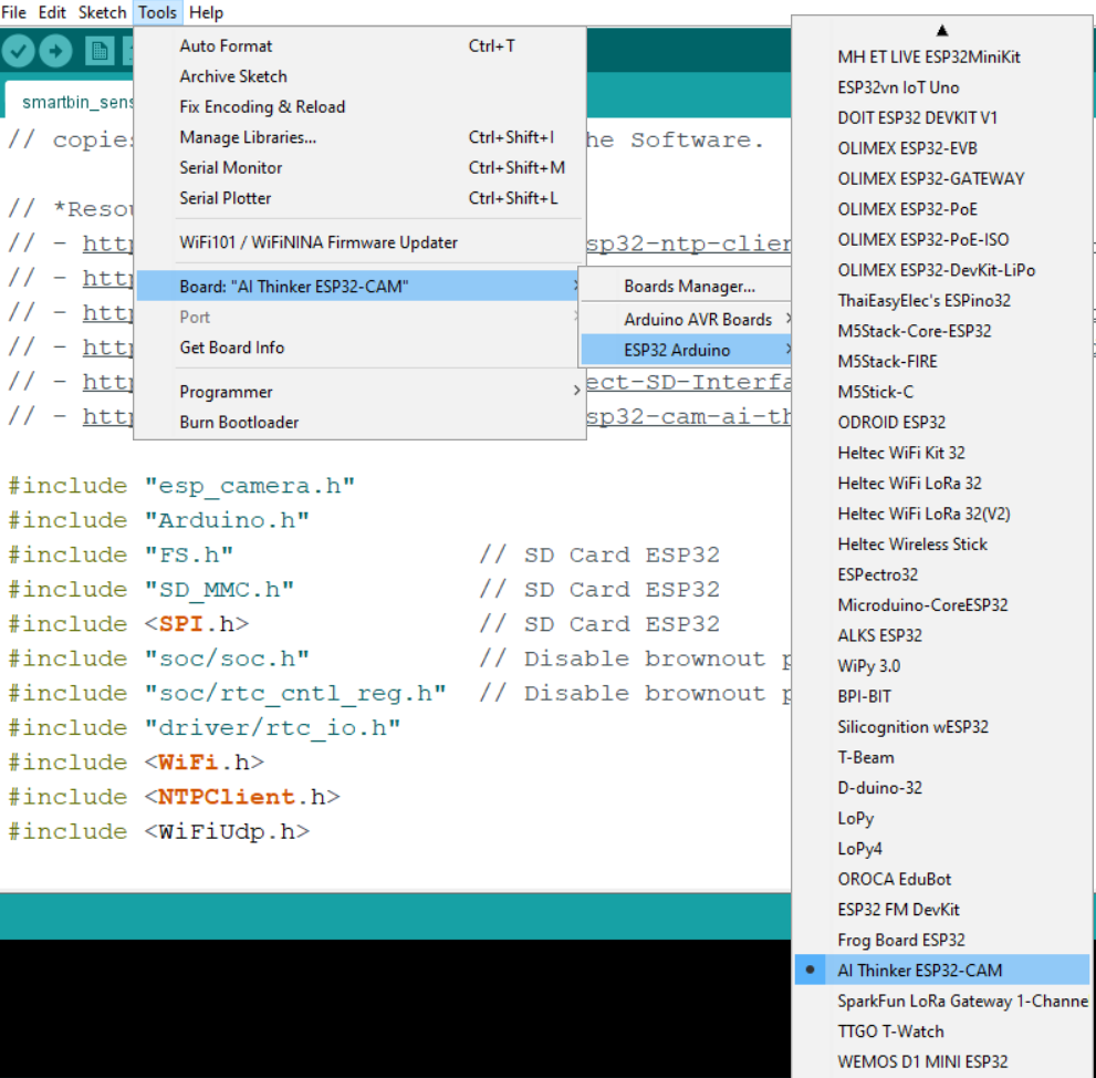
Refer to picture above for reference.
- Near the top left of the Arduino IDE select Tools
- Then go to Board > ESP32 Arduino > AI Thinker ESP32-CAM
- You might have to scroll down a bit to select AI Thinker ESP32-CAM
Installing the NTP Client Library 🕙
We'll be using Wifi and connecting to a NTP server to keep automatically determine the date-time stamp of when the fullness data was collected and when the image was taken. The NTP server is in UTC time, you can add offsets in the code to match your timezone, I explain this in the Code Explanation section.
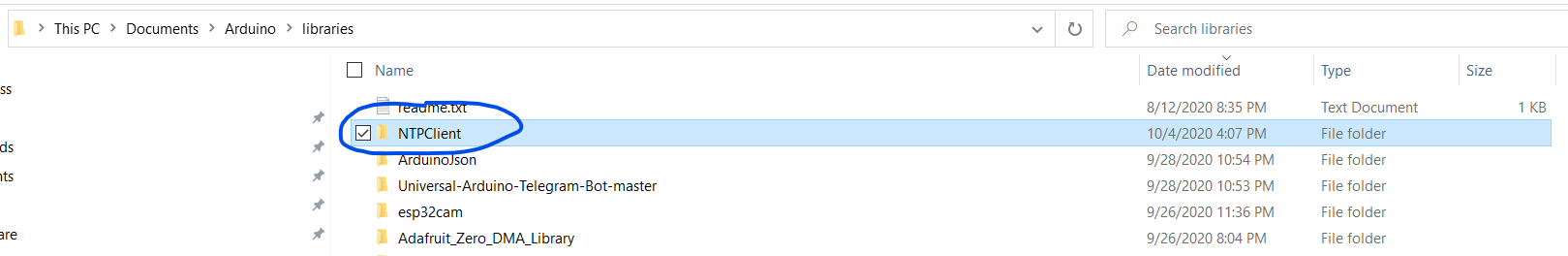
- Download the NTP Client Library from GitHub here: https://github.com/taranais/NTPClient/archive/master.zip
- Unzip the file and go into the folder. Rename the folder NTPClient-master to NTPClient
- Move the folder to your Arduino IDE installation libraries folder. On Windows, I move the folder here: C:\Users\REPLACE_WITH_YOUR_USERNAME\Documents\Arduino\libraries
- Restart the Arduino IDE
Preparing to Upload Code to the ESP32 CAM ⬆️
Now that you have all the software setup. Let's start with programming the ESP32-CAM.
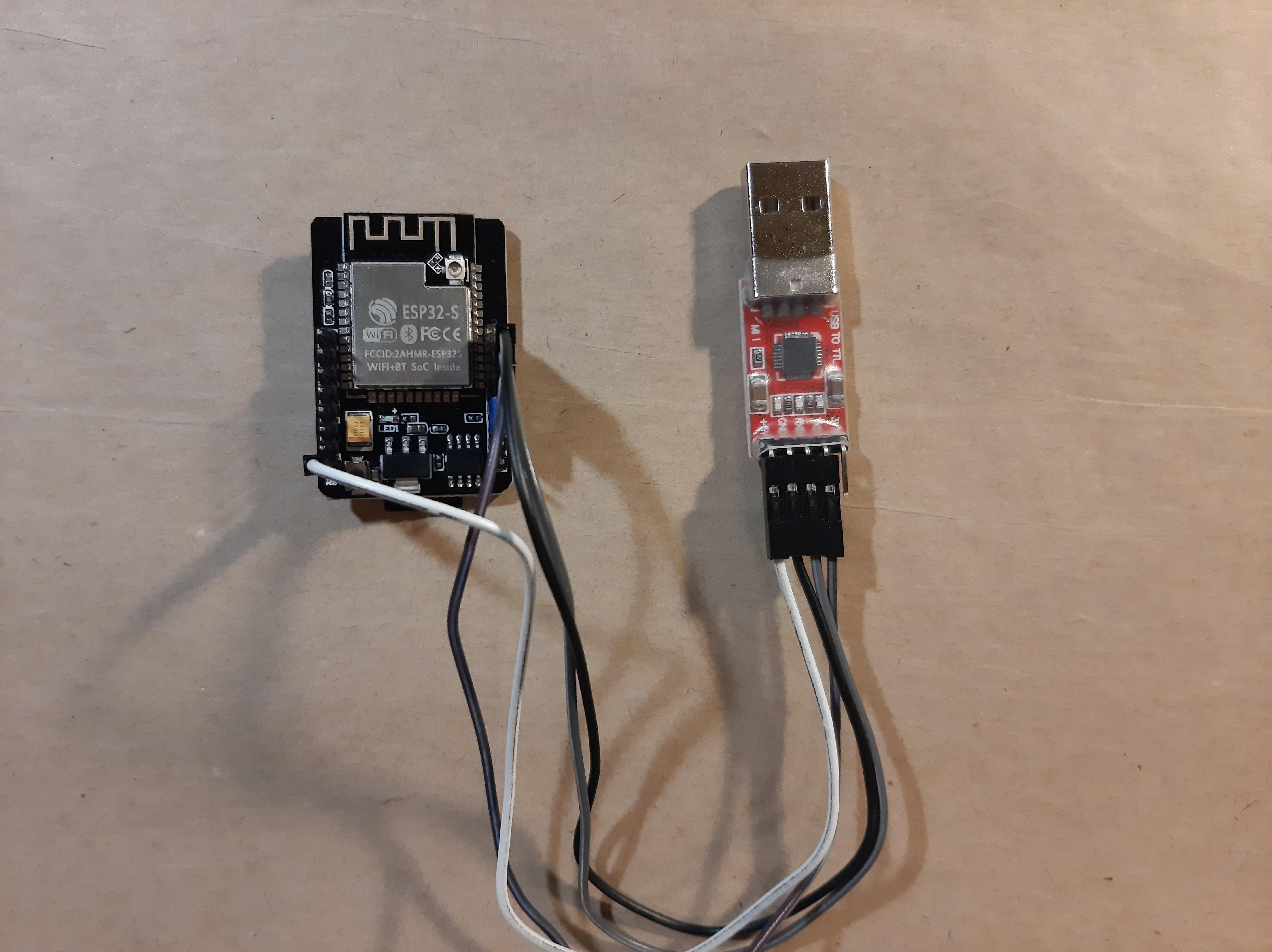
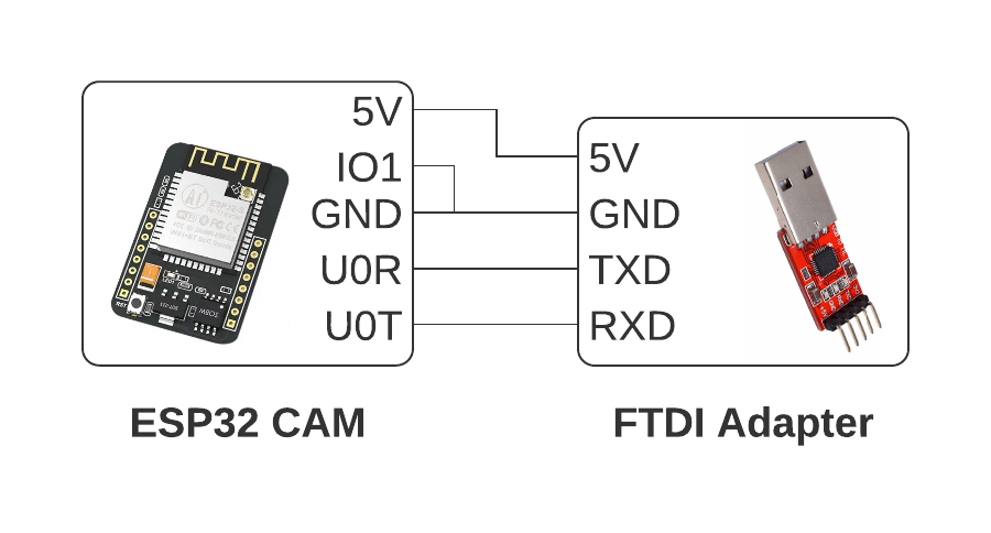
- Get your FT232RL FTDI USB to TTL Serial Adapter Module (FTDI Adapter) and your Female to Female Jumper Wires
- Connect the FTDI Adapter pins to your ESP32-CAM according to the diagram above
- Plug in your FTDI Adapter USB side to the computer and make sure that your computer is able to recognize the device. If your computer does not recognize the device follow these steps:
- Locate the required drivers here: https://www.ftdichip.com/Drivers/D2XX.htm
- Scroll down to the table and locate the driver for your operating system and follow the instructions
- If you have a Windows machine scroll down to the table and locate the first row and click on the hyperlink labeled as Available as a setup executable
- Once downloaded, run the executable as Administrator
- Now, we are going put the ESP-32 CAM in programming mode
- Make sure to connect the IO0 pin to the GND pin using either a female to female jumper wire or a jumper cap.
- Press the reset push button on the back of the ESP32-CAM and now you should be in programming mode. This will allow you to upload your Arduino Code
Modify and Upload Code to the ESP32-CAM 💻
Now, we're going to download the code and make some changes so that everything will work. Make sure you are still in programming mode (explained in previous step) and that your FTDI Adapter device is connected.
- Download the code attached in this step or from GitHub: https://github.com/zotbins/simple_waste_data_logger
- Open up the code in the Arduino IDE
- In the Arduino IDE, make sure you select the port your FTDI Adapter device is on. Tools > Port
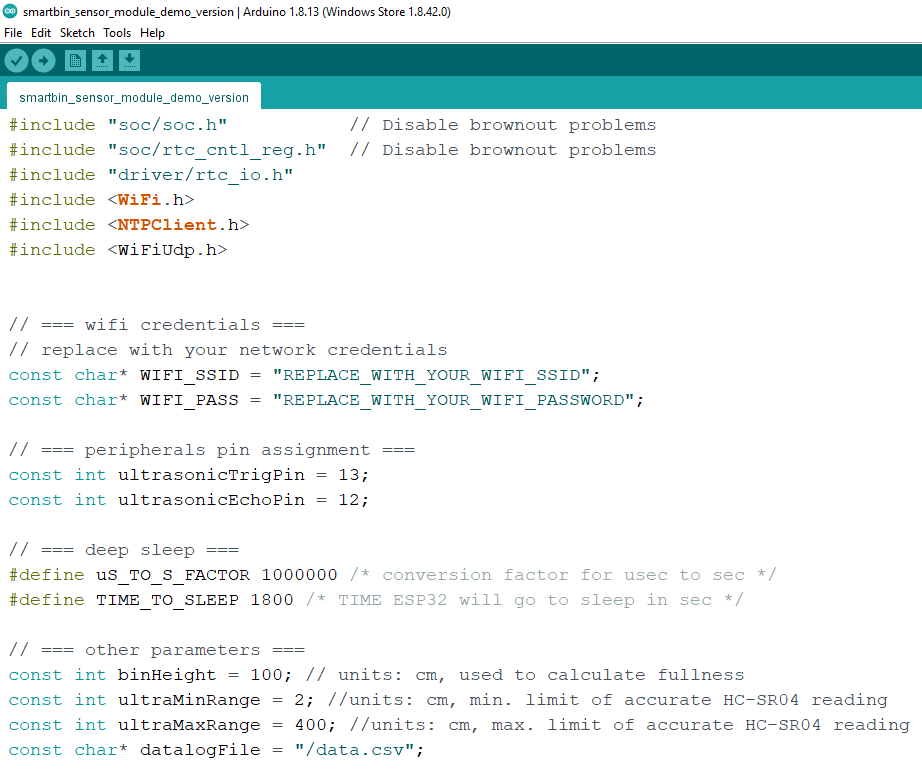
- Change the following variables to match your WiFi Network
// === peripherals pin assignment ===

const char* WIFI_SSID = "REPLACE_WITH_YOUR_WIFI_SSID";

const char* WIFI_PASS = "REPLACE_WITH_YOUR_WIFI_PASSWORD";
- Measure the height of your bin and change binHeight value to reflect the height of your particular bin
const int binHeight = 100; // units: cm, used to calculate fullness
- Now, compile and upload!
- To test if the code works, you can open the Serial Monitor on the Arduino IDE, unplug the connection from the IO0 pin and the GND pin, and reset the ESP32-CAM. This should get the ESP32-CAM out of the programming mode and will run the code we compiled and uploaded.
Code Explanation 💬
Feel free to skip this section if you are not interested or just save it for later.
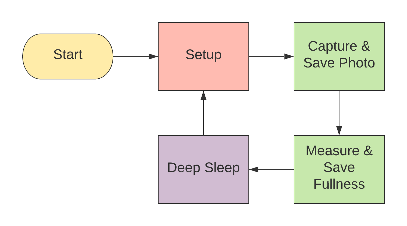
Above, is a quick high-level flow chart that shows the logic of the code. It is pretty simple.
However, if you want a more in-depth explanation, I made a PDF document and made it accessible on GitHub. The code explanation document will go through each block of code and also have some high-level explanation. Please see the code explanation at https://github.com/zotbins/simple_waste_data_logger/blob/main/code_explanation.pdf. You can download the PDF and view it in a PDF reader of your choice.
Format and Install Your MicroSD Card 💾
- Insert microsd card into your computer
- Format the SD card to a FAT32 file system
- Once formatted, insert it into your ESP32-CAM
3D Printing the Case 🔧
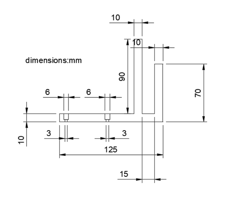

- Download the the STL files from https://github.com/zotbins/simple_waste_data_logger/tree/main/stl_files
- Set infill to 10% and use supports
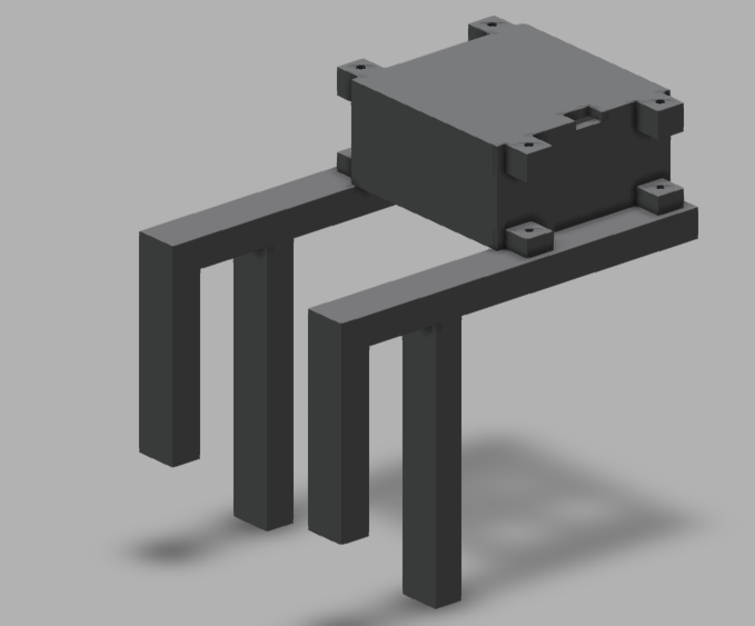
- Print two of the sensor_mod_handle.stl
- Print one of the sensor_mod_top_assembly.stl
- Print one of the sensor_mod_bottom_assembly.stl
Currently, this design only fits on a bin with a 1cm width lip. You may have to modify the CAD file. I have included a Fusion360 file called sensor_mod_handle v9.f3d that you can modify to fit your needs. Another option is to design your own handles for your bin, I made the case pretty modular where you can create a custom attachment with M3 screws. In the future, I plan to create a more flexible design.
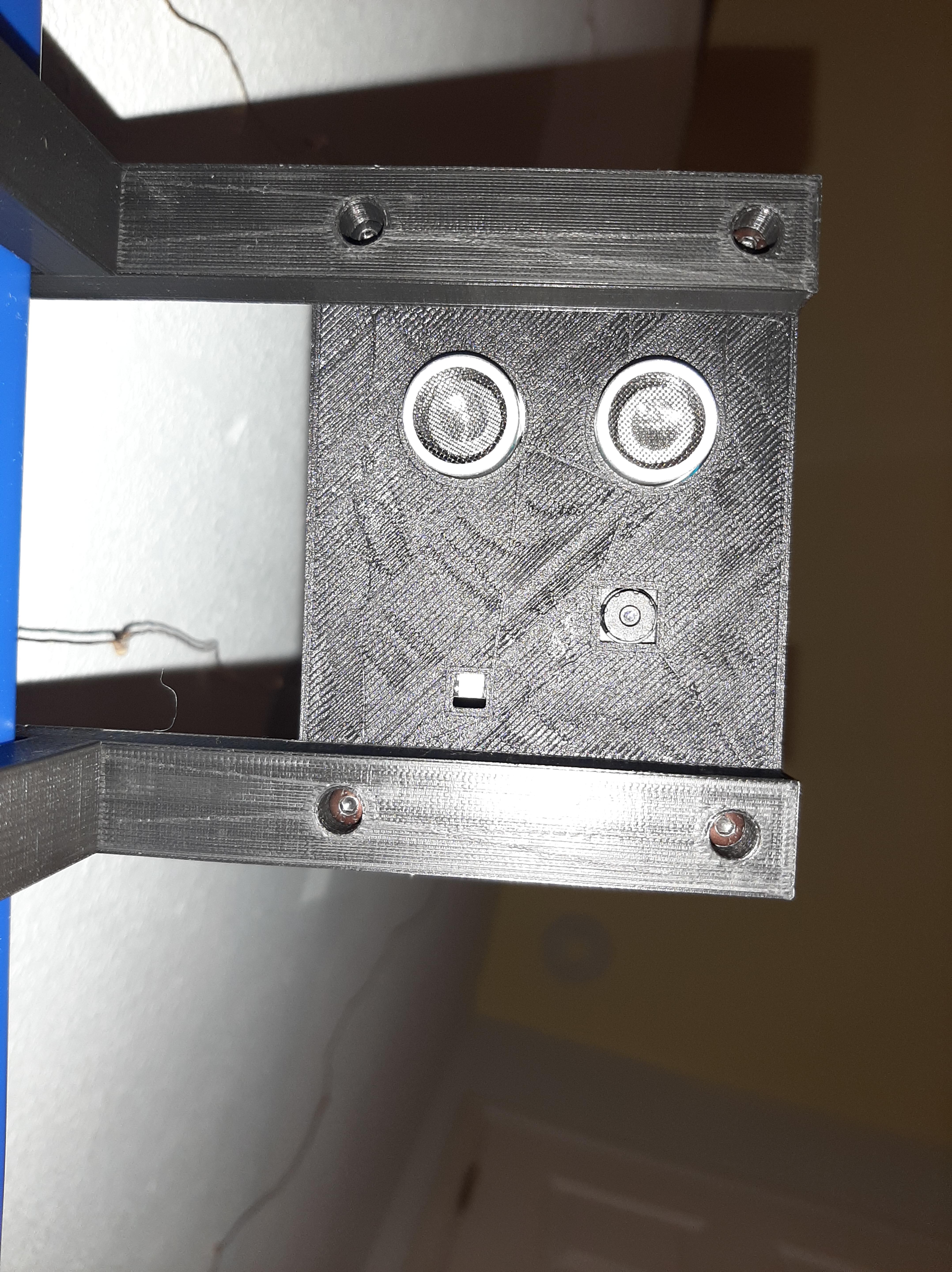
Start Data Logging 📊
By this step, you should have uploaded the code to the ESP32-CAM with the microSD card inserted, have a prototyping board with the soldered circuit (HC-SR04, Female Headers, Battery Pack Holder) on it, and have a enclosure for all the components.
- Plug in ESP32-CAM into your prototyping board
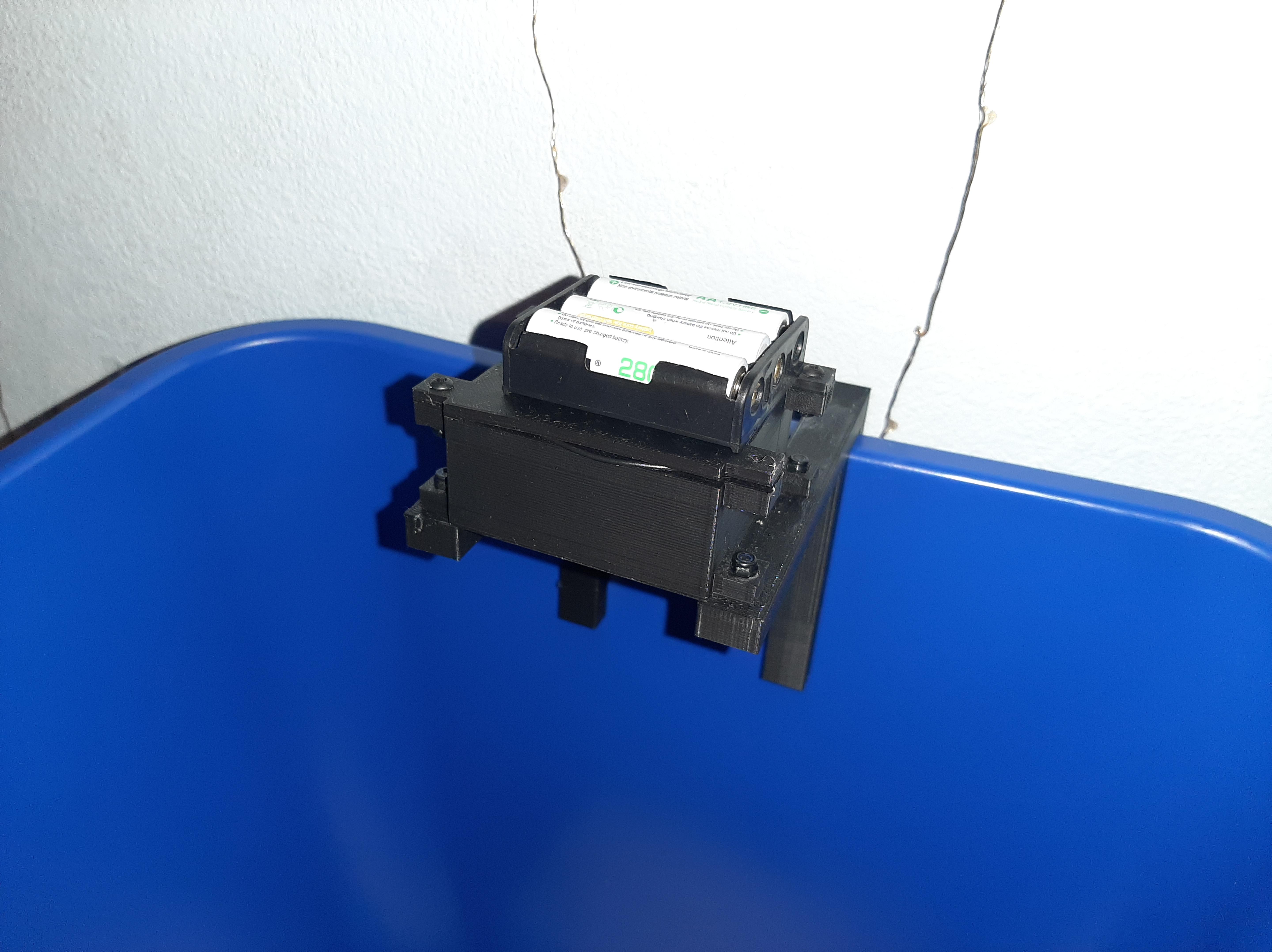
- Put the assembled board into your 3D printed enclosure
- Attach the enclosure onto a waste bin
- Power your module by adding 3 AA batteries into the battery holder attached to the boost converter 5V and GND
- Congratulations! The code should start running and logging data!
- After a period of time, you can go ahead and unplug the SD card and look at what you've thrown a way and also see the fullness trend over time. It's definitely more meaningful to collect data over a long period of time than a short period.
Debugging
- The flash on the camera should flash really brightly once and then go into deep sleep.
- If it keeps on flashing a couple times repeatedly every few seconds or so that means that the ESP32-CAM failed to connect to the camera module. Try resetting the board
- More debugging tips to come as I use this more and as I receive more feedback
Further Discussion 💬
Possible Improvements
- The flash LED of my ESP32-CAM would still be on during deep sleep. Maybe after some more in-depth debugging I can figure out how it should be off and decrease the power consumption.
- Turn on red led on the back of the ESP32 board to indicate possible errors
- Add a photo resistor to detect light conditions and determine when to activate the flash
- Add a NPN transistor to turn on and off the HC-SR04 when needed
Future Work
- Log data to a HTTP server instead of micro SD card. This will free up a lot of IO pins to add more sensors
- Add a load cell to collect the weight of the trash. This is a useful measurement for waste auditing rather than just using fullness
- Possible outdoor deployment setup with solar panel
Expanding This Project
At UCI, I helped lead an undergraduate research group called ZotBins where my team actually deployed smart bins that collect waste related data (eg. weight, bin fullness, bin usage, images, etc.) in various locations such as food courts and office buildings where we had over thousands of users using our bins. Some bins were also interactive as well through the use of digital displays! I think there are many possibilities with this type of technology that includes but is not limited to:
- Optimizing waste pick-up for waste management through the use of real-time fullness data.
- Comprehensive waste stream analysis through various types of data mentioned above so waste management and manufacturers can create better strategies for encouraging more recycling, composting, and better sorting of trash to reduce contamination.
- Bringing awareness to the the amount of waste people generate and educate them with concrete data on how they can improve their waste-related habits.
Now, I'm exploring creating an open source version of ZotBins so that any city, business or university campus, retail center, classroom, home, and more, can deploy these sensors and have a suite of applications to better inform all actors in the municipal solid waste stream system and help close the loop for a sustainable society. If you are interested in learning more you can visit my blog at https://zotbins.github.io/zbceblog! I'm just getting started with this endeavor so I definitely would appreciate any feedback.