Basys Board Binary Count-To Game
by Gerome1343 in Circuits > Microcontrollers
1745 Views, 1 Favorites, 0 Comments
Basys Board Binary Count-To Game
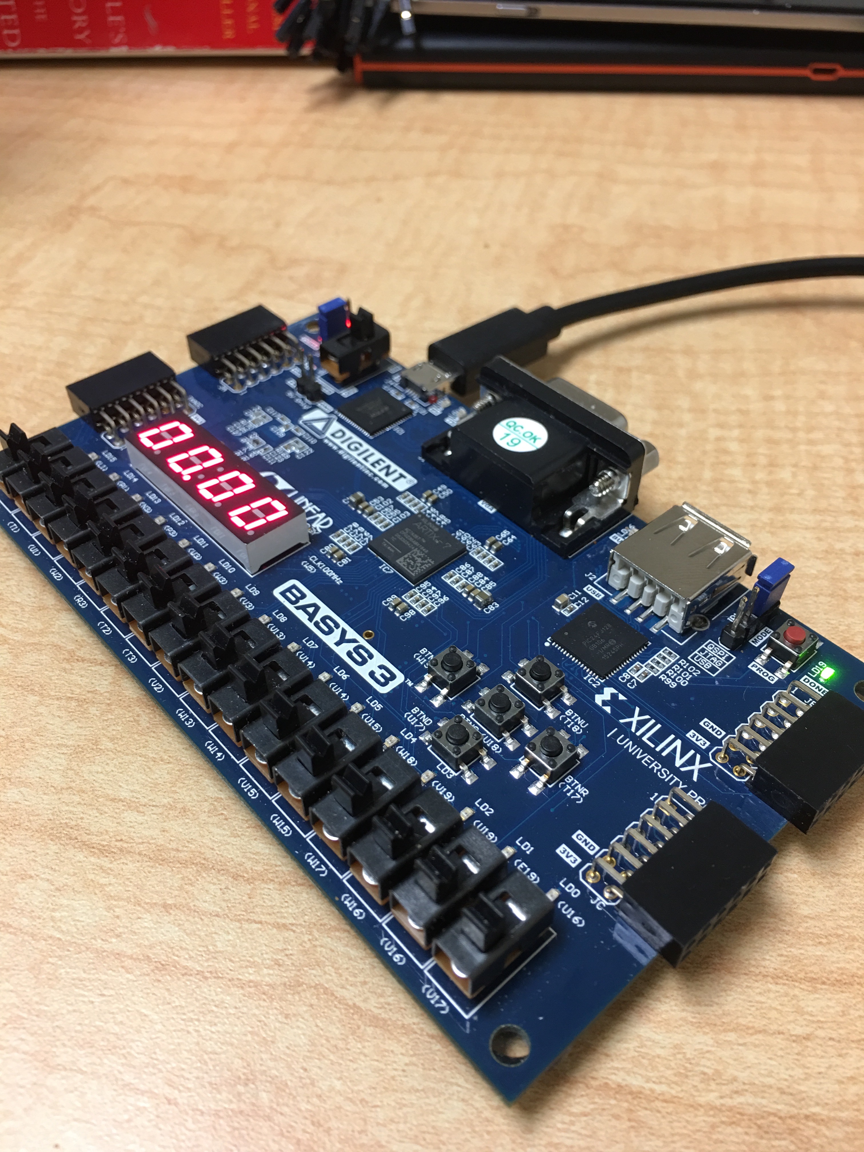
This instructable tutorial show you how to construct a game that times a player's ability to count from 0 to 15 in binary using the switches on the Digilent Basys 3 Board. While a player is switching through the numbers, the row of LED's on the Basys 3 board will light up to display the number that the player is currently on. The time is to be displayed on the board’s seven segment display and will go from 0.00 seconds to 99.99 seconds. If a player is to run out of time, the LED's will display a losing state.
To use this code, you will need:
- A Digilent Basys 3 FPGA Board
- Computer with the Xilinx Vivado Software (Webpack Edition will work). For this module, we used the 2017.2 version.
- A Micro USB Cord (Data transfer capable)
Authors:
Gerome Cacho, EE Major, Cal Poly SLO
Jose Hurtado, EE Major, Cal Poly SLO
Class:
Digital Design - EE/CPE 133
Instructor:
Paul Hummel
Step 1: How It Works
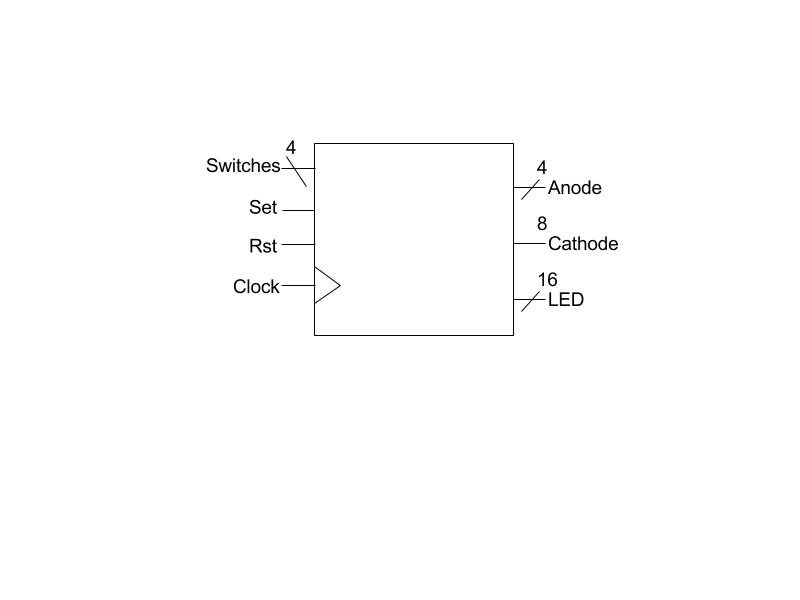
Inputs: The module utilizes the 4 right-most switches on the Basys board. It also makes use of the middle and left push buttons located near the middle of the board, as well as the built-in 100 MHz clock.
Outputs: The module utilizes the 4-digit 7-segment display on the Basys board, which internally consists of 4 Anodes controlling each digit, which are all connected through common cathodes referring to the segments. It also makes use of the LED’s of the Basys board located near the bottom of the board, above the switches.
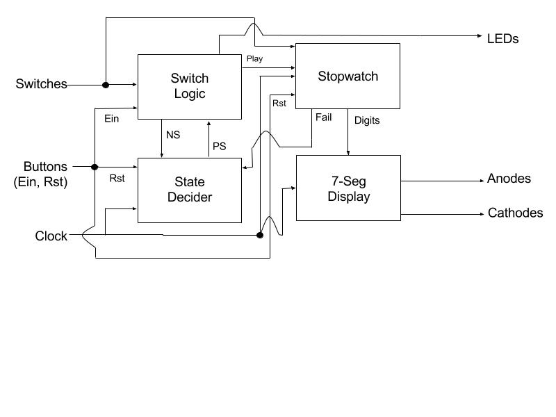
Within the program, there are multiple “sub-modules” that are functionally different from each other yet contribute to the entire code as a whole, in the form of process blocks:
Switch Logic: This process block controls the switch logic for module. This works in large cooperation with the state decider process block. The way this block is designed, the switches move the user through multiple unique states states until being transferred into the “winning” state. This process block also controls the row of LED’s that light up as the player is going through the different states. Once the game has been initialized, the LED light up accordingly so the user will know what number he/she has to count to next, up until all LED's are displayed.
State Decider: This process block indicates the number state that the player is in as they are going through the sequential number combinations in the switches. As the player goes through the different states via the Switch Logic process block, a new LED will light up until they reach the final one, where the clock stops and a win state is displayed. Alternatively, if the player runs out of time, then a fail state is displayed.
Stopwatch: This process block controls the digits being displayed on the seven segment display, so that they may cycle through the numbers in order, and increment the following digit once a digit has completed its 0-9 cycle. If the stopwatch reaches its maximum value (in this module, 100 seconds), then it will relay an active "Fail" signal back to the State Decider process block, which will move the state automatically to the Fail State.
Seven Segment: This process block controls the actual LED’s that need to light up as the stopwatch is on, since the LED’s on the seven segment display share a common anode and cathode. Each digit within the 7-Segment is tied to signal within the Stopwatch module, and have specific directives to follow depending on what the digit value is at a moment in time.
Attached is a diagram display the circuit architecture of the module, showing the interconnected relationships between all 4 process blocks.
Step 2: Wiring Up the Board
.jpg)
To wire the board, you can will need to create a constraint file and ensure that the board is wired up to the proper components specified on the board. To do so, you can copy and paste Basys3_Master.xdc file into your constraints file, and use the Basys3_ReferenceManual to ensure that you wire the board to the correct components. In addition, we will be supplying our own constraints file to avoid the hassle.
Step 3: Programming the Basys Board
Once you have completed the setup for the counter game, you can generate the bitstream for the code, which will also run the synthesis and implementation for the board. During this stage, some errors may pop up, so make sure the are resolved before you try to program the board to ensure that the game functions properly. Once the bitstream has been generated, you can open the target for the device and use auto connect function to program the Basys3 board.
Attached is the code for the Count-To-15 game, which has a maximum stopwatch timer of 100 seconds, as well as a tutorial for how to program the board, provided by our professor on the class page.
Step 4: How to Use It
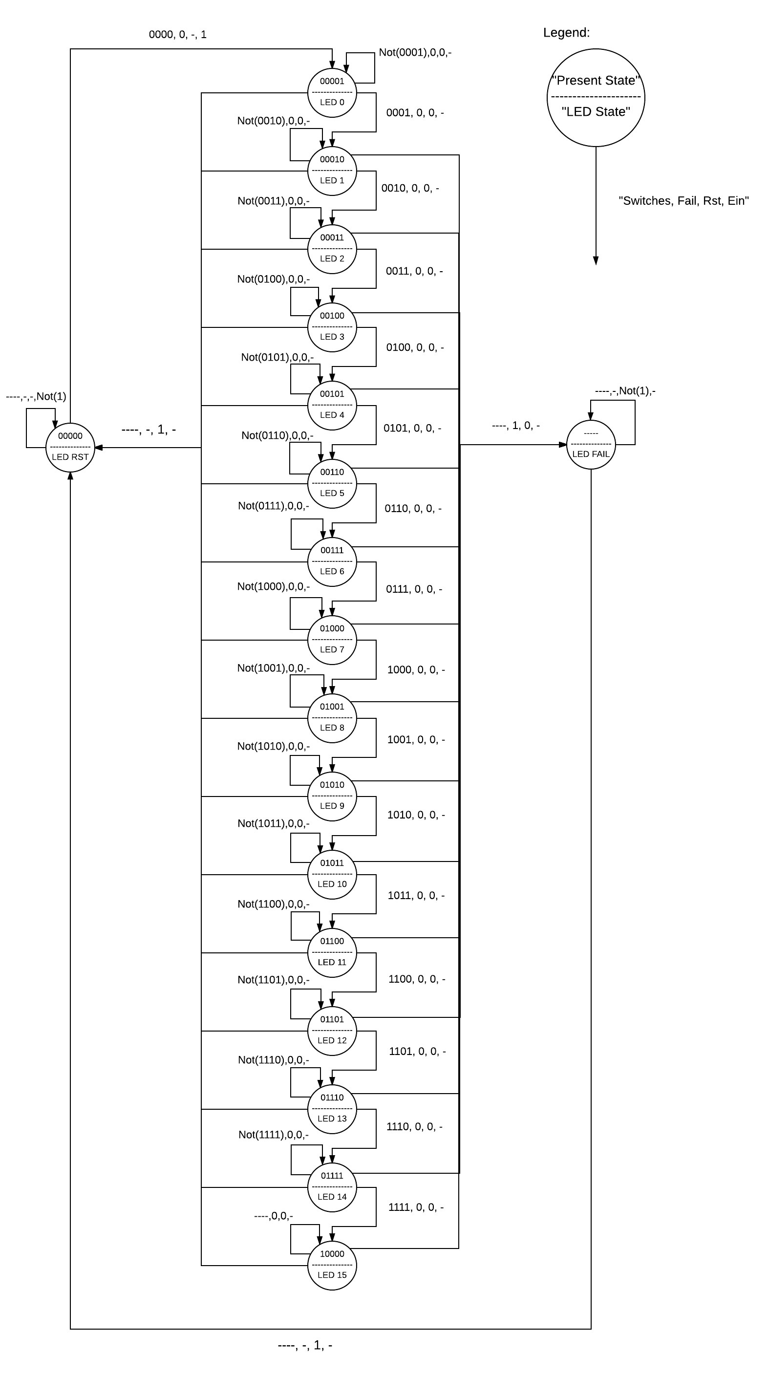
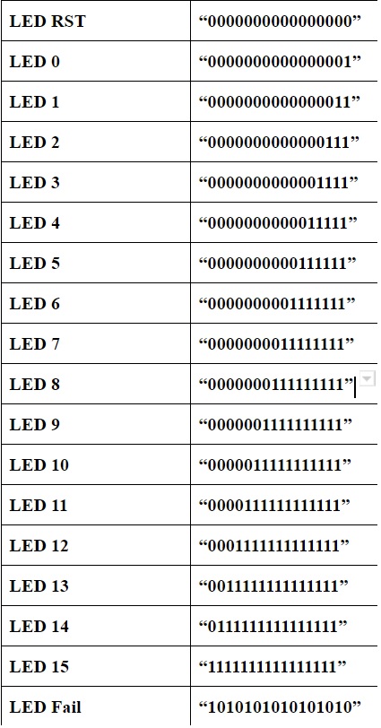

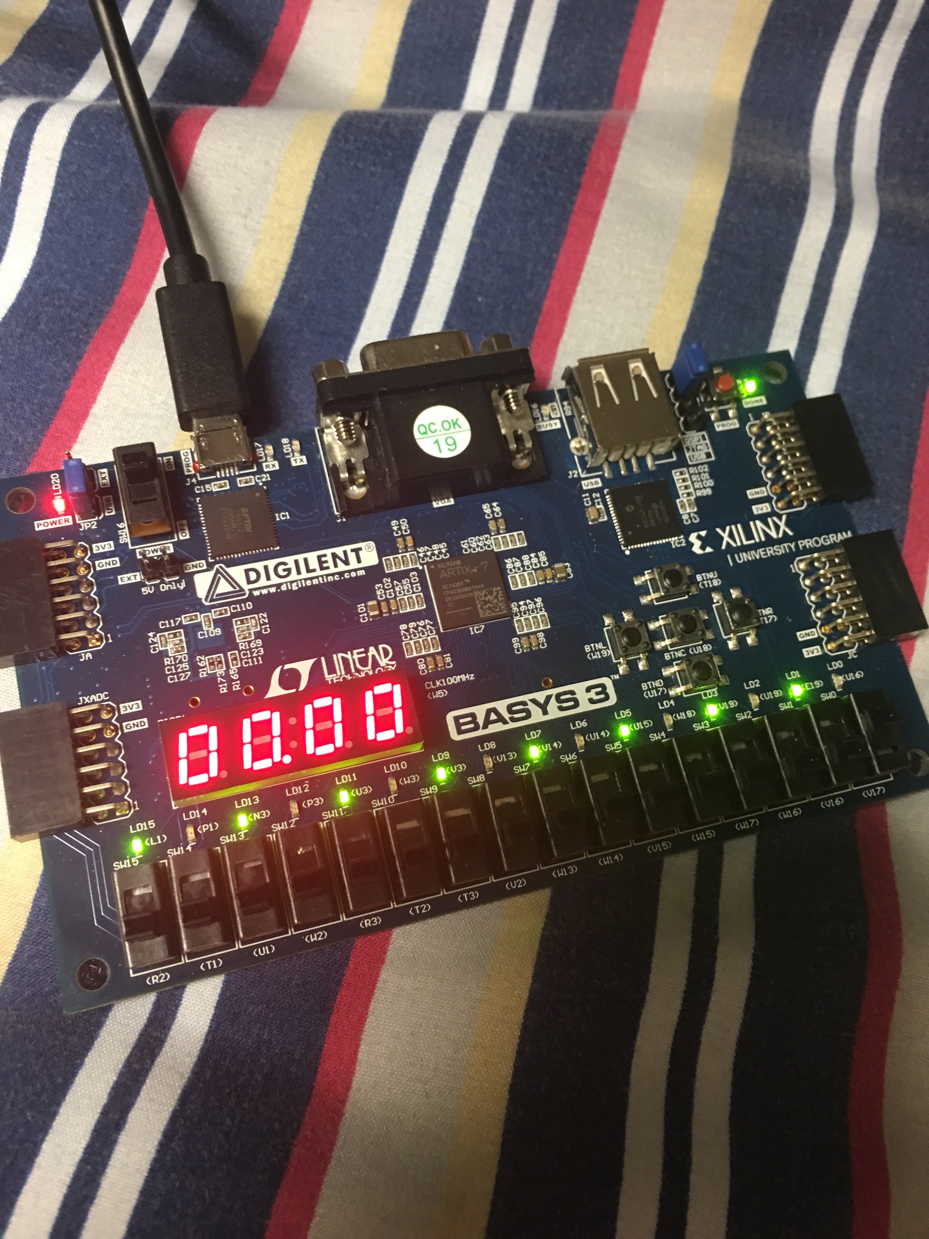
The game can be reset at any point using the reset button programed (BTNC U18 in our code), and this will clear the clock and any LED’s that have been turned on. To put the game in its start position, Switched 0 through 3 must be in the off position, before pressing the set button (BTNC W19 in our code) will work and turn on the LED in the 0th position. Once switch 0 is turned on (LSB), the clock will start, and will continue to run until all progress stages of the game have been completed in order, or until the stopwatch reaches its maximum value, which will sent the user to the “fail” stage of the game.
Attached is the State Diagram of the Switch Logic Process Block, a table of LED lights correlating to the state diagram, a video of the module working, and a picture of the fail state.
(Optional) Step 5: Modifications
Say you want to customize the game, so you can practice your counting to a number other than 15, or want the stopwatch maximum limit to change from 100 seconds. In this step, there is supplemental code provided that will tweak the code. Once you download the document (as a .pdf), go into the program "game" which is the main code, and replace the process blocks in the game with the process blocks in the .pdf with the same name. In addition, if you would like to use the Count-to-31 Module, you need to incorporate a new constraints file as it has an added input. The constraints file is shown here, called "Final Code Constraints". Subsequently, if you would like to use the Count-to-6 Module, you would need to incorporate the appropriate module, which is given here as well, labeled "Final Code 6 Constraints".