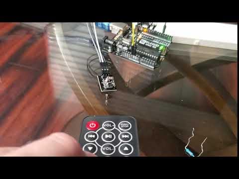
Basic Infrared Receiver Tutorial


This Tutorial is to show you how to set up an Infrared Receiver and map LED to the buttons on the remote.
I have been thinking of a project where I can use a remote to activate a pattern of LED lights, but the first problem is that I had no idea where to start. So I decided to start with something basic.
Supplies
1 UNO R3 Cotroller Board and usb cable -13$
https://www.amazon.com/ELEGOO-Board-ATmega328P-ATM...
1 Breadboard -10$
https://www.amazon.com/Breadboards-Solderless-Brea...
1 Remote control &1 IR Receiver Module- 6$
https://www.amazon.com/KOOBOOK-Infrared-Wireless-C...
3 Female to male Dupont Wires &11 Breadboard Jumper wires - 6$
https://www.amazon.com/EDGELEC-Breadboard-Optional...
3 220k resistors &1 10k resistor - 7$
https://www.amazon.com/Cutequeen-Values-Compliant-...
1 Red LED, 1 Blue LED ,1 Green LED - 6$
https://www.amazon.com/eBoot-Pieces-Emitting-Diode...
Everything found here can be found in the ELEGOO Super Starter Kit UNO R3 Project https://www.amazon.com/ELEGOO-Project-Tutorial-Con... 37$
Most of this stuff is very commonplace, and if you don't have any of it I recommend getting the Super Starter Kit
Step 1: IR Receiver Plug In

Okay so this seems super basic and it is, but it is important to grasp this before using the IR Receiver for your own projects.
There are 3 pins on the IR Receiver
S, VCC, and GND
Here is what they will connect to
S- D4
VCC- 5V
GRN- GND
The S will go into the 4 on the Uno board, VCC will attach to the positive line of the board while GRN will go with the negative.
This resistor is the 10k resistor
Step 2: Connecting the IR Receiver to the UNO


These three images are all different angles of the same step
Two pins under the FtM wire connected to S you will connect to the 4 on the UNO board
Next to that will be the wire connected to the ground or the negative side of the board
Next will be connected to the positive connection of the board (which will be connected in the next step)
Under the other side of the resistor there will be a wire also connecting to the Positive side connected to 5V
Step 3: Connecting the Positive and Negative Charge, and Testing the Receiver


In this step you will connect the positive side of the breadboard ( the line with the red + mark) and the GND (the blue -)
The + will connect to the 5V on the Uno
The - will connect to the GND on the Uno
This is a good place to load the code and test to see if your remote and the IR Receiver are connected and working properly.
If they are working the Receiver will light up red with a button press as shown above
Step 4: LED Set Up


Place your 3 LED into the board. The longest pin is where your resistor should go under while the shorter pin will have a wire under connecting to the GND.
Step 5: Finish Wire Set Up

The last step is to connect each LED to its respective pin on the Uno
The wire should be placed under the resistor and connecting to the Uno
Red - 10
Blue - 8
Green - 6
Step 6: Upload Code and Test

Download the code file and try it yourself.
1 Turns on Red
2 Turns on Blue
3 Turns on Green
4 Turns off Red
5 Turns off Blue
6 Turns off Green
IR.H is the required libraries to run this code
Here are some good links that I used for my research and code
https://www.gatetronics.com/how-to-use-ir-remote-c...
https://www.engineersgarage.com/contributions/ir-r...