Baseball Cap Storage Rack | Modular Storage System
by AjarDesign in Workshop > 3D Printing
2461 Views, 20 Favorites, 0 Comments
Baseball Cap Storage Rack | Modular Storage System
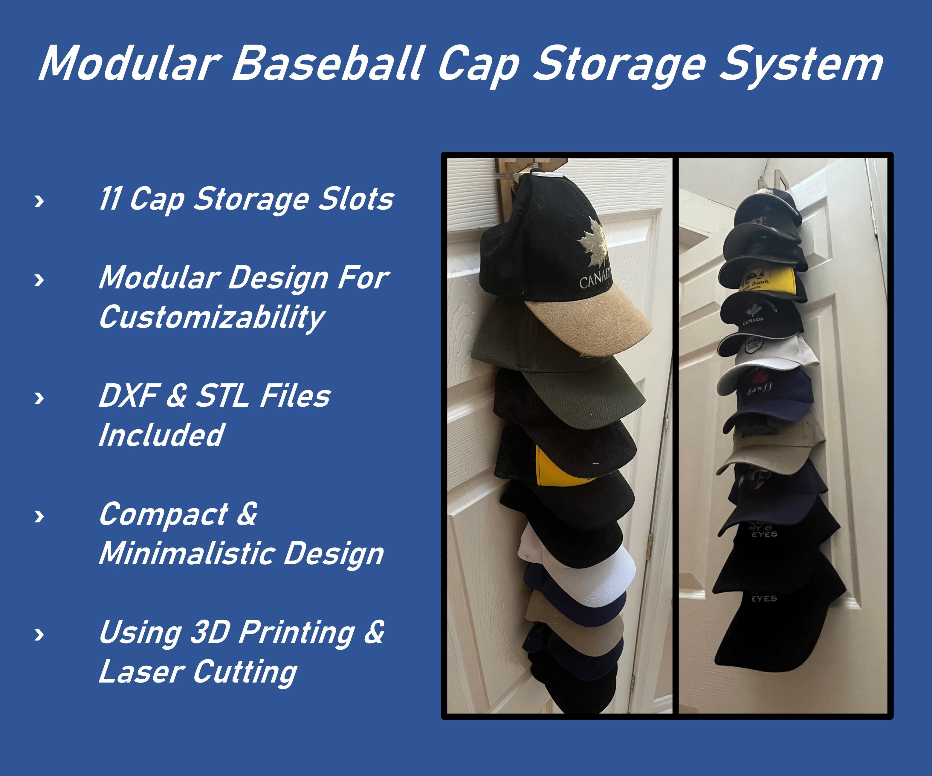
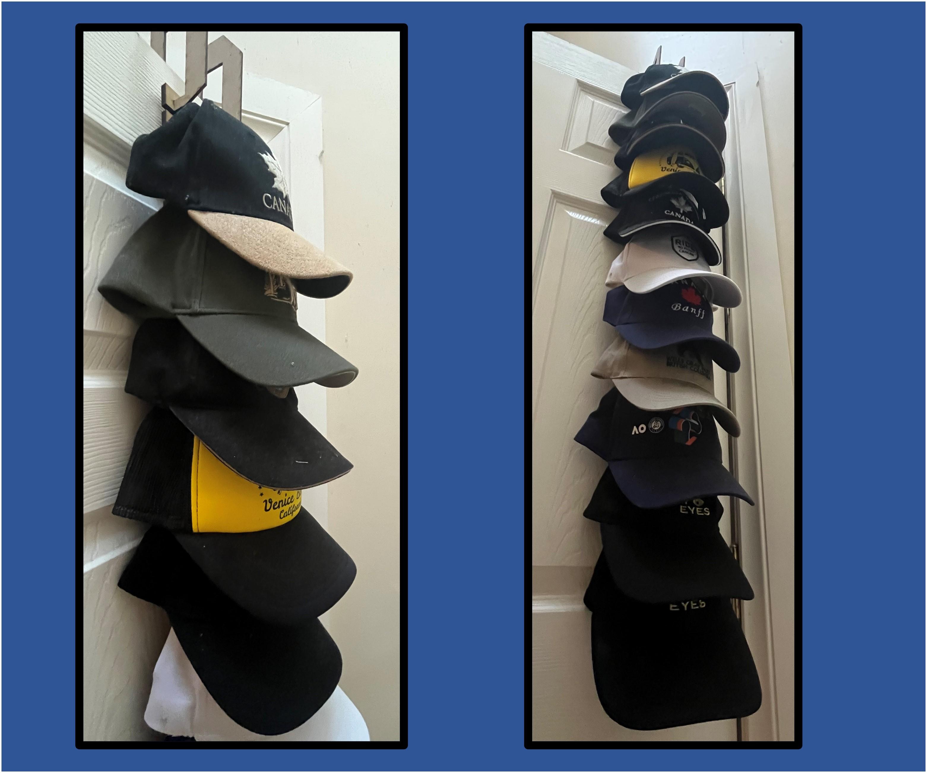
If you're like me, you'll find yourself picking up an assortment of various baseball caps over the years, which end up strewn around the house with no place of their own to go. For this project, I finally wanted to find a way to neatly and compactly organize my collection whilst still having them easy to access and pick to actually use them!
As well as being compact and organized, it was important to me to find a solution that was also versatile to easily fit my ever changing needs. To do this, each unit of the 11 available spaces for hooks/components simply slide into place and can be removed/interchanged just as easily. That way, you can easily design your own attachments for holding keys, scarfs, or frankly anything else you might need. To achieve this versatility and customizability, I decided to employ the use of 3D printing and laser cutting to help create this solution.
As always, all the DXF and STL files you'll need to finish this project are attached to the last step if you wish to replicate it!
Supplies
Tools
- 3D Printer (or access to printing service)
- Laser Cutter (bed size will limit project size)
- Short nose pliers
- Glue (Optional)
- Scissors
- Calipers
Materials
- PLA filament (roughly 250g)
- 6mm MDF sheet
- 80mm x 890mm
- 3mm MDF sheet
- 200mm x 80mm
- A4 Paper sheet
Software
- CAD software (I prefer Fusion360 which is free for students)
- 3D Printing Slicer (plenty of free options such as Cura, MakerBOT, etc)
Modular System Design
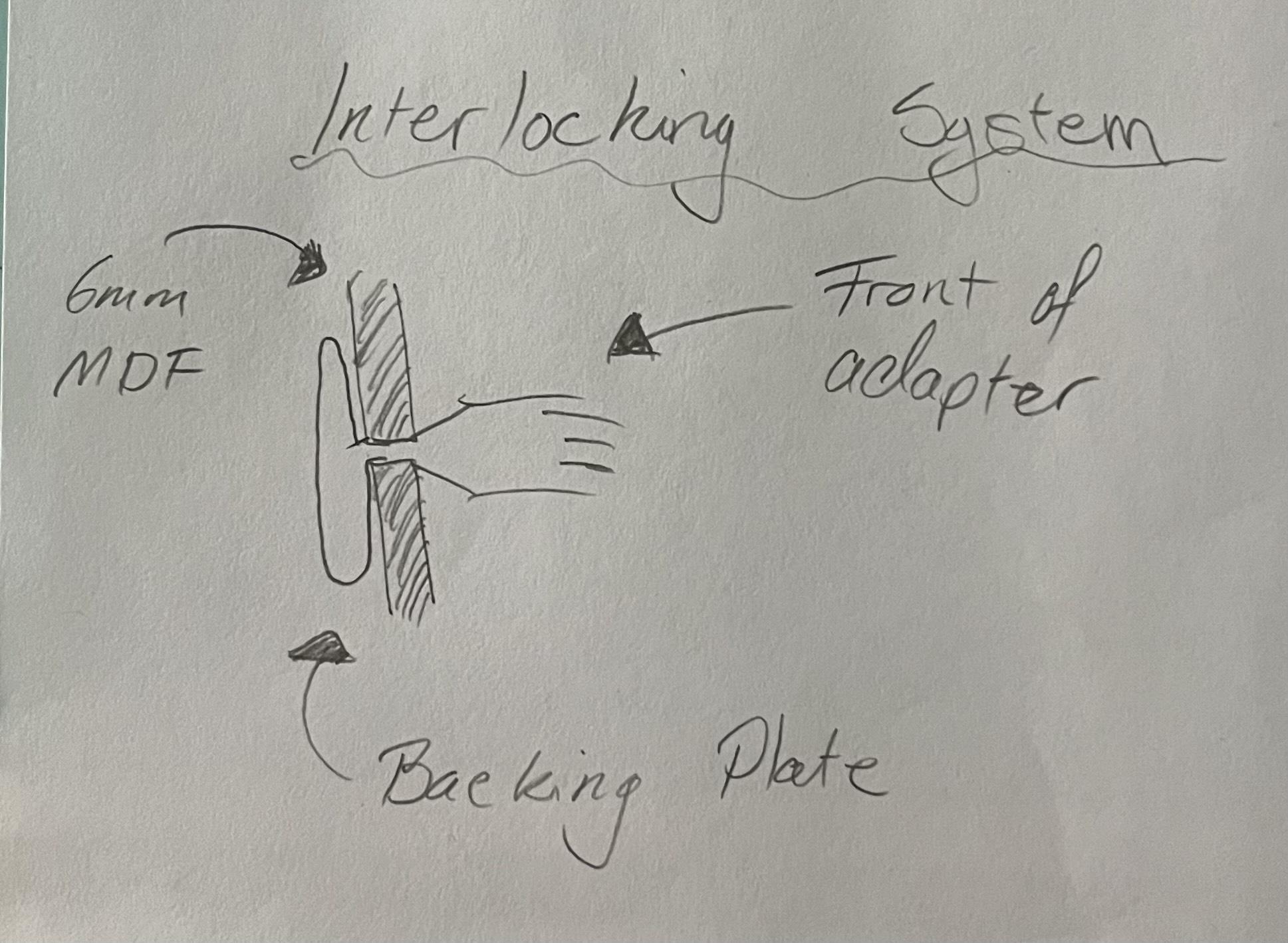
A key component of this design is the modularity of the system. As this project is a little bigger and I'm not 100% sure what adaptors I'll want to use most, the ability to quickly and easily interchange them at any time was an important consideration. Therefore, I designed the cap holding adapters to slide in and out of the frame of the design easily. This way, you can take the adapter off, put on/take off a cap, and slide it back on without having to do it on the rack still.
The modular system basically consists of a 5mm slot in the frame, with a 2mm notch to keep the adapter secured once it's slotted it, but can be overcome by just lifting the adapter and sliding out. Each adapter has a backing plate that extends above and below the slot to keep everything aligned nicely and 6mm long throat section that allows them to be slide between the 6mm MDF frame.
Initial Adapter Drawings and Measurements
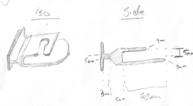
Now we have a basic idea for the mechanics of the adapter system, we can start working on some initial drawings to get an idea of how this will interface with the caps themselves. This process is usually quite a large back and forth going between measuring with the calipers and sketching solutions - so take your time and be patient. All of the caps in my collection have the top button on them and I thought that this would be useful to design around for a quick attachment. So, after measuring the largest diameter of the buttons to be roughly 15mm, I accounted for a 16mm slot and hole for the button to slip into, as well as an underplate that will slide under the button when the back of the cap is folded in. I added these measured dimensions to the sketches to make them easier to transfer into CAD.
The video in Step 7 demonstrates the use of the adapters
Cap Adapter Design
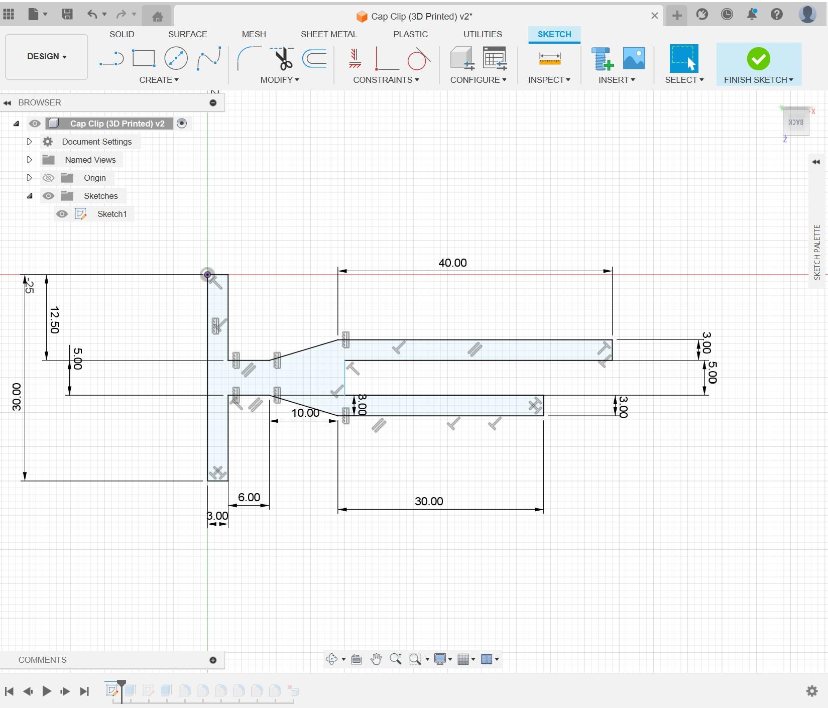
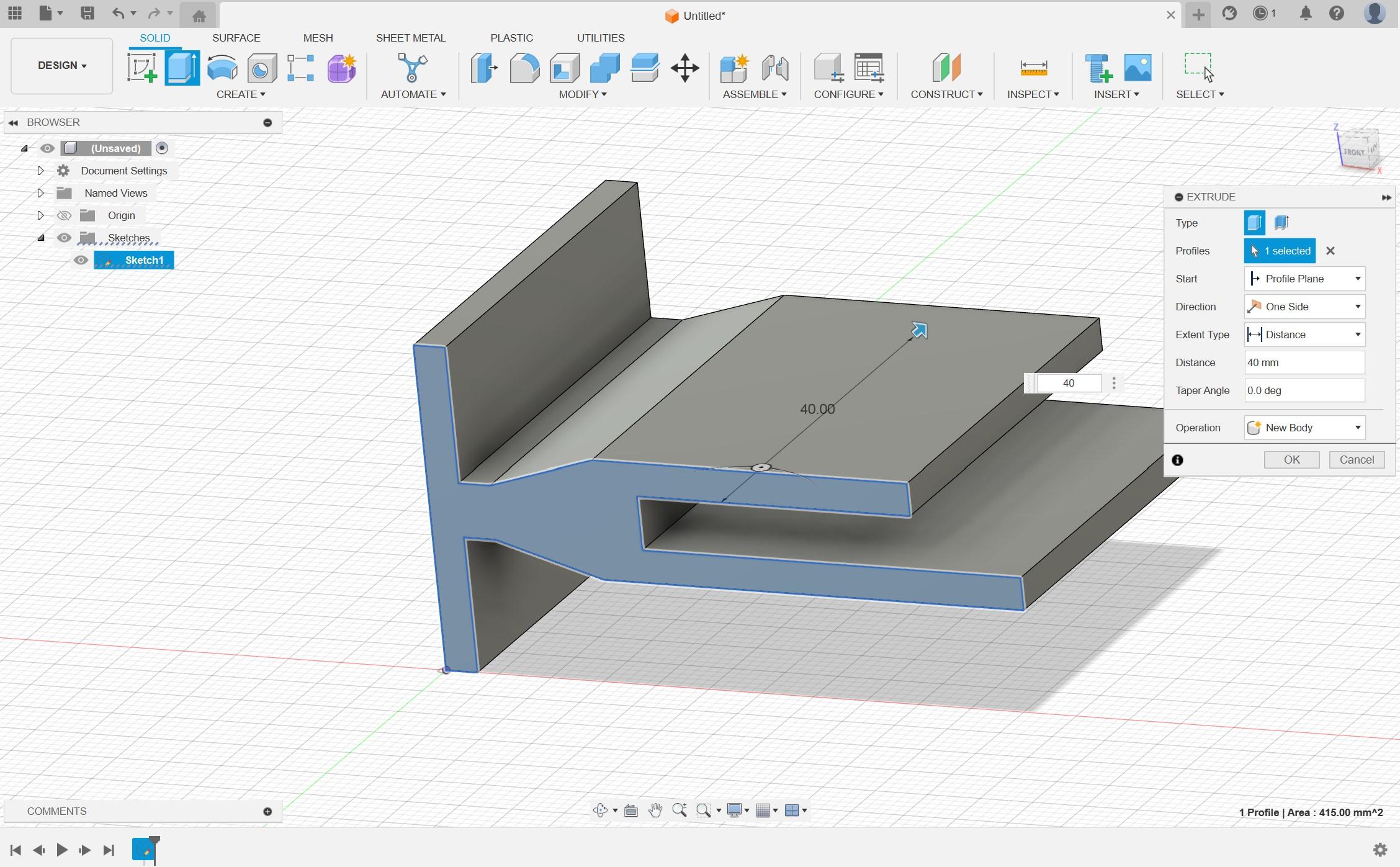
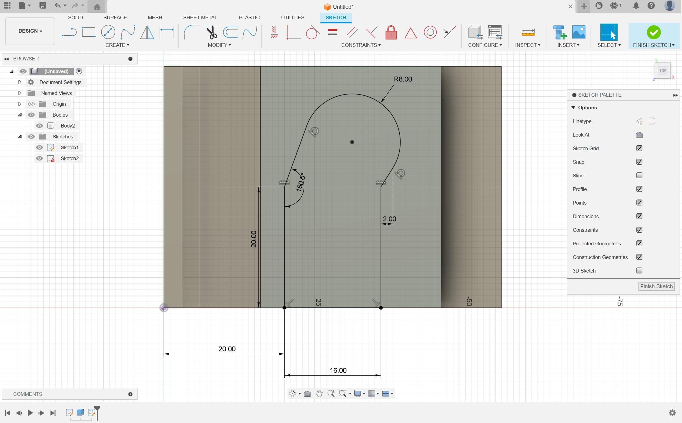
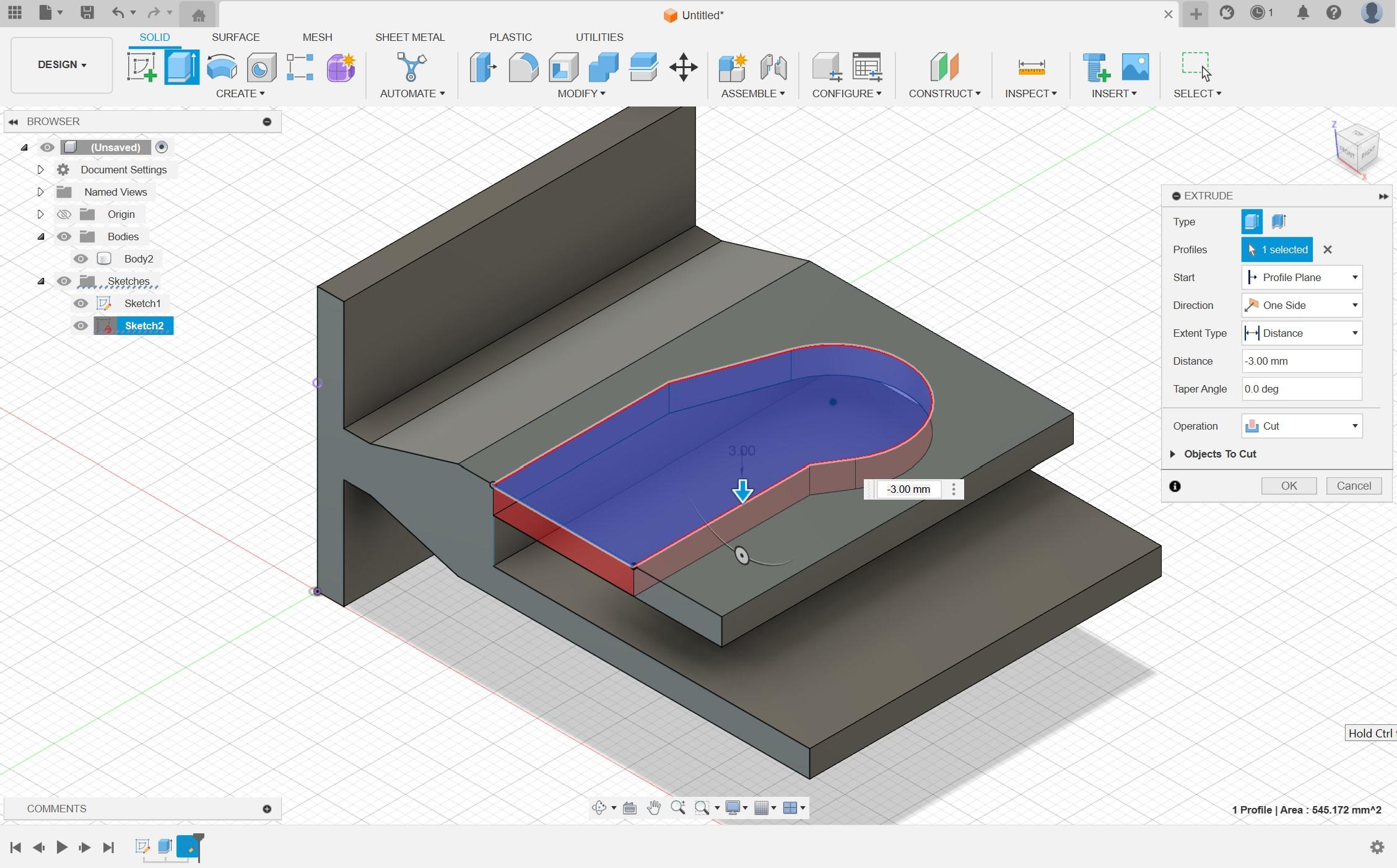
Once the rear section of the adapter has been designed to interface with the frame section, we can completely customize the rest of it. A hook, bowl, rail, or any other storage solution for your needs can be modeled in CAD from the simple base we've already set out, but due to my excessive cap collection I'm going to start there!
Whilst the geometry of the model is quite complex overall, it basically comes down to two perpendicular sketches in the software, one extrusion and a cut. As shown above, first I start with a side profile sketch of the system (the side view from the drawings above). During this, I don't worry about rounding the corners as this can be done later with fillets more easily. So it's just key to get our dimensions set, then we can extrude this sketch to our desired width.
After this, all we need to do is create a sketch on the top face of the model where we'll make a cutout for the cap button slot. To do this simply click the top face, then new sketch to create the slot using the line tool and an arc for the circular portion at the end. Then just extrude this through the top layer to remove the slot.
Fillets and Export
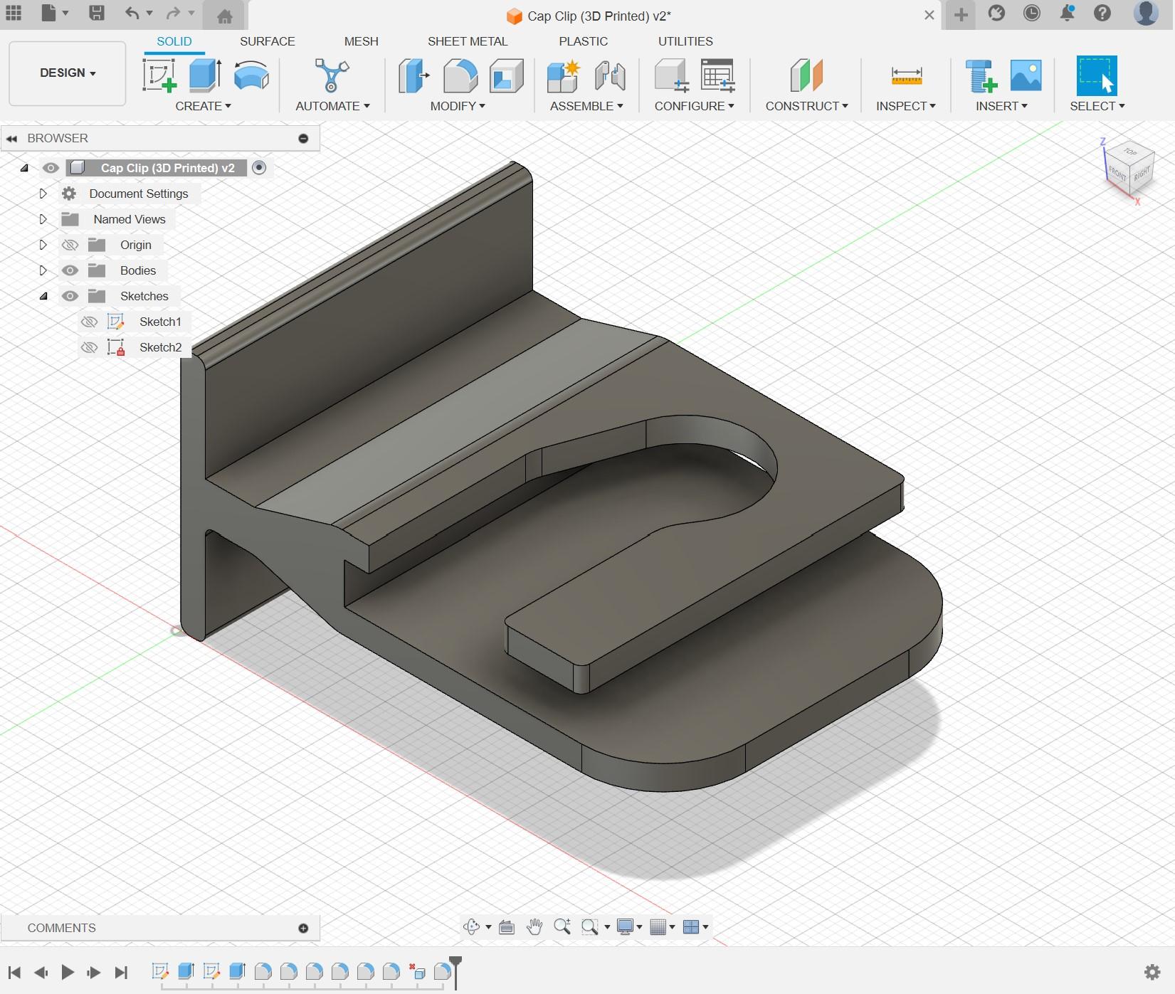
Now we've got our rough 3D shape we can start refining it with fillets around the body as shown above. It's important that you do not use fillets on the corners that will interface with the wooden frame, because this will prevent them from being able to slide into the frame as desired.
Once we have our final model, we simply will export this as an STL file ready to use in our slicing software.
Slicing and Print Orientation
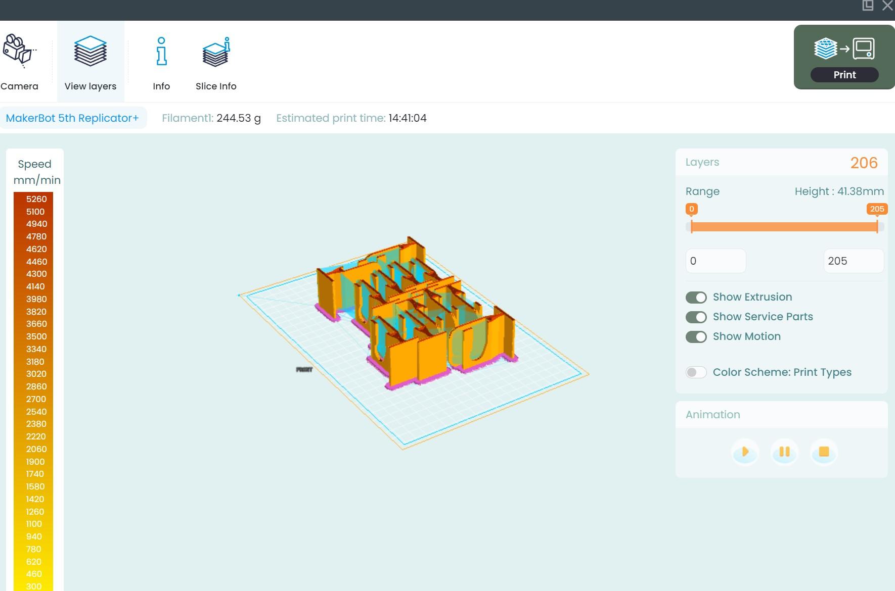
Now we have our model, we can begin to prepare for printing. For this project, I printed using a cloud software to order my prints, but the inbuilt slicer software is pretty much identical to the free and open source options I usually would use.
The only real consideration for slicing this project is the print orientation. I decided to print on the side, with the open face of the button slot facing away from the bed. This orientation was ideal as it meant no support structure was needed which would result in a rougher surface and more surface imperfections to clean up later. I used 20% infill and a raft which gave great results for me.
*Note: All printing was done on a MakerBot Replicator+, but any machine should be plenty sufficient for the purpose
3D Printing
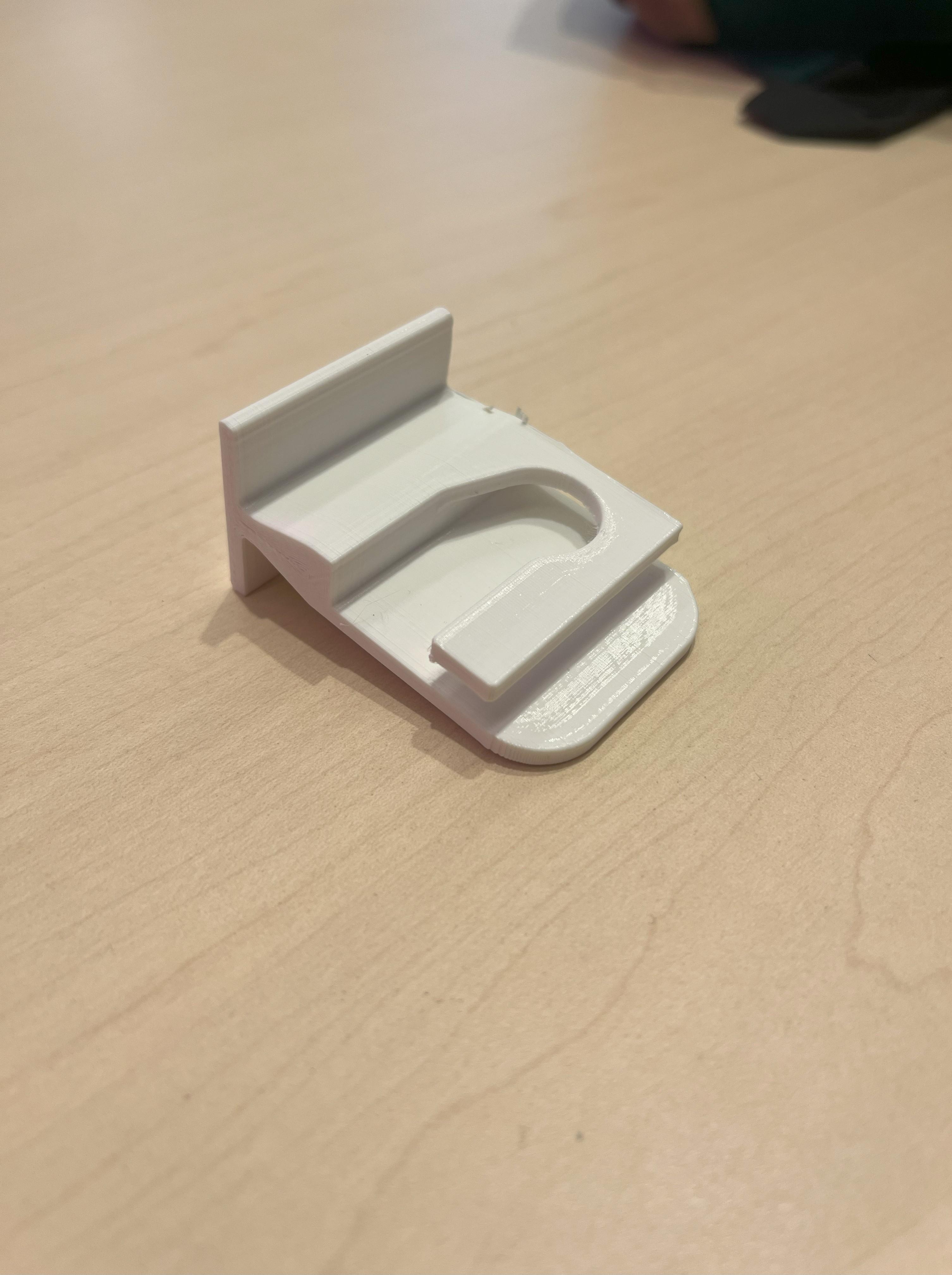
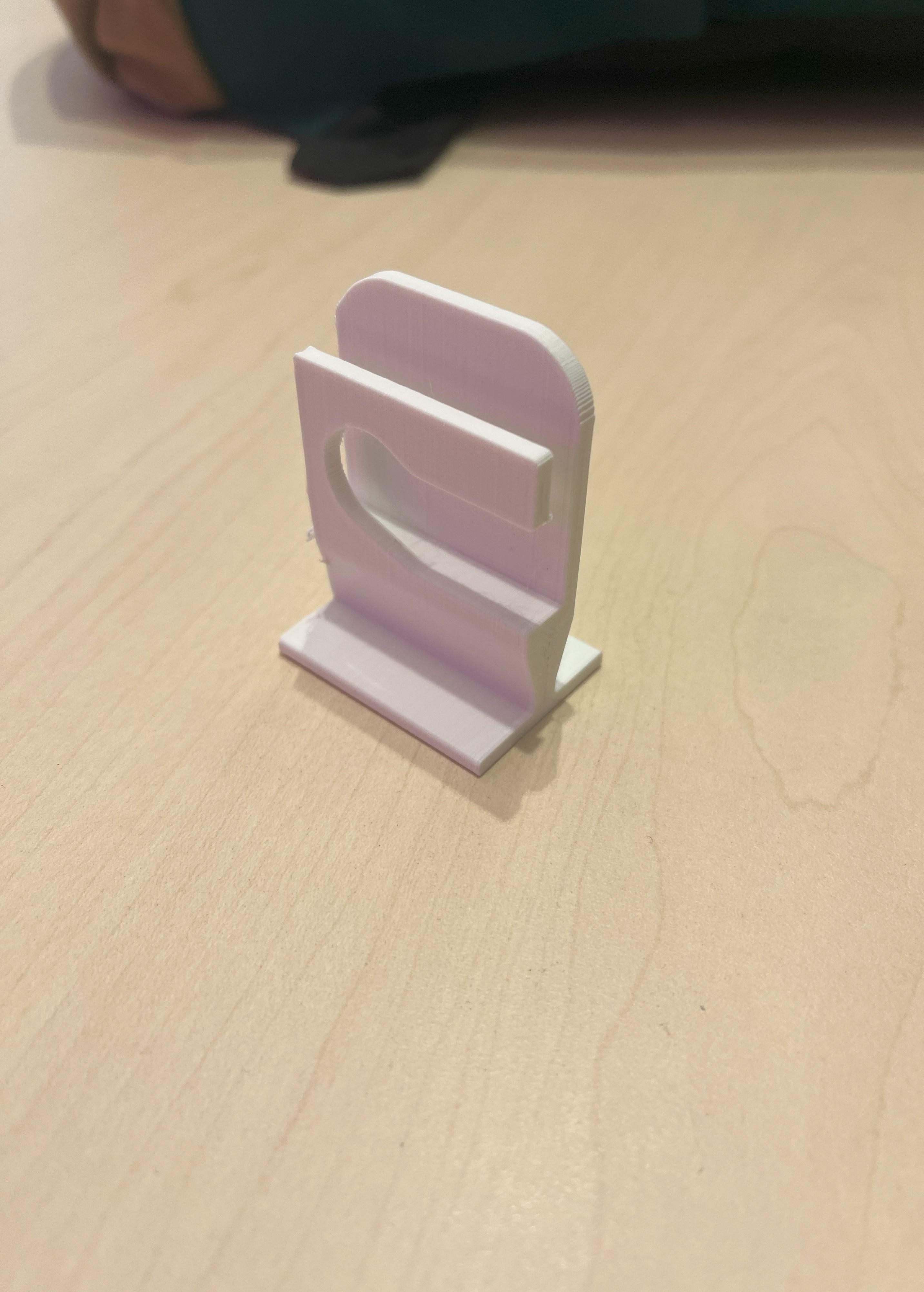
Once the bed is set up it's time to 3D print the models. Export your build plate as gcode and send it off to the printer to do the hard work!
Testing Fit and Tidying Up Prints
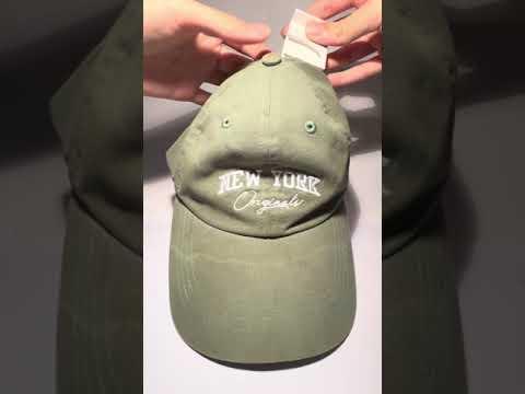
As the printers I was using were third party, I couldn't set them up myself and there was quite a noticeable amount of stringing between parts and part features, which is usually a sign of water absorbed into the filament. This isn't ideal, but with a pair of short nose pliers, I could tidy them up to a pretty satisfactory standard.
The finished part is demonstrated in the short video above :)
Designing Frame
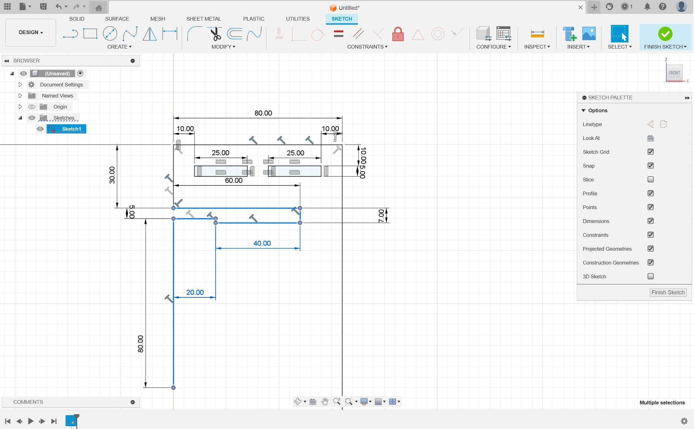
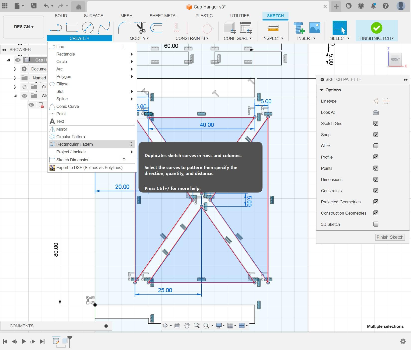
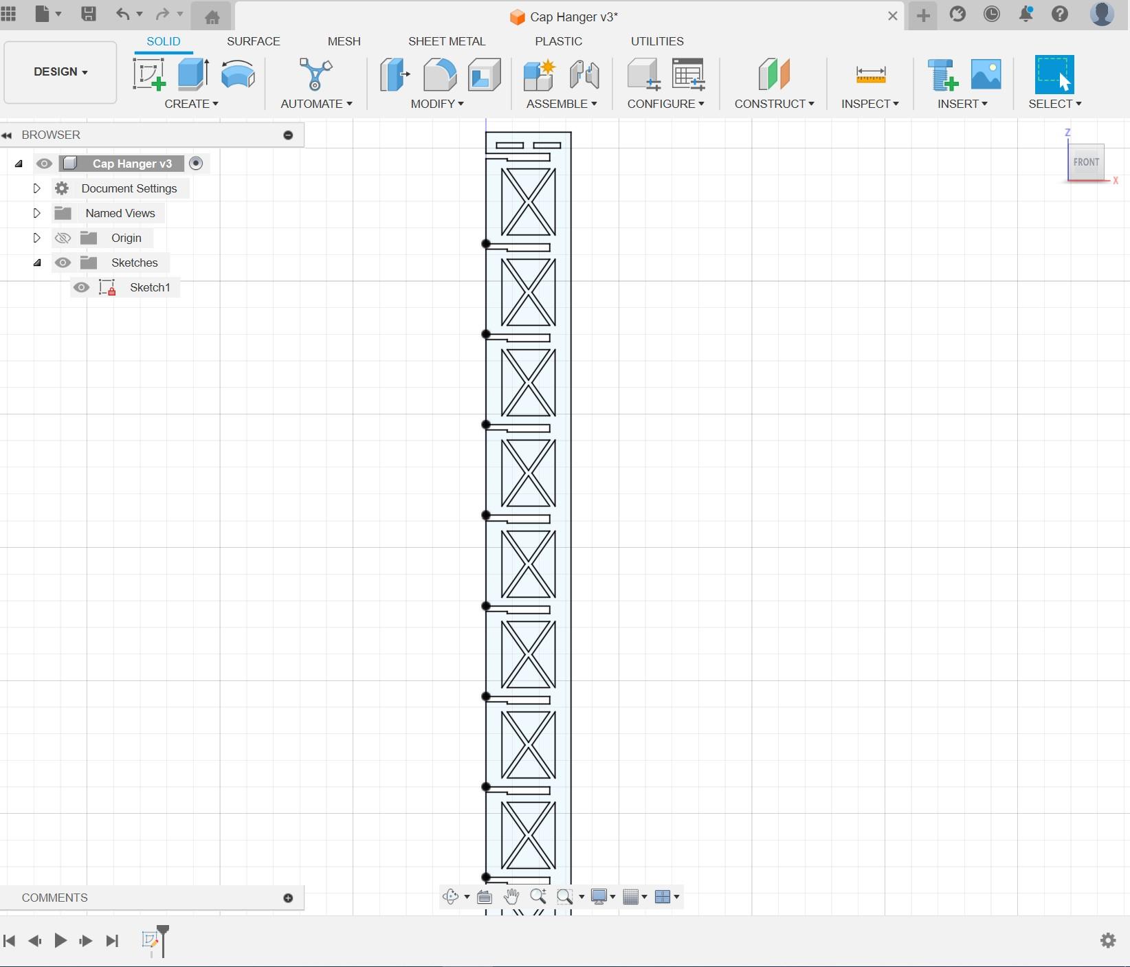
Much like the process of design the adapters, I used the baseline measurements that I made earlier to design the slots of the frame. The idea for the slots is super simple, just a 5mm slot by the edge, which opens to 7mm in the center. This means that the adapter sits down in the little cutout and won't slide out of place until you intentionally lift it to slide out.
I want the caps to face forward with each design identifiable, but still compact, after some playing around with the hats in real life I found that I could space 11 of them on one 890mm frame. To create this in the software, I used Fusion360's rectangle pattern tool to duplicate one of the slots down the entire plate.
Similarly, I used the same pattern tool to cut out the truss sections from the wood. These sections should make the entire frame much lighter and put less stress on the joints at the top.
Measuring Hook Dimensions
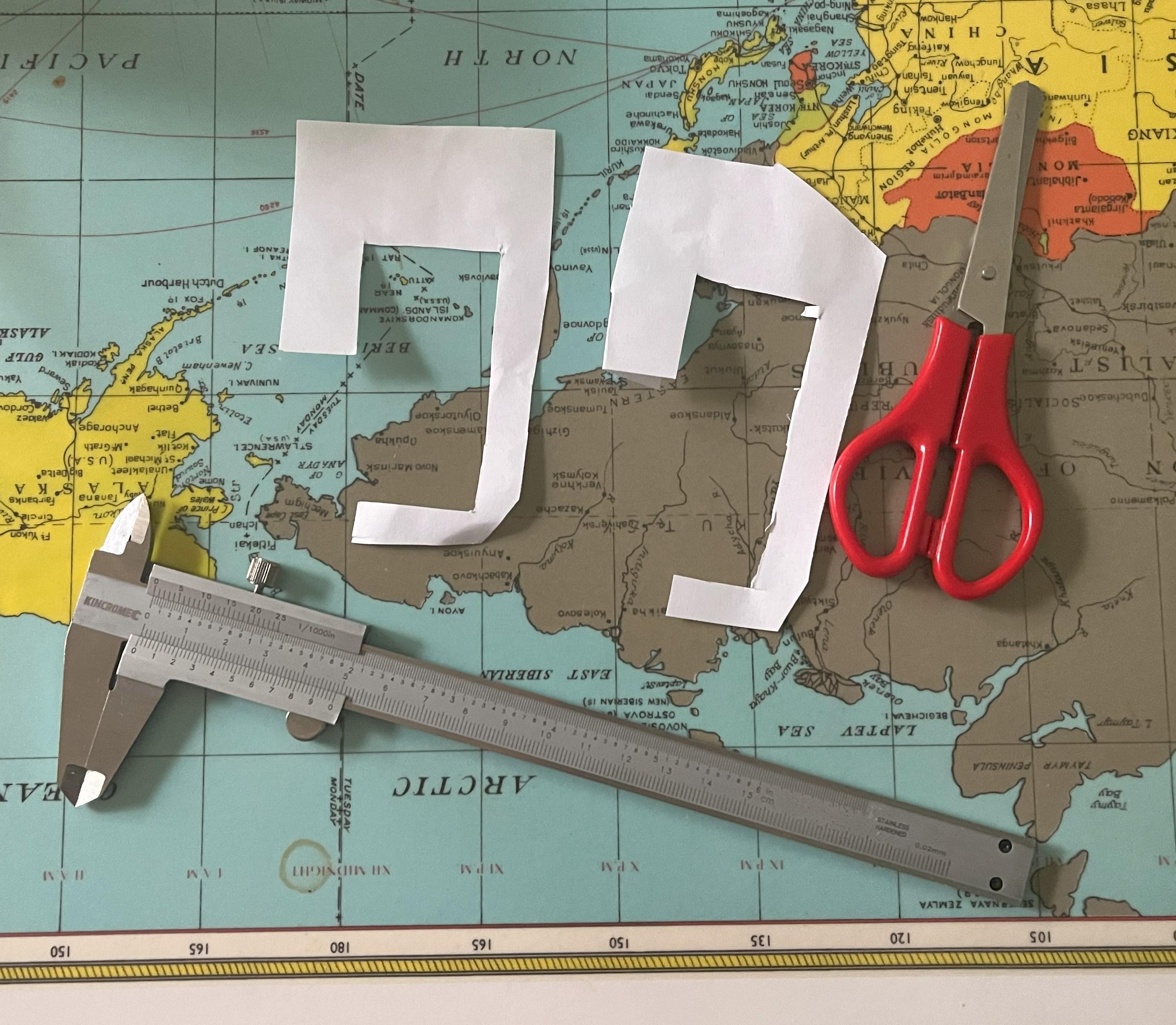
Time to bring out the calipers again, because we need a way for our completed frame to be hung up! I designed the rails in the frame to be very versatile so that the frame can be attached in many different ways to suite whatever may be necessary. For my own use, I'll be hanging the rack from the side of my wardrobe so I decided to make some dedicated hooks.
To measure the size and fitment of these hooks I started out with my calipers, however, I found that the awkward geometry of the top trimming of the wardrobe made getting accurate measurements challenging. So instead, I created various paper cutouts of the rough design I was after, and used them as templates to test the sizing and structures that would work. Once I had a finished template that seemed to fit all dimensions and requirements, it could be modeled in CAD.
Other ways to mount
It would also be easy to wrap some wire through the mounting rails at the top to hang just about anywhere. Or even some extra screw holes could be drilled if a more permanent fixture is in order.
Designing Hook
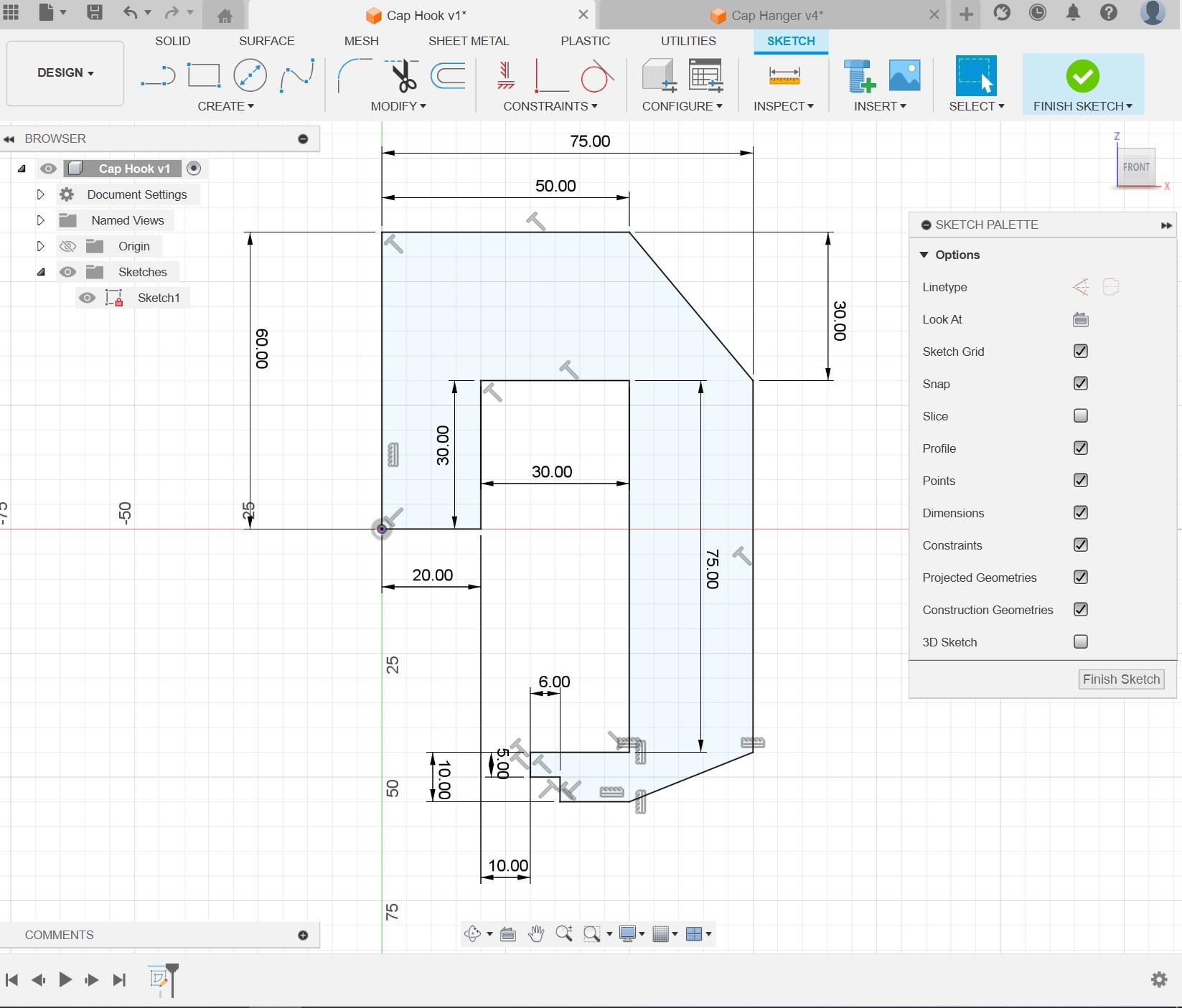
Designing the hook was really straight forward after the work that was already done in constructing a prototype template. It was then as simple as sketching the same shape in Fusion360 and transferring measurements into the software from measuring the template. This gave a perfectly fitting final result and is a good tip to use when designing components that have to interface with complex geometries.
Exporting Files
Next up is exporting our file ready for laser cutting or 3D printing. This is as simple as right clicking on the sketches and selecting "Export as DXF" and saving to your design folder. This format makes it easy to import everything into other software without losing any detail.
Laser Cutting
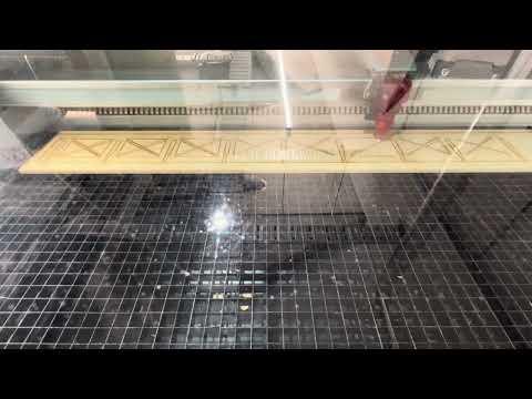
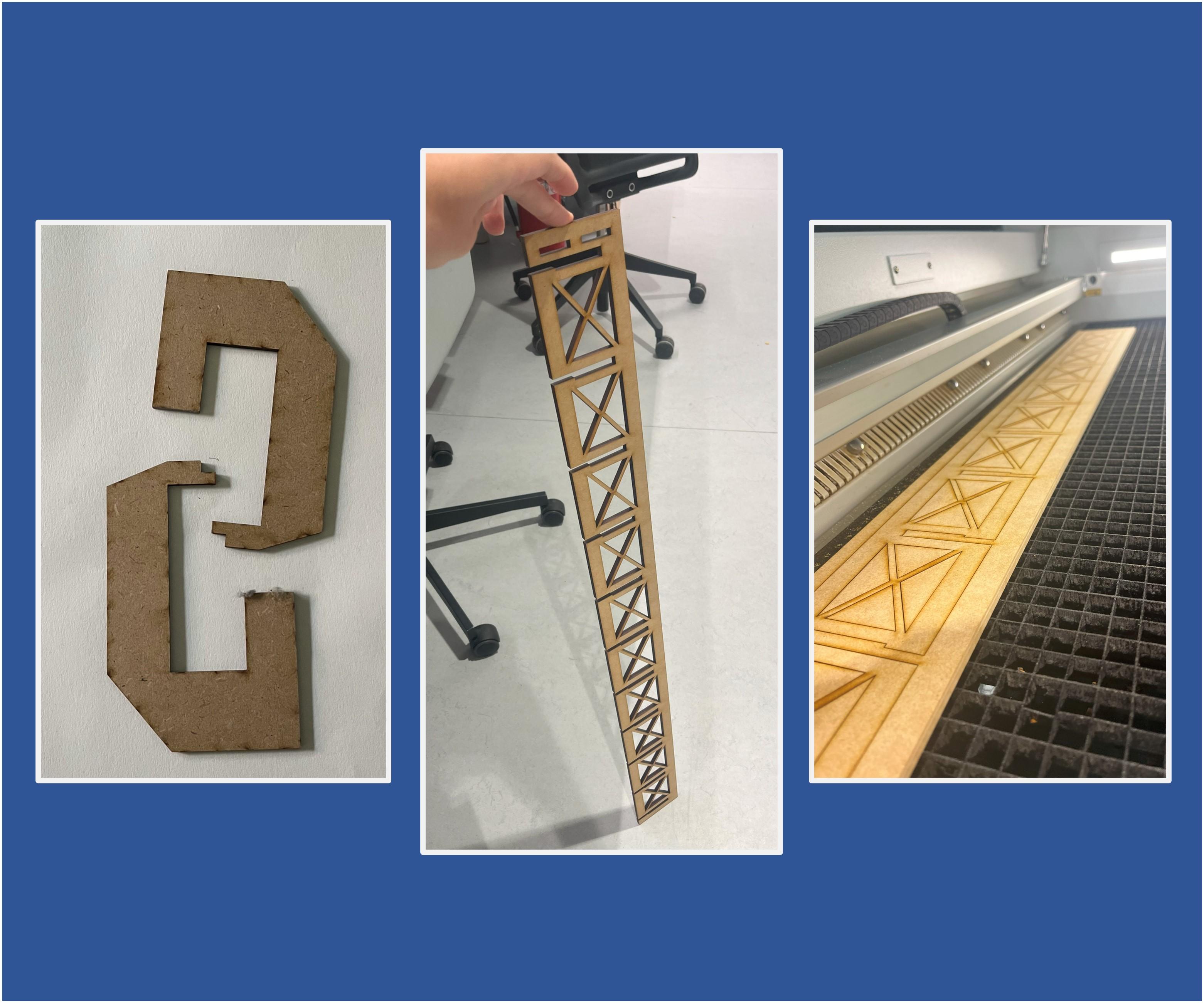
This step is the fun one! Time to get laser cutting!
Once you have your completed DXF files, you're ready to set up for laser cutting! I used a Trotec laser cutter for this project, so the process was as easy as importing my selection into CorelDraw – and then printing the page to Trotec Job Control.
It's always important to make sure your page is the right size for your laser cutter dimensions so that everything runs smoothly and predictably, and components don't go beyond the workable area.
Putting It All Together
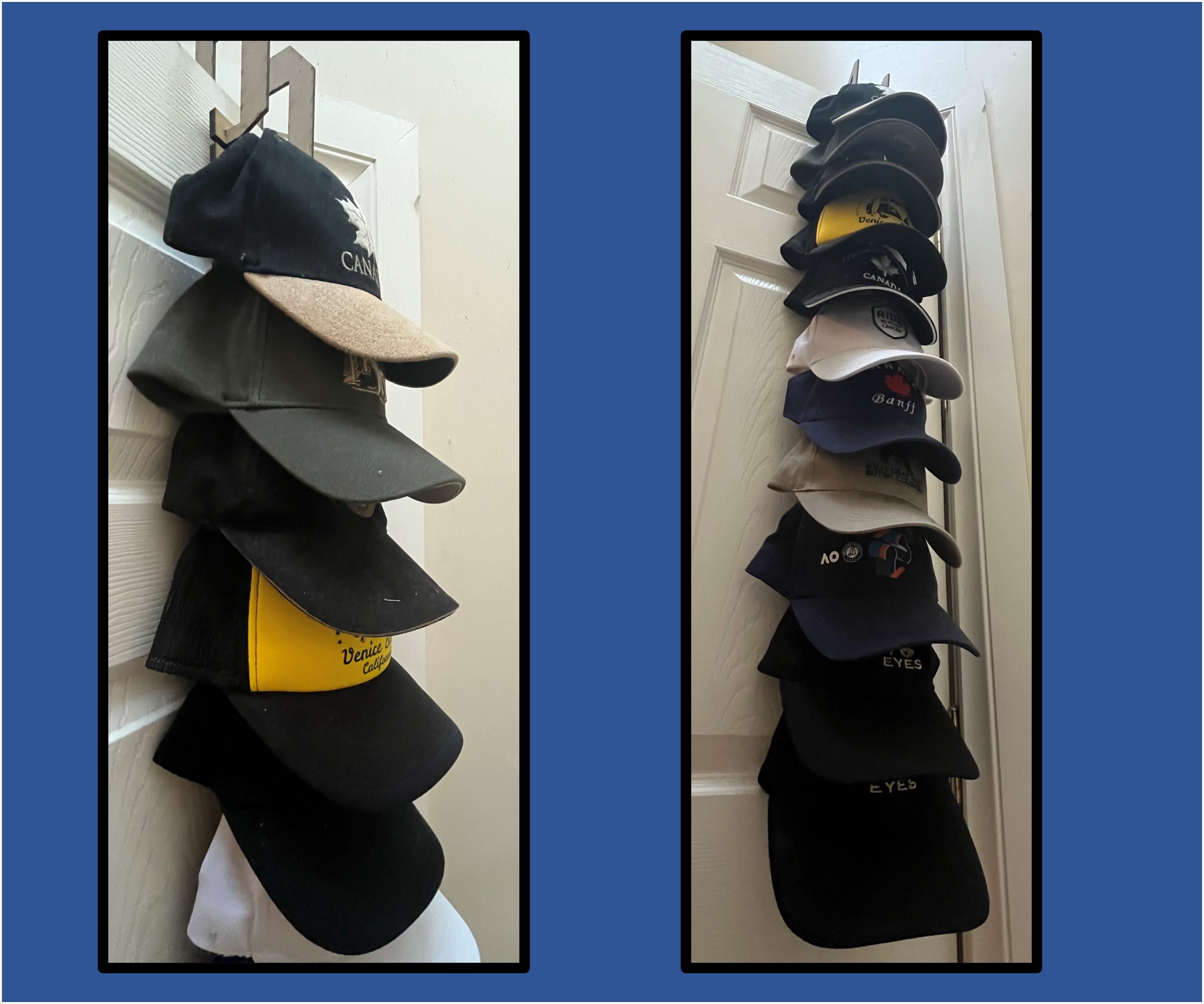
Now we have our parts its as easy as sliding everything together! The hooks, or whatever your hanging solution, should sit in rails at the top of the frame nicely and have the rack hang flat and flush. When using the rack, I find it easiest to attach/detach the adapter to/from the cap whilst separate from the frame. That way everything is more easy to access and maneuver. Then, once the hat and adapter are interfaced, the adaptor can simply slide onto the supporting frame. Also, if you're sure on the attachment of your top hook, you may use some wood glue to lock them in place keeping everything secured.
And that's that! Each frame supports 11 attachments, however, the length of each frame is only constrained to the dimensions of your material and laser cutter (or not if you use joinery) so the customizability is frankly endless.
Additional Changes and Improvements for V2
Double Columns
An idea since I finished this project is to widen the rear frame and add a second column of hats. The design would be incredibly simple and could just be a straight reflection of what is already in place, doubling storage. The increased width could also allow for wider attachments that may span both slots in one row. This symmetry might also be beneficial in ensuring the frame doesn't sag at all, however, I haven't noted any issues with sagging myself.
Materials
Acrylic would be another really cool material for the frame, especially if the frame will hang in front of or near any windows - it would give an interesting floating visual effect. Acrylic may also be stronger and improve longevity