Bandsaw Plastic Table Insert With Fusion 360 for Lumberjack Tools BS228mm 9"
by Kevr102 in Workshop > 3D Printing
445 Views, 2 Favorites, 0 Comments
Bandsaw Plastic Table Insert With Fusion 360 for Lumberjack Tools BS228mm 9"
In this Instructable I will show you, using Fusion 360 how I make a Plastic Insert blade guide for the table on my bandsaw.
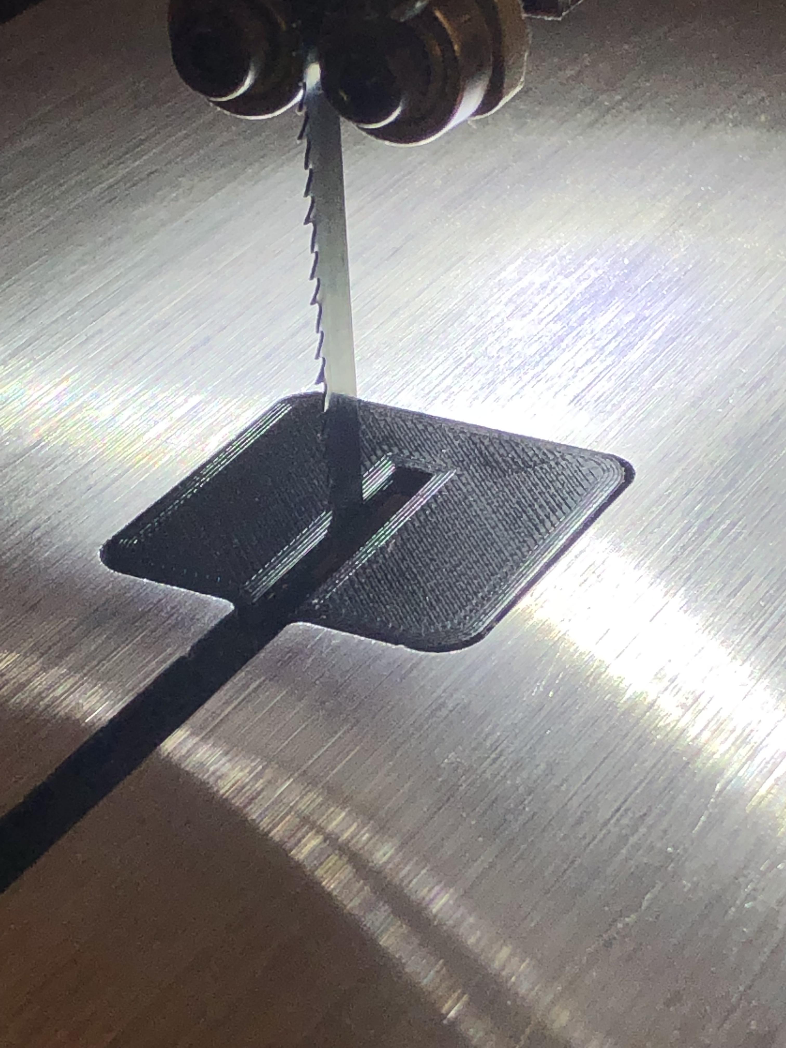
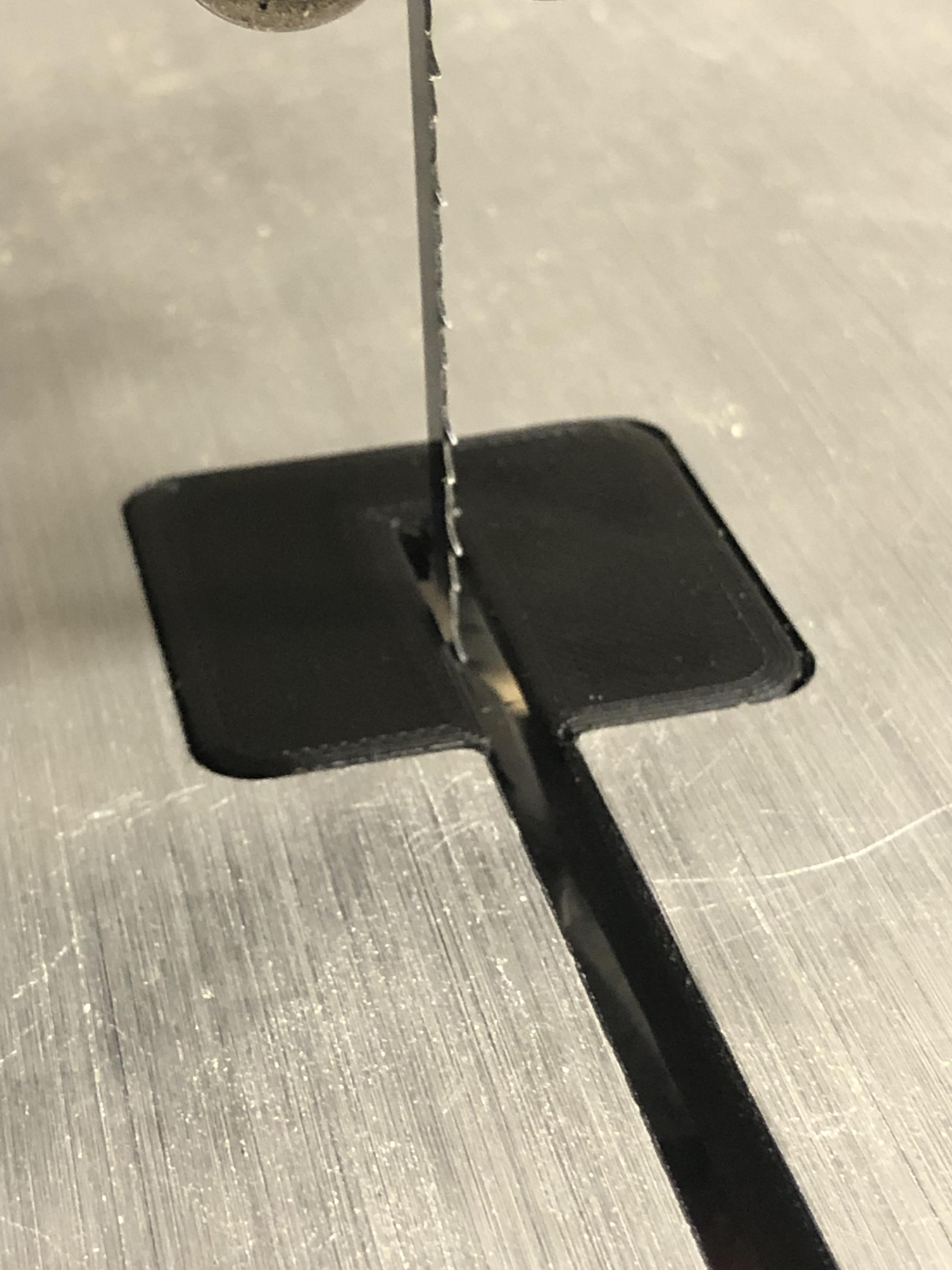
The reason for making a new insert is because the original insert sits too shallow in the recess thus each time you try to push a narrow piece of timber through it snags the table, at times messing with the cut, I'm no expert when it comes to bandsaws but this insert should be flush in turn making for a smooth cut, I need to rectify it because it's starting to rattle me.
A word of good advice with bandsaws, this advice was given to me by a guy with 25 Years or so in the Bandsaw Manufacturing Industry, his advice is as follows, "Never go below a 10" bandsaw even its only for hobbiest/diy duties ,even if it does state its a professional Bandsaw, and get a decent blade straight away" there ya go you read it here first! Apparently the quality is so much better just with paying that bit extra, this is my 2nd Bandsaw, the first one ended up in the scrap bin not outliving its initial guarantee, hopefully with a few amendments this one wont be going the same way!
Anyway on with the Insert:
Supplies
Fusion 360
3D Printer
1.75 PLA
Designing the Plastic Insert.
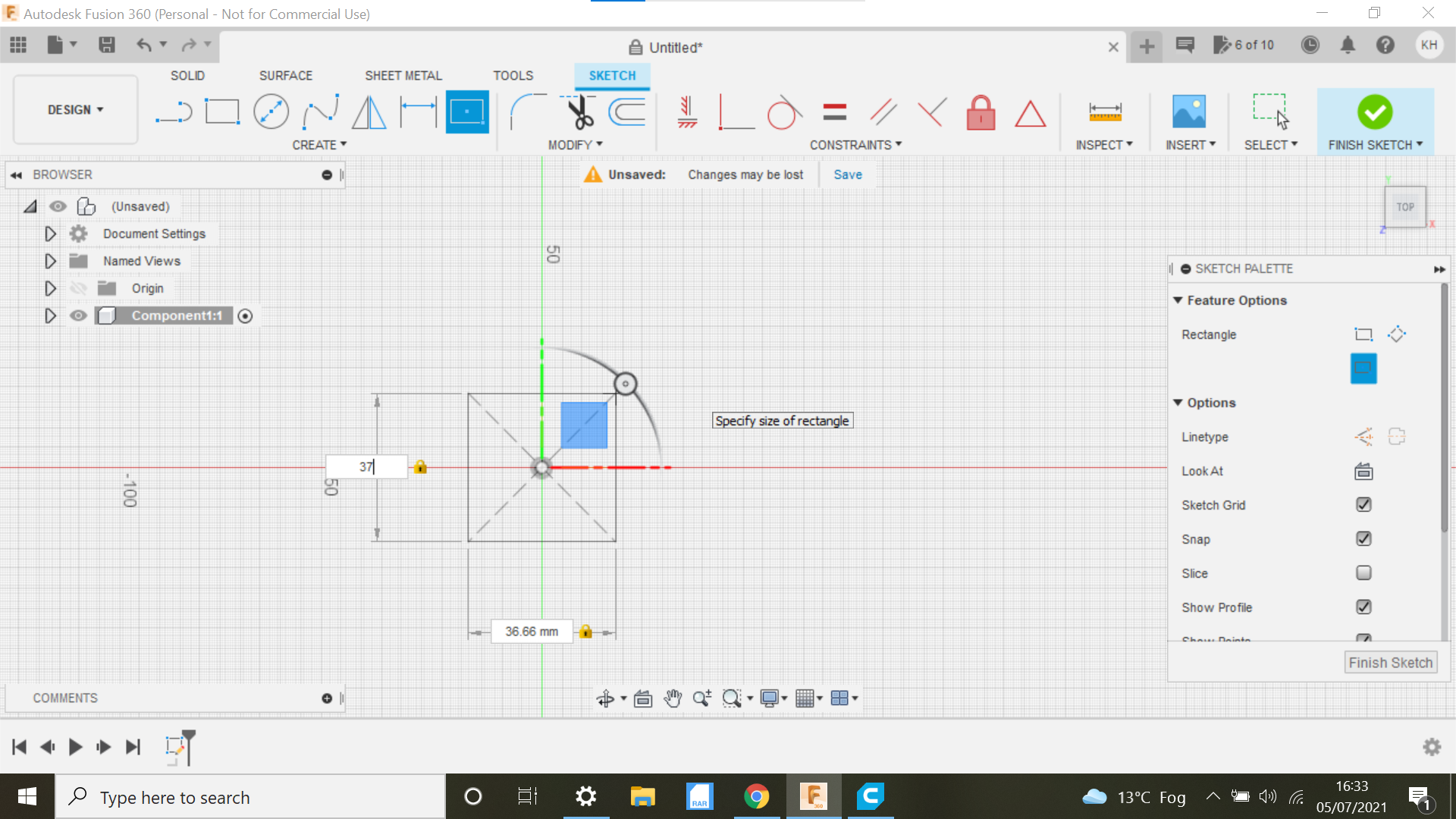
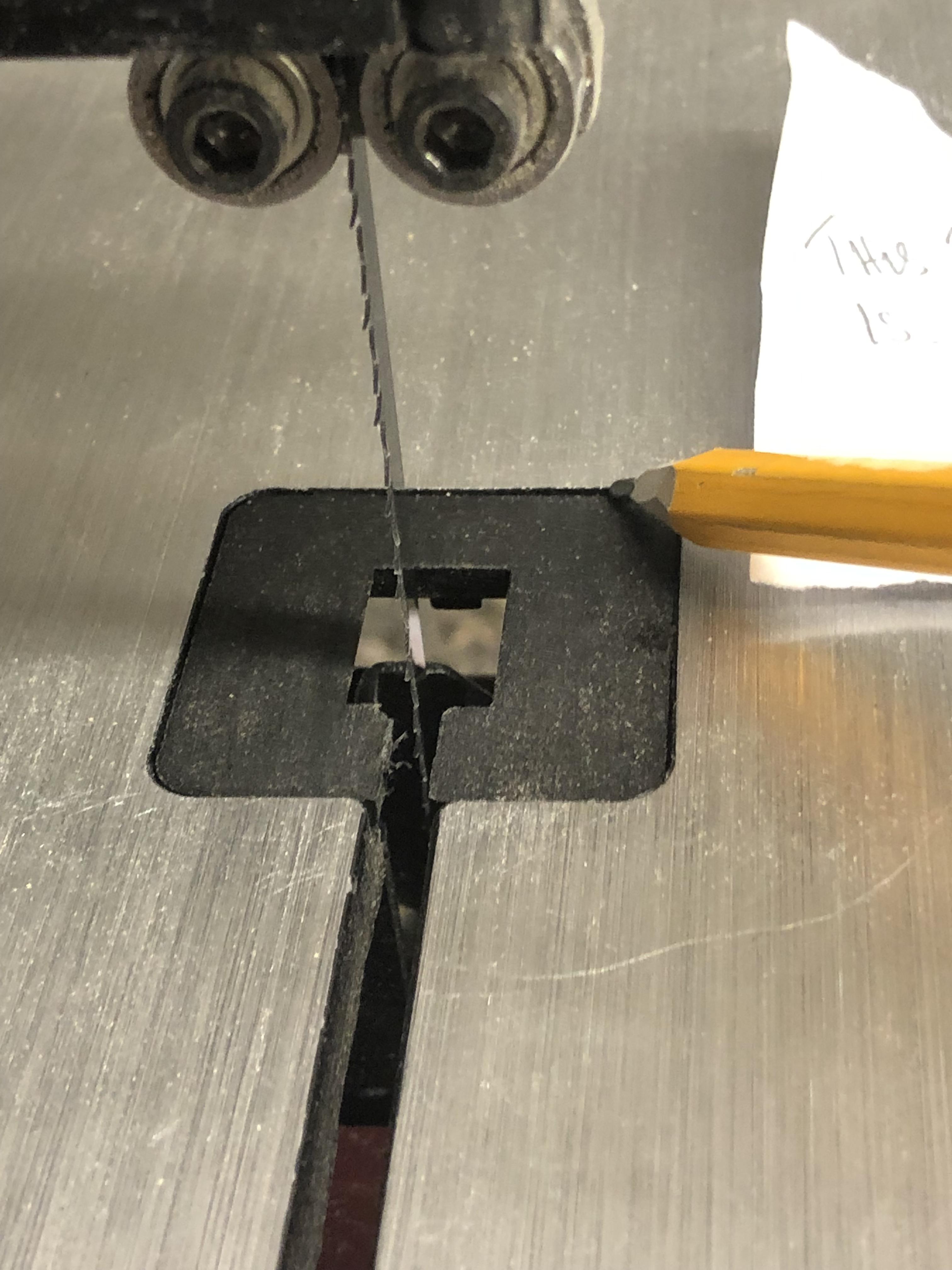
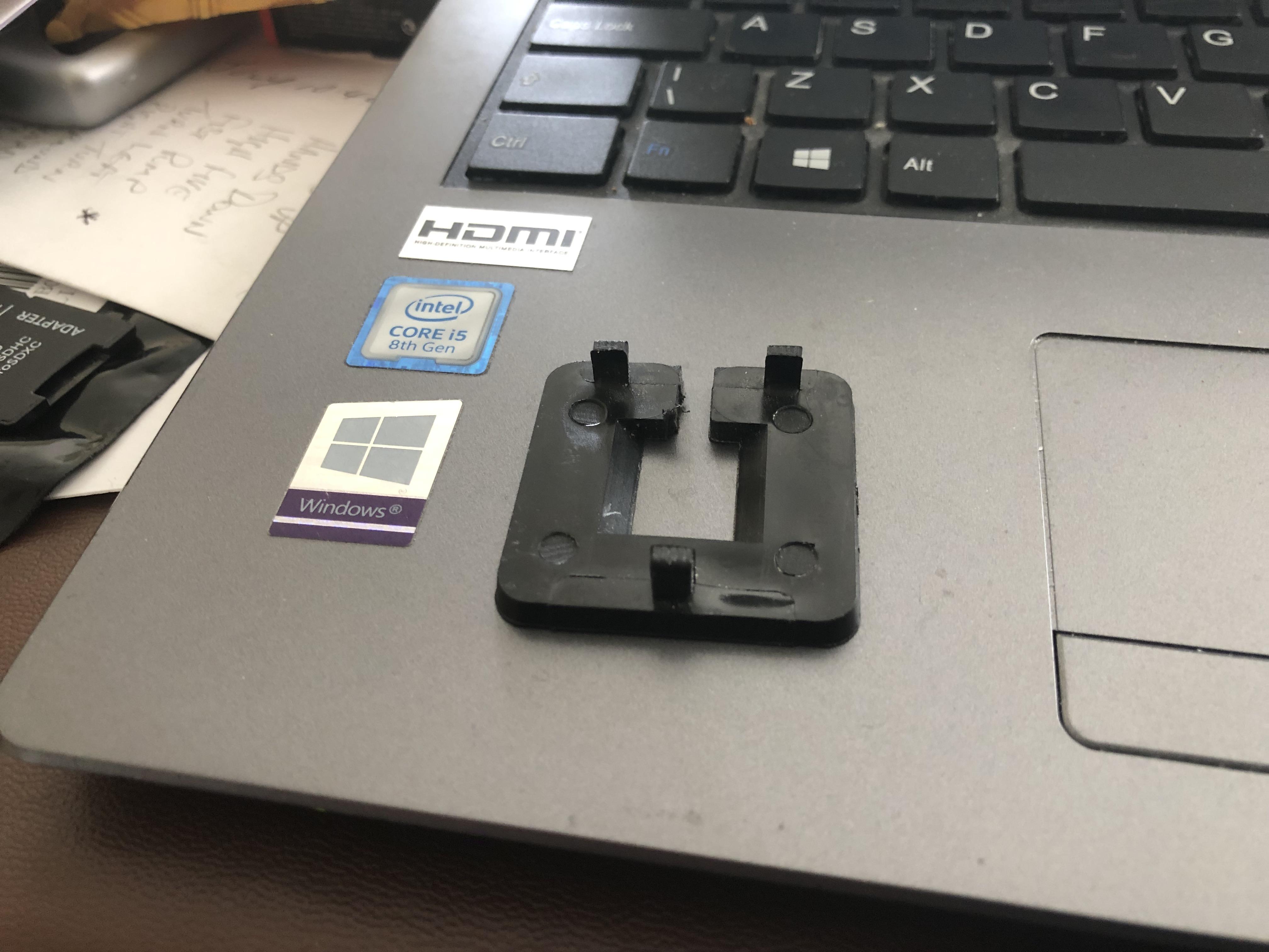
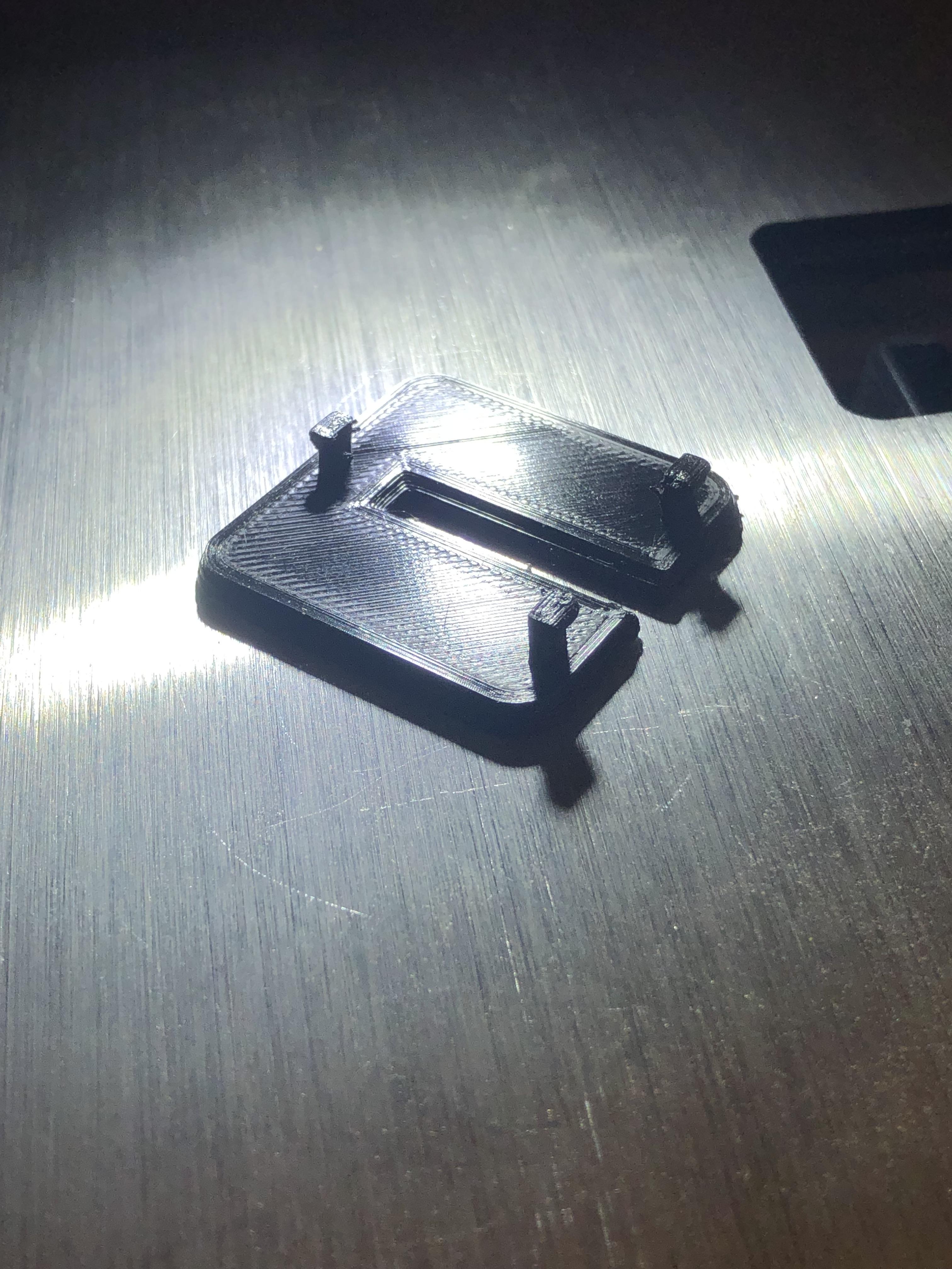
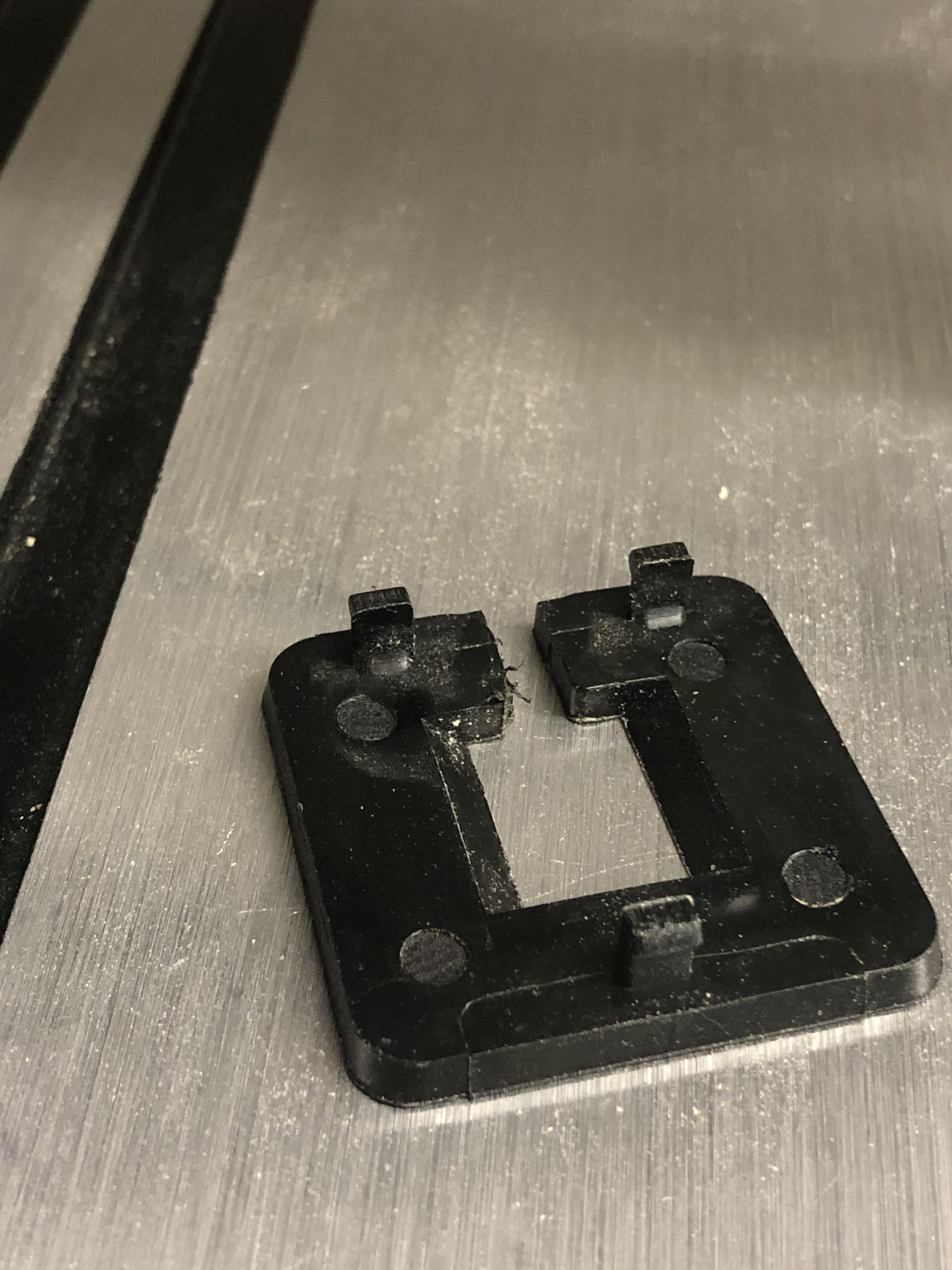
Usual format when opening Fusion 360, Start a new component and select(In this case) the top plane, it's not that important but when it comes to 3D print, the component usually will be facing the right way up, this component will be sketched upside down for ease of printing, the original insert has 3 tabs, I'm not sure that these actually achieve the desired effect as the insert can be pushed out with a pencil, maybe just a guide, who knows.
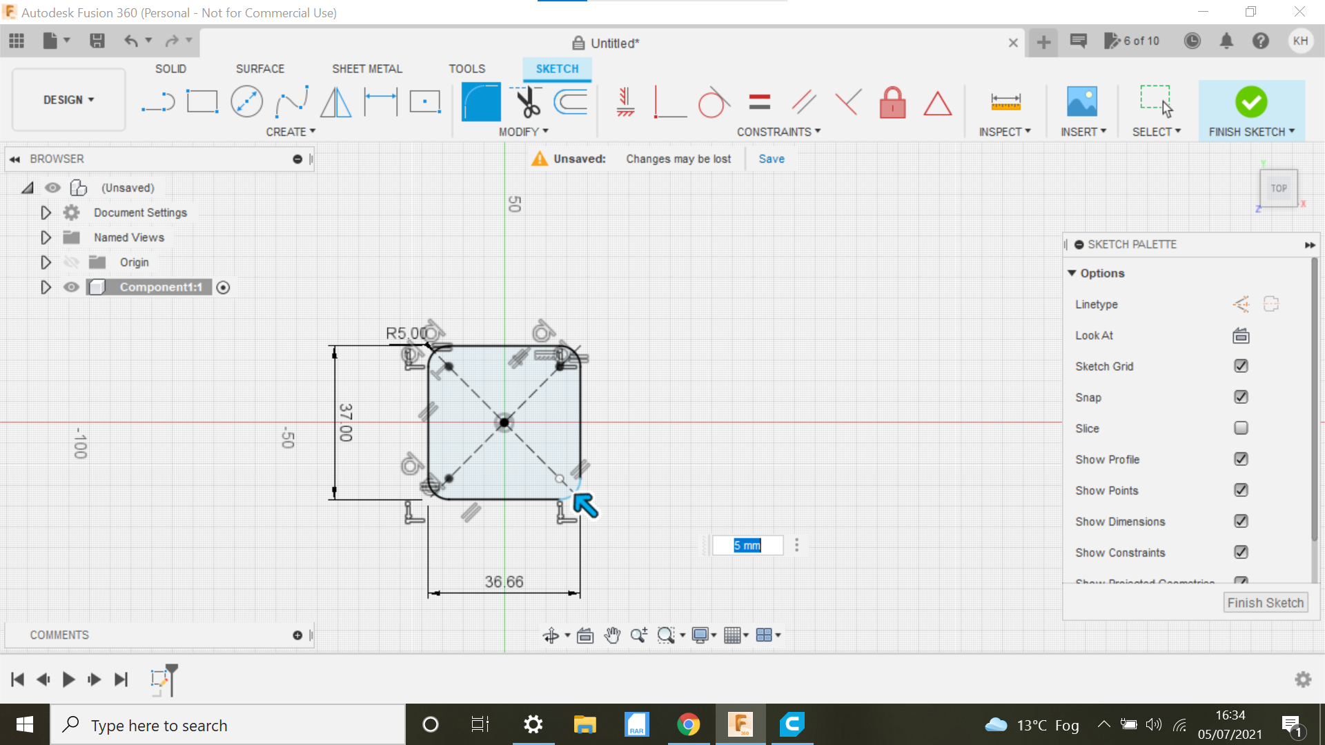
The initial sketch is a centre square with the dimensions as shown, create fillets @ 5mm on each corner.
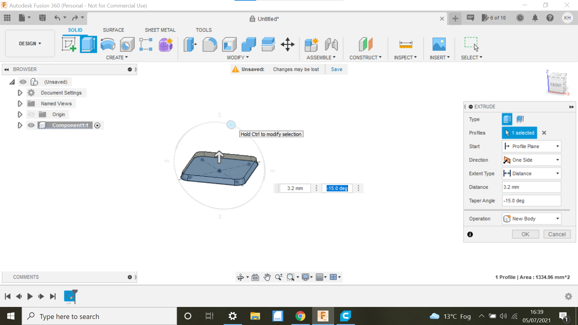
This insert I'm going to extrude to 3.2mm the original being 3mm, its a prototype I can always adjust later, I want it to be flush.
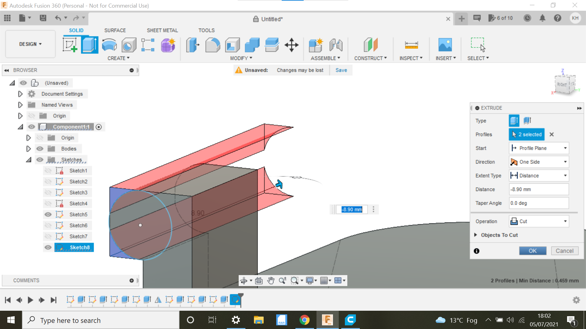
When you extrude, you will see an arc above the extrusion, drag the blue circle to create a 5mm draft to the insert inwards as per the original.
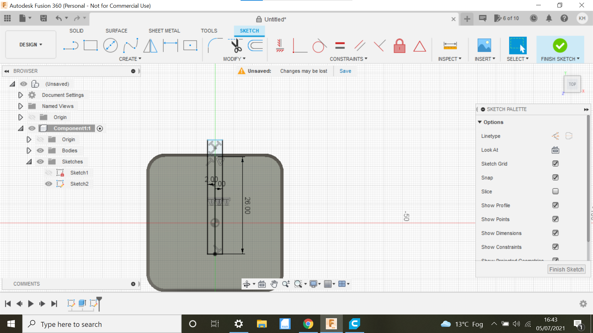
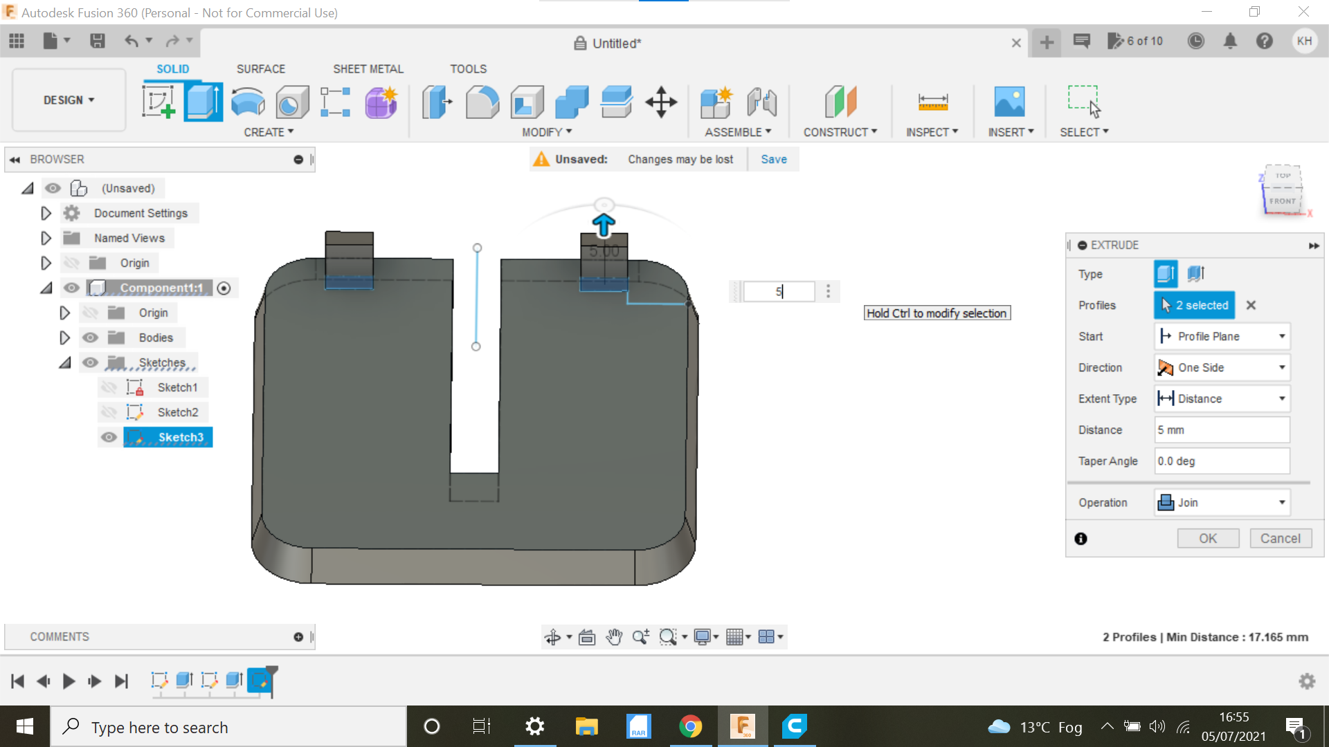
The next job is to create a line from the centre of the insert on the drafted edge down 26.26mm same as the original we will offset of this line to 2mm either side, then create a line across the top and bottom of the offset lines creating a rectangle, delete the centre line at this point and extrude the rectangle to say -20 cutting through the material, the original has a bigger rectangle encompassing the blade, but I'm finding pieces of wood drop though this gap sometimes snagging the blade, I will try it like this for now with a 4mm gap and see what the outcome is.
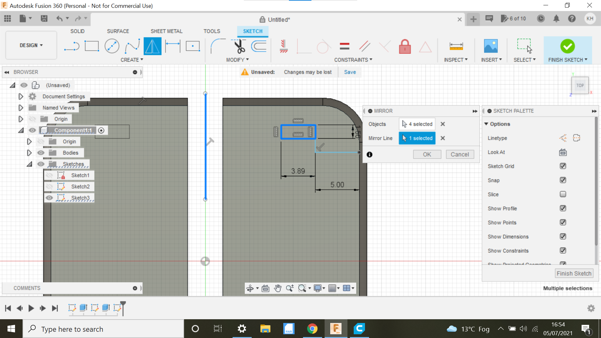
We can now create the 3 Tabs as on the original, starting with the 2 at the top of the insert.
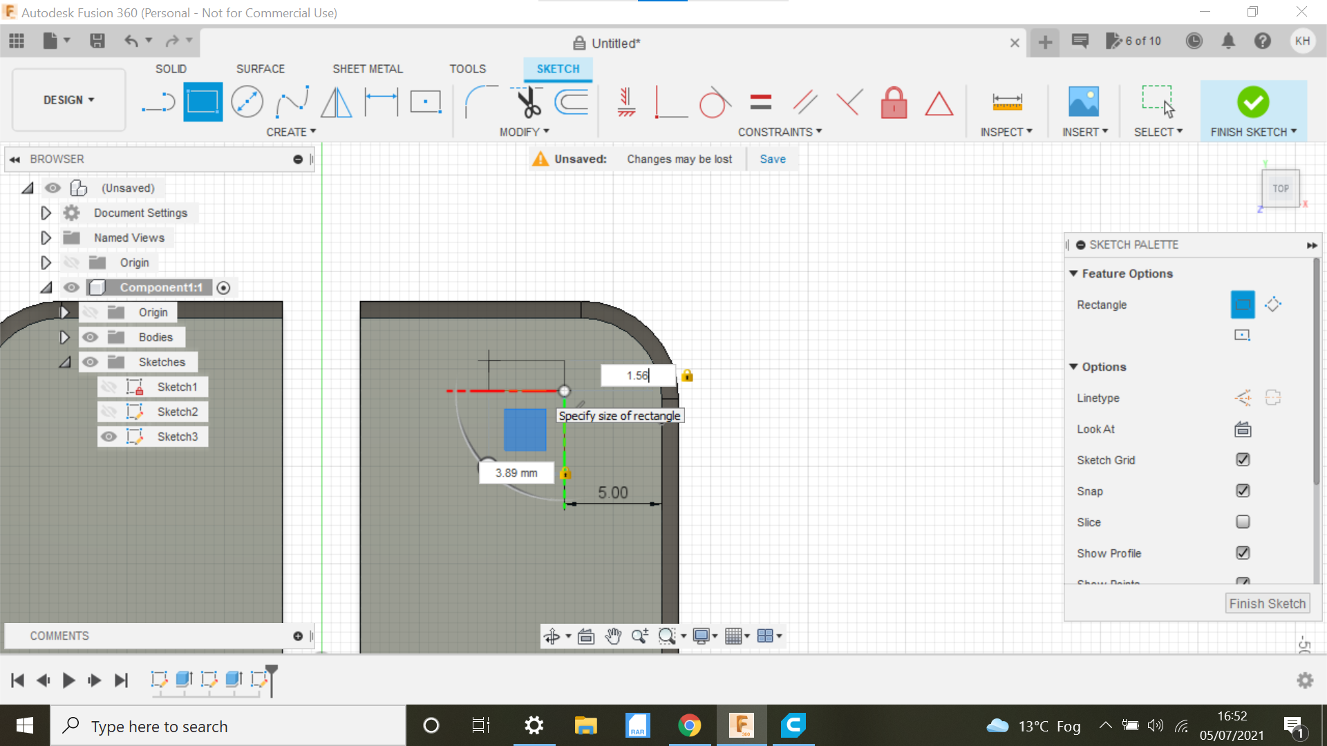
The first tab is created picking the top face of the insert, the Tab is 5mm inboard for the the drafted edge and 1.81mm inboard form the top of the drafted edge, the tab can now be extrude to 4.5mm, there is a lip on each tab of approx 1mm, mirror this tab selecting all faces of the tab and then select the middle place, we can now take the dimensions for the 3rd and final tab, the tab is Identical to the first 2 same distances and on the centre line making things easier.
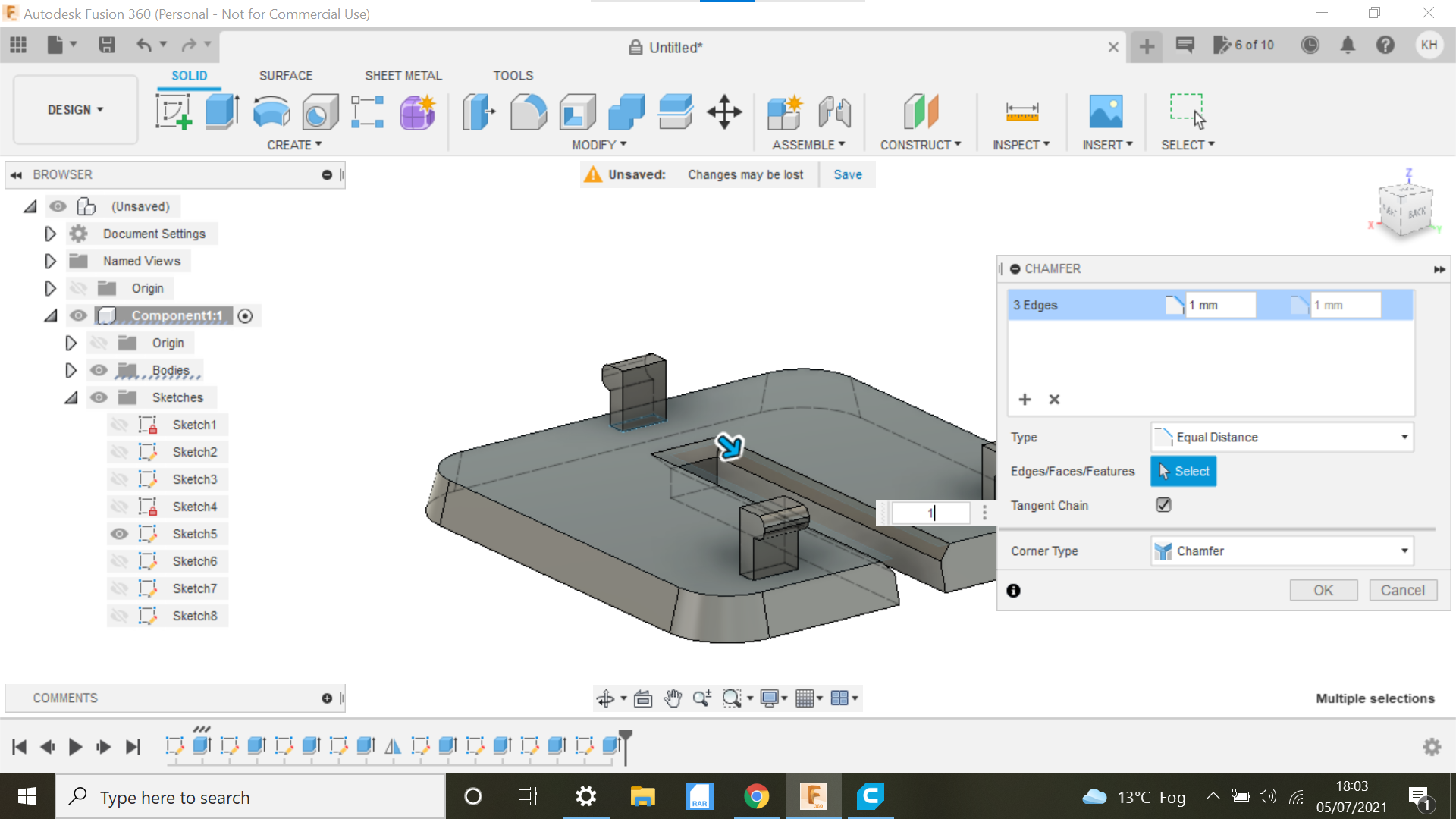
We can now select the chamfer Tab and select each line of the 4mm rectangle and chamfer 1mm, not sure why, the original has a chamfer.
The protrusion on the Tabs has rounded edges, lets do this just for the benefit of this Instructable.
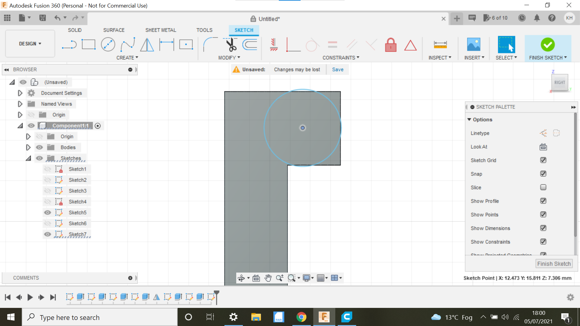
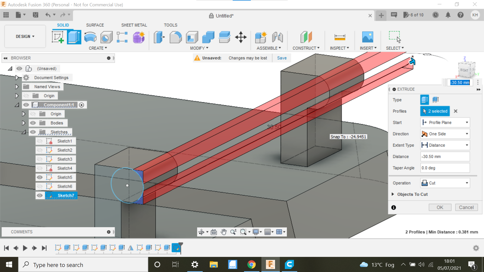
If we start with the 2 top tabs first, select one of the edges as our face, and create s centre circle allowing us to extrude the corners of the tab, selecting cut will allow us to do both of theses tabs as they are mirrored and identical, the same applies to the remaining tab.
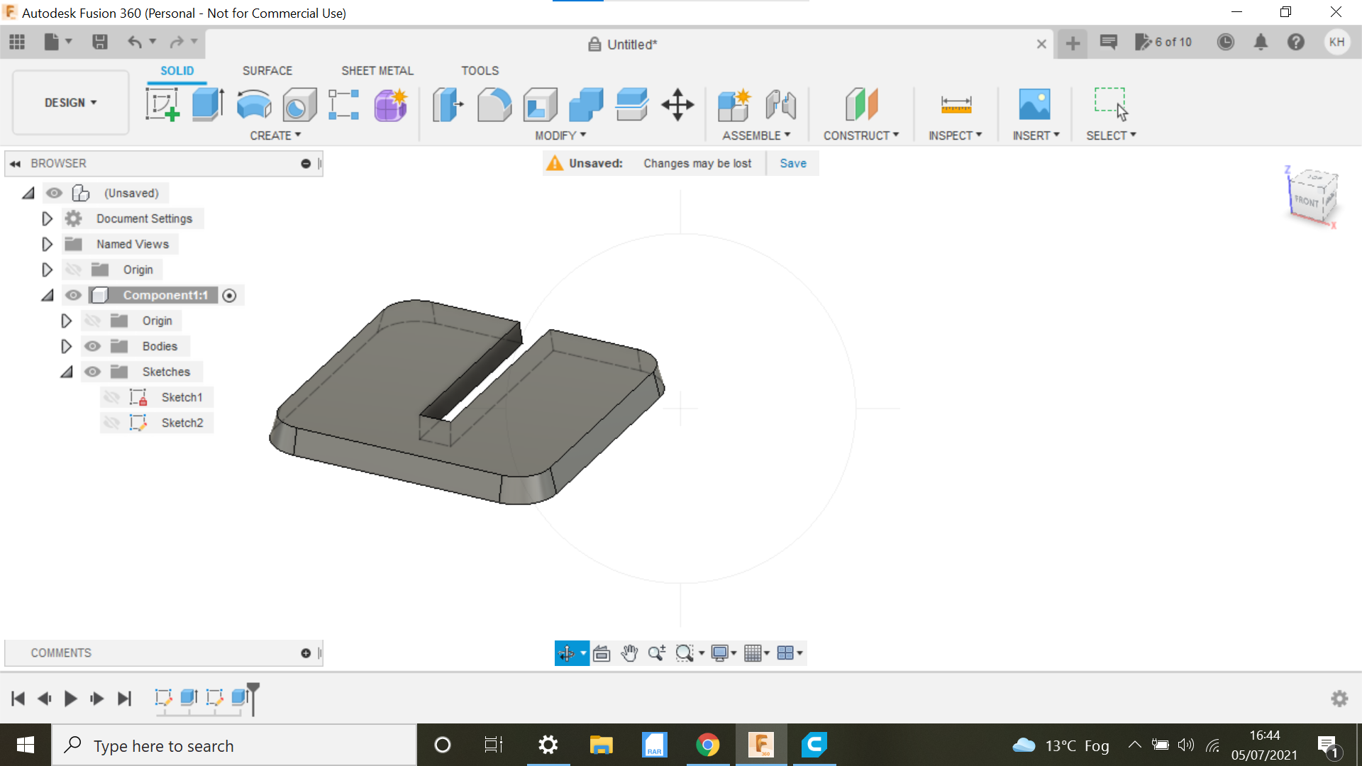
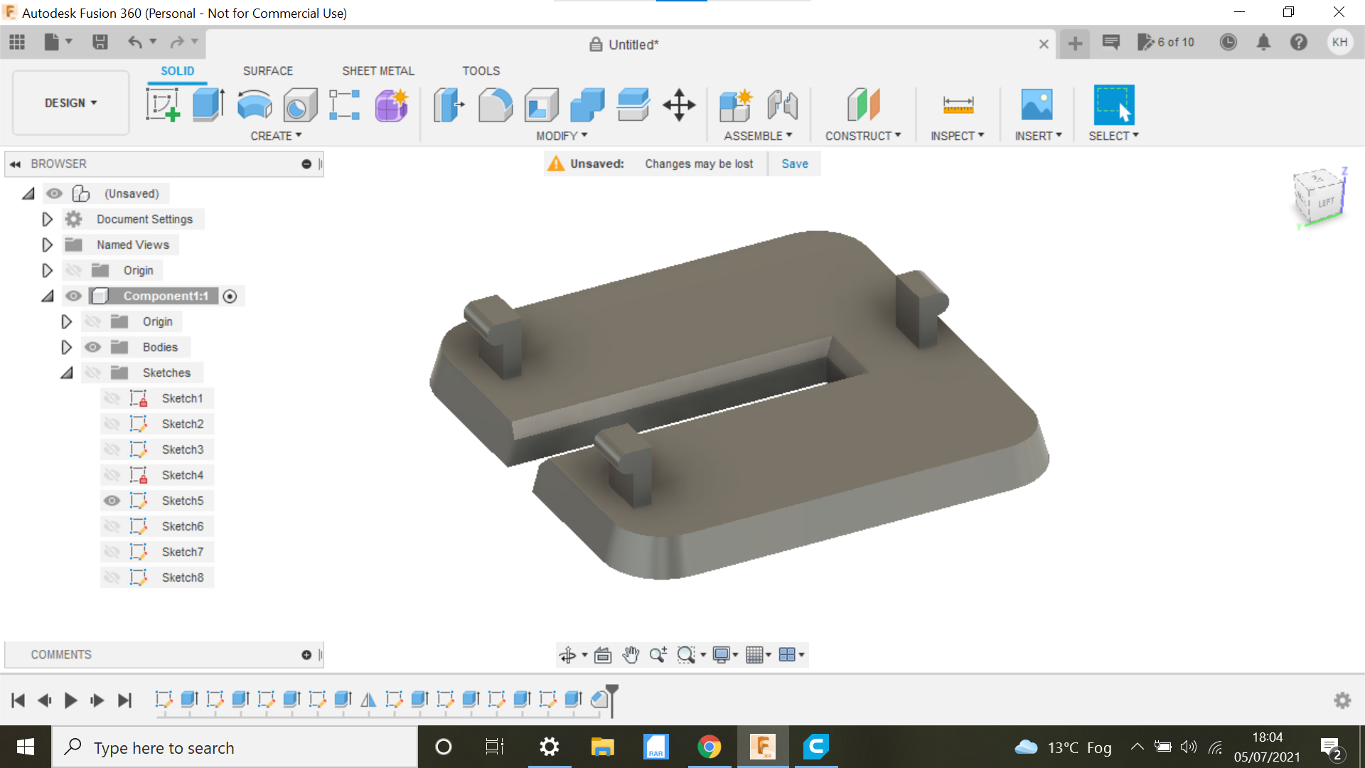
That's it for the design sketch and extrusion.
Lets move onto printing the prototype.
3D Printing the Bandsaw Table Insert.
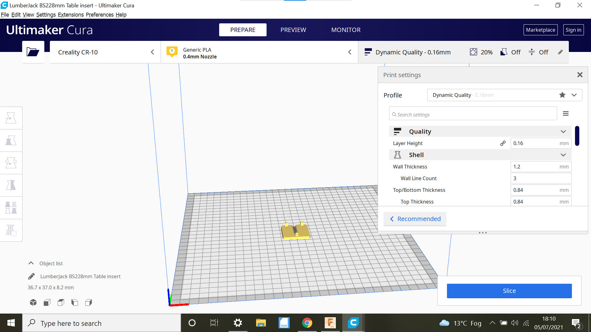
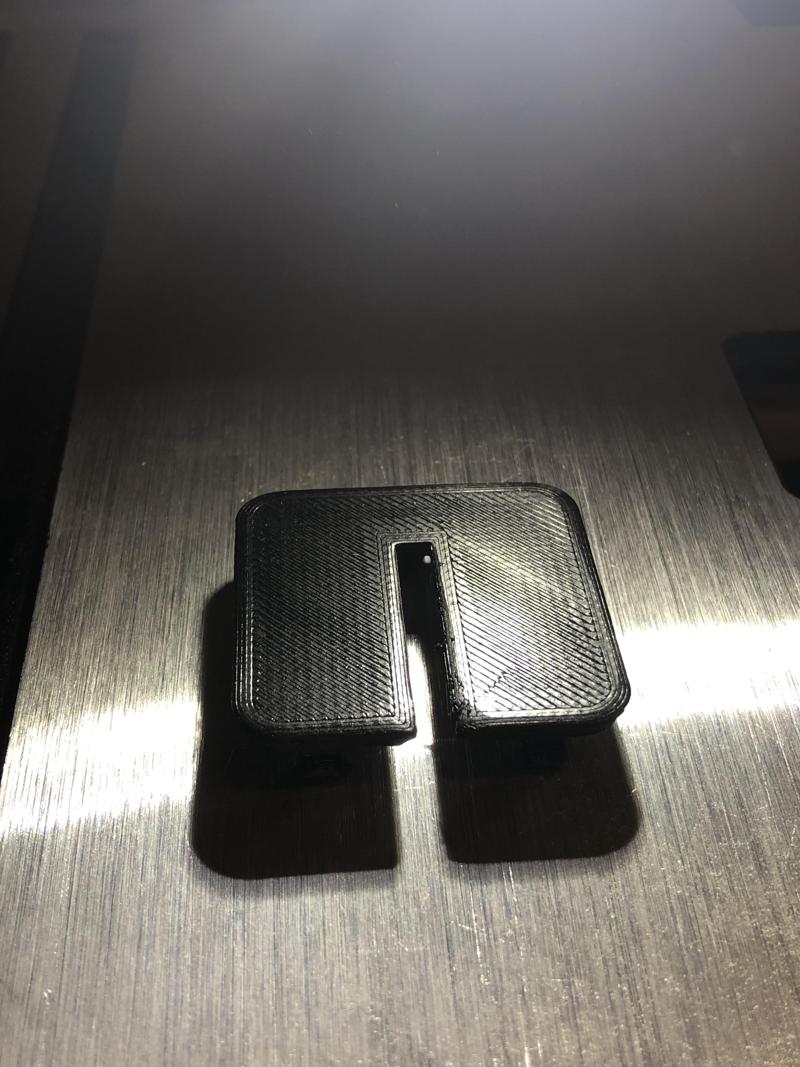
With these small components I have been using High refinement when selecting the 3D print option with Fusion 360, this in conjunction with using the dynamic option in Cura is producing some quality small components even just using 20% infill, I am also using Gyroid as the infill pattern, no supports needed in this case.
Its a 35 minute print, if its too high just flip the insert in Fusion 360 and -extrude to what ever depth makes it flush with table.
I always end up doing a couple of prototypes before reaching the final part, we are DIY/Hobbyist's after all its cool, and PLA is relatively cheap in the bigger scheme of things anyway.
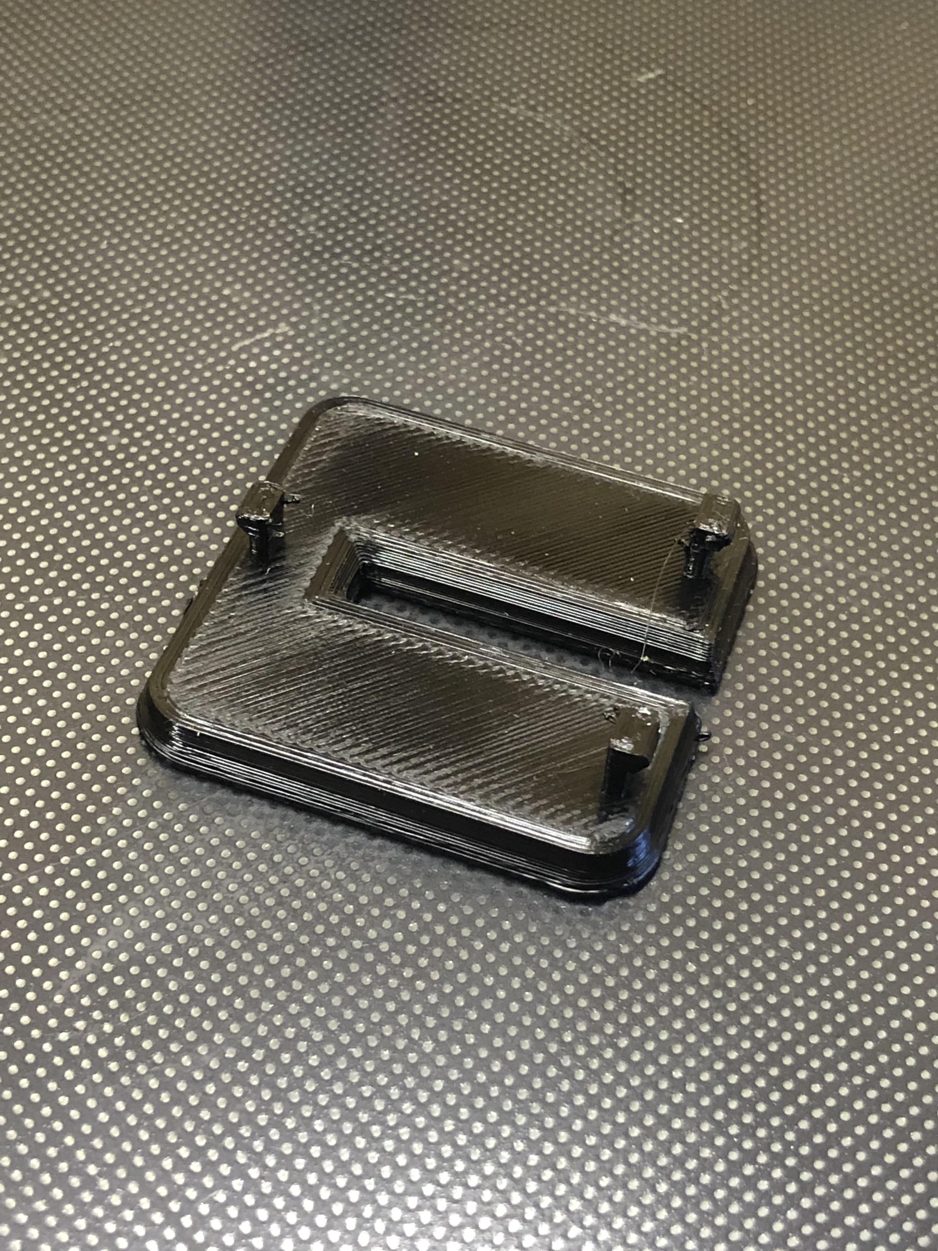
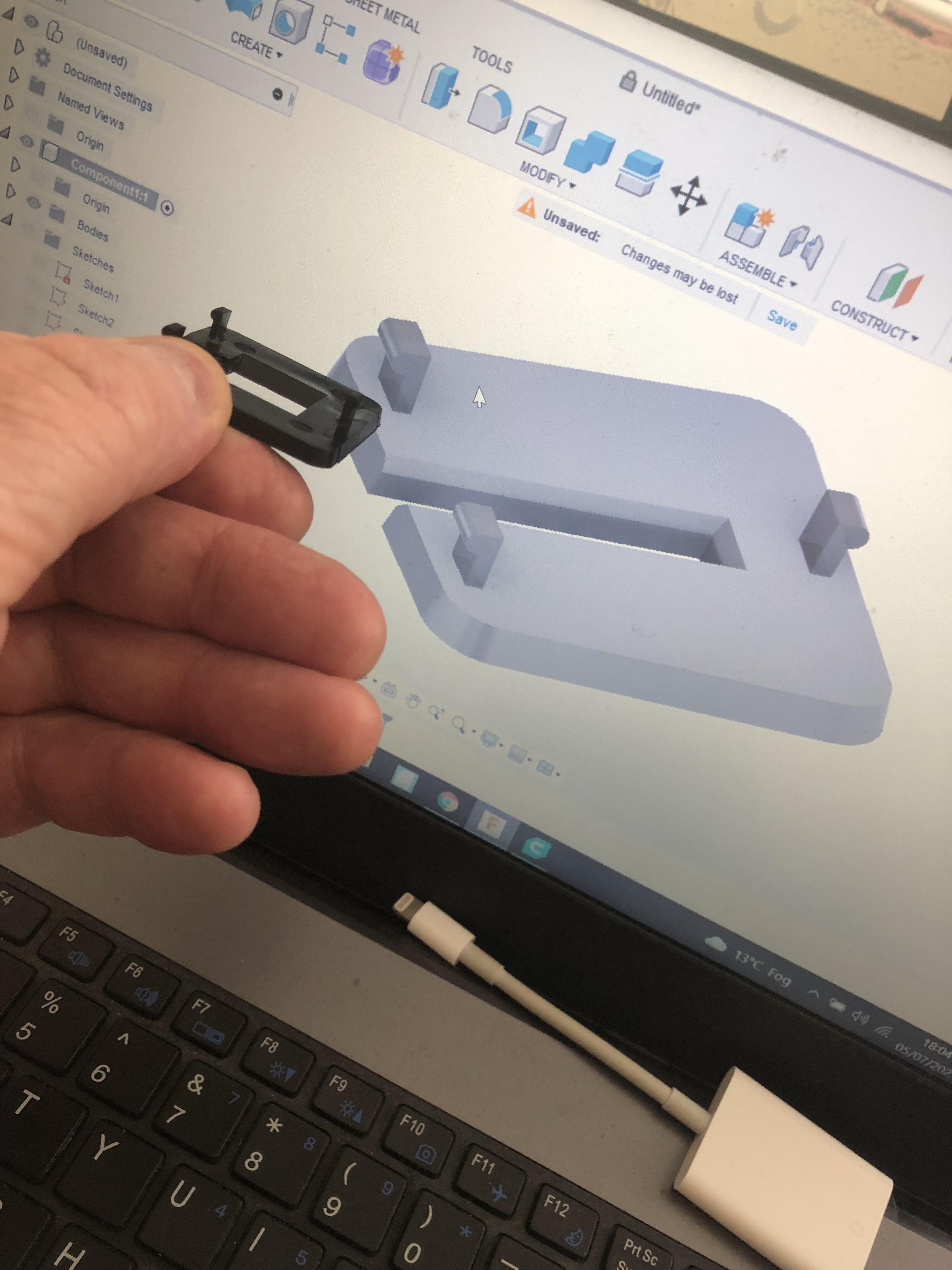
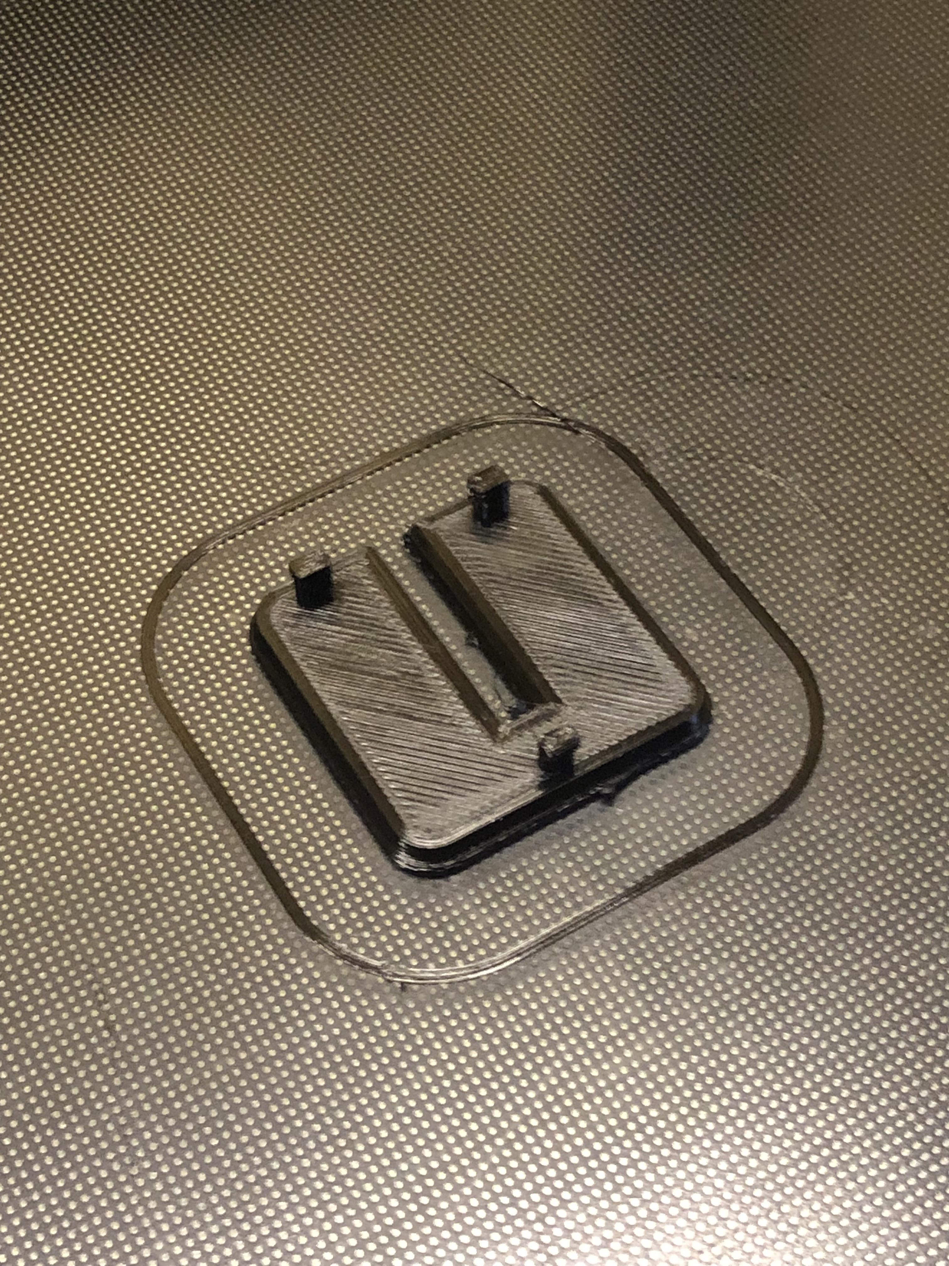
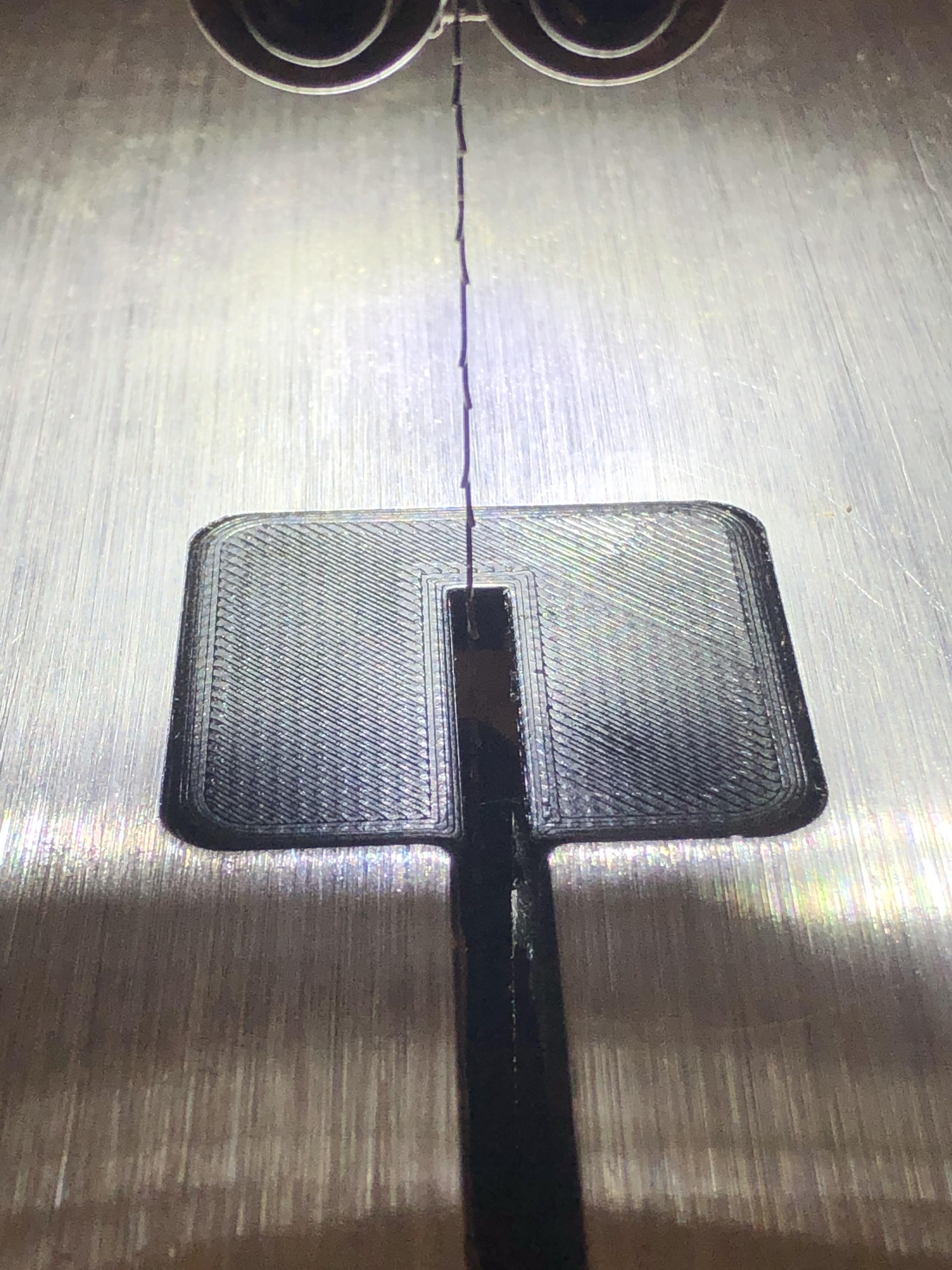
The first insert was too shallow of all things but a perfect fit in the recess which was good so I flipped the design and extruded to what should be the end result, but the finished part looked amazing.
With the new Insert and a new premium blade this bandsaw is different again so its not destined for the scrap bin just yet.
I've added the Cura 3D print file for anyone who has the same machine.
As always, I hope you enjoyed this Instructable and got a few basic pointers with Fusion 360, what a fantastic platform allowing us Hobbyists to design and create things like this, Awesome!