BOSEBerry Pi Internet Radio
by BlackberryJamMan in Circuits > Raspberry Pi
5832 Views, 45 Favorites, 0 Comments
BOSEBerry Pi Internet Radio
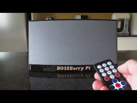
I love listening to the radio! I was using a DAB radio in my house, but found the reception was a bit patchy and the sound kept breaking up, so I decided to build my own internet radio. I have a strong wifi signal around my house and the digital broadcast should mean that I was able to play high fidelity sound.
I didn't want to use a smart speaker. I wanted to switch the radio on, be able to change channels and then switch it off, so it behaved just like a traditional radio but as it was using the internet for its connectivity, I could listen to radio channels from anywhere in the world.
I managed to find a second hand BOSE SoundDock series II model on ebay (cost £5.33) but it was listed as not working. This wasn't a problem as I would remove all the internal circuitry to add my own.
Supplies
A Bose SoundDock (I used the series II model)
Raspberry Pi Zero Wireless with right angle GPIO header pins
DAC decoder PCM5102A
Amplifier PAM8403
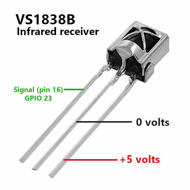
VS1838B infrared receiver
HX1838 remote control
Barrel jack 2.1mm socket
Connecting wire (I used wirewrap)
3D printing facilities
Spool of PLA printer filament
Acrylic lacquer spray
Enamel paint
M3 nuts
M3 x 8mm dome head hex drive machine screws
IR receiver LED
Veroboard & header pins
Disassemble the Unit and Clean It
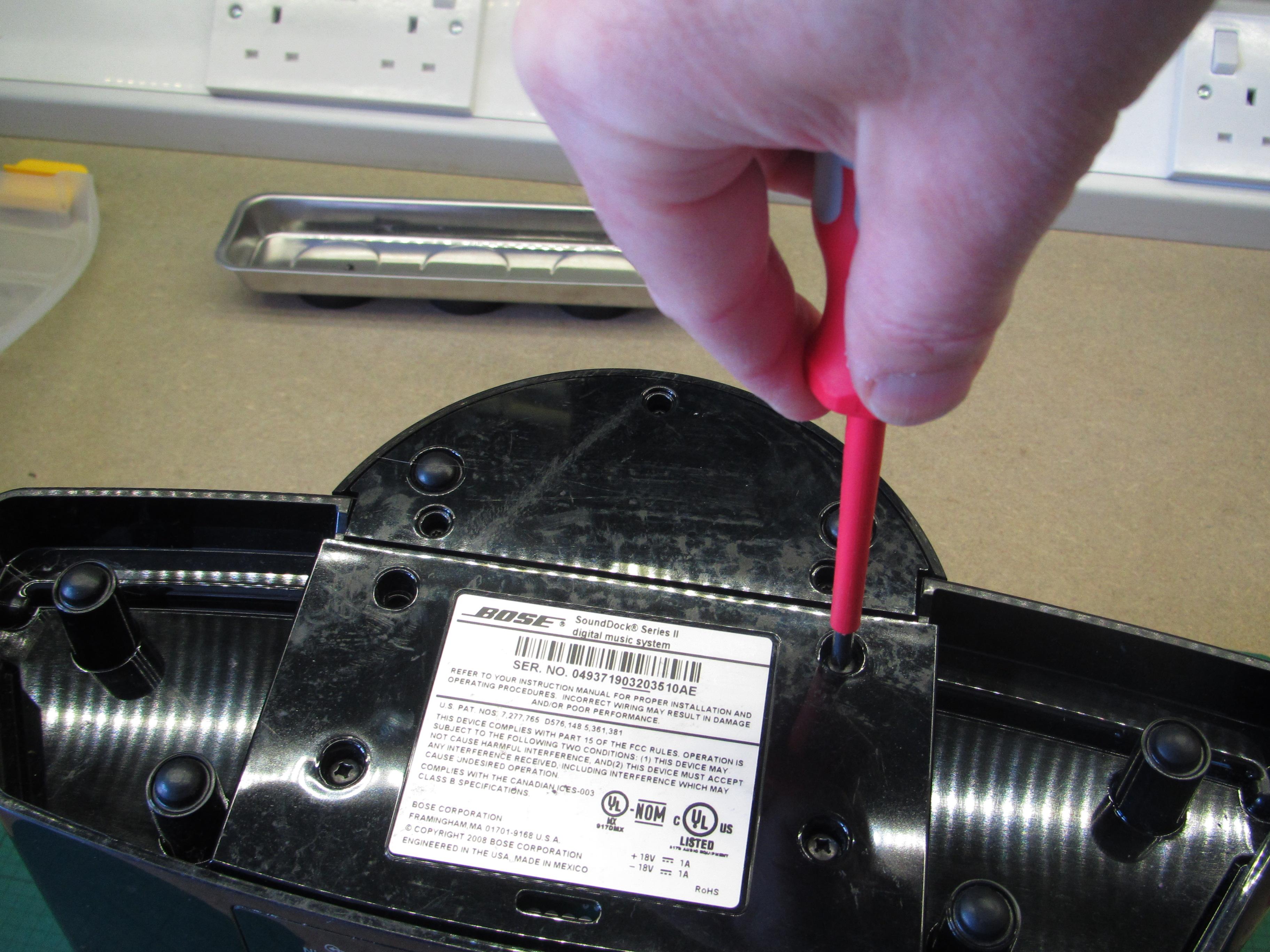
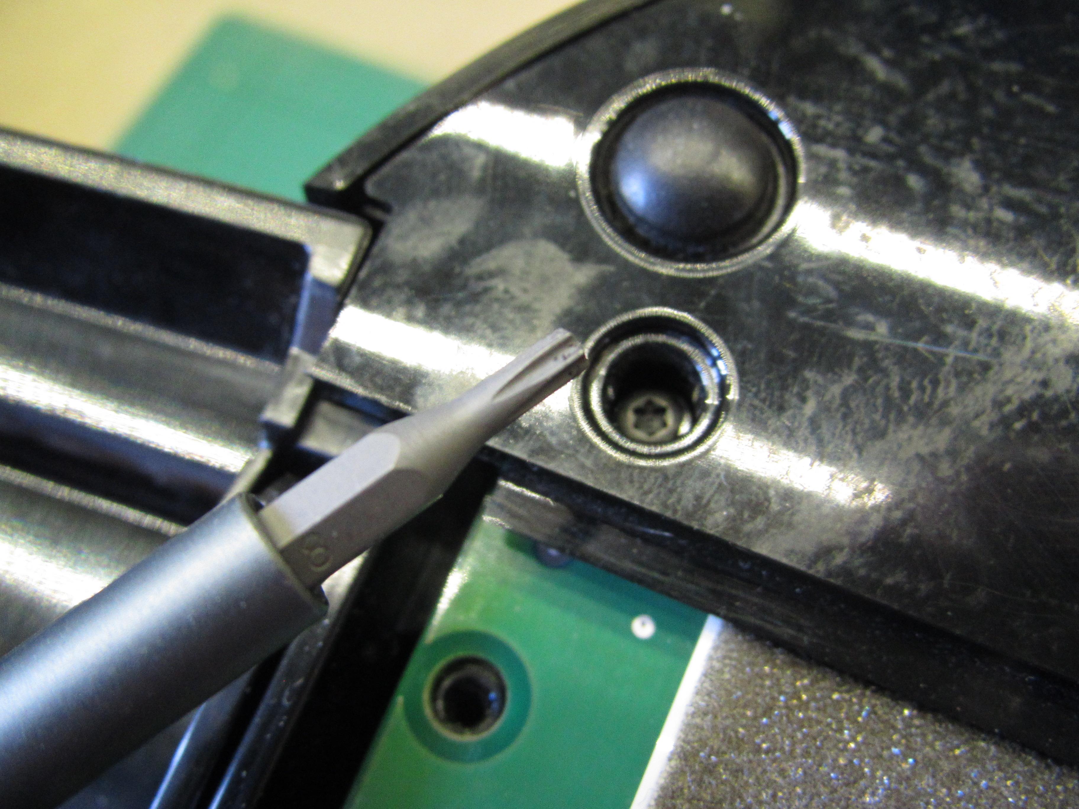
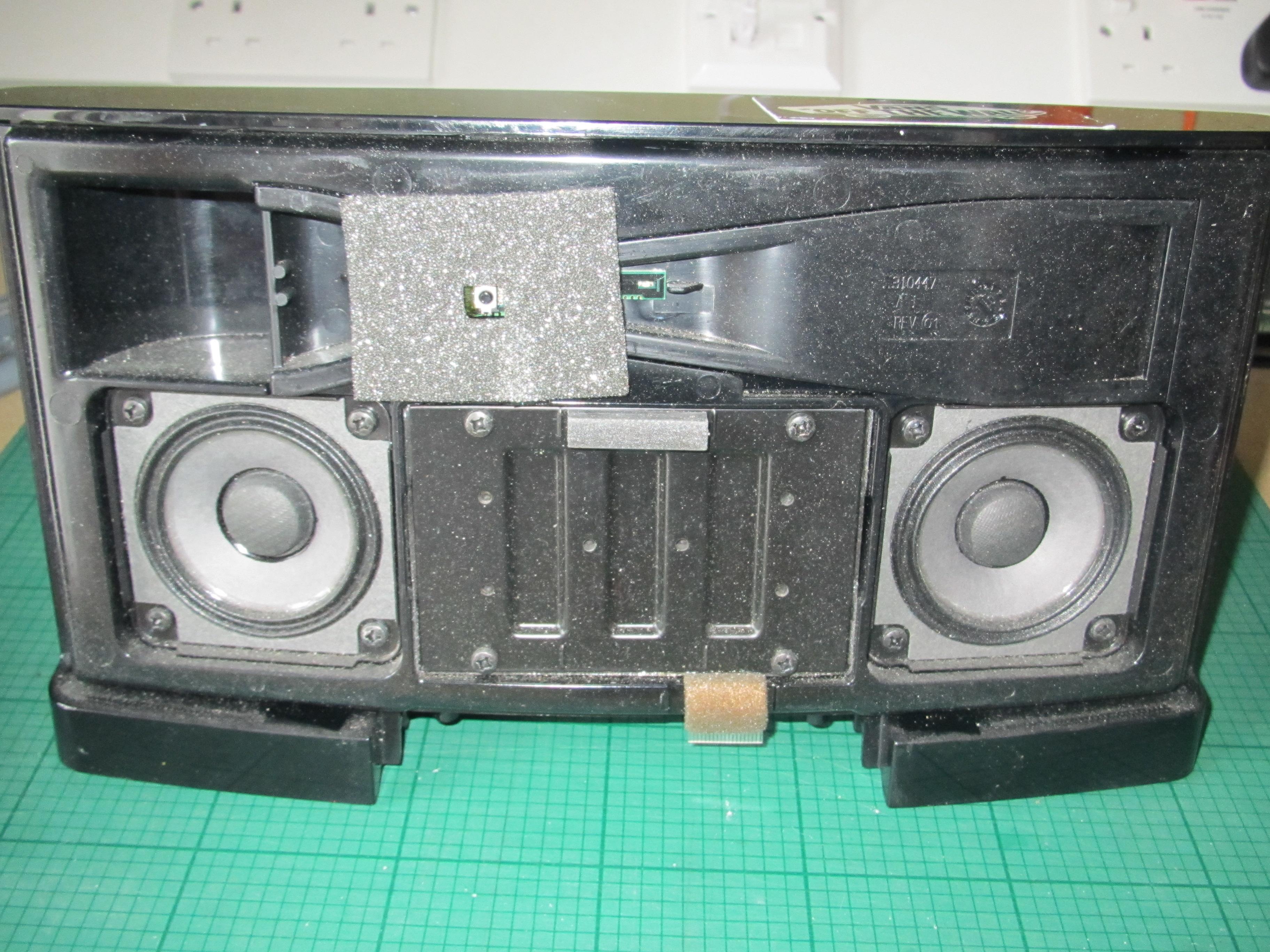
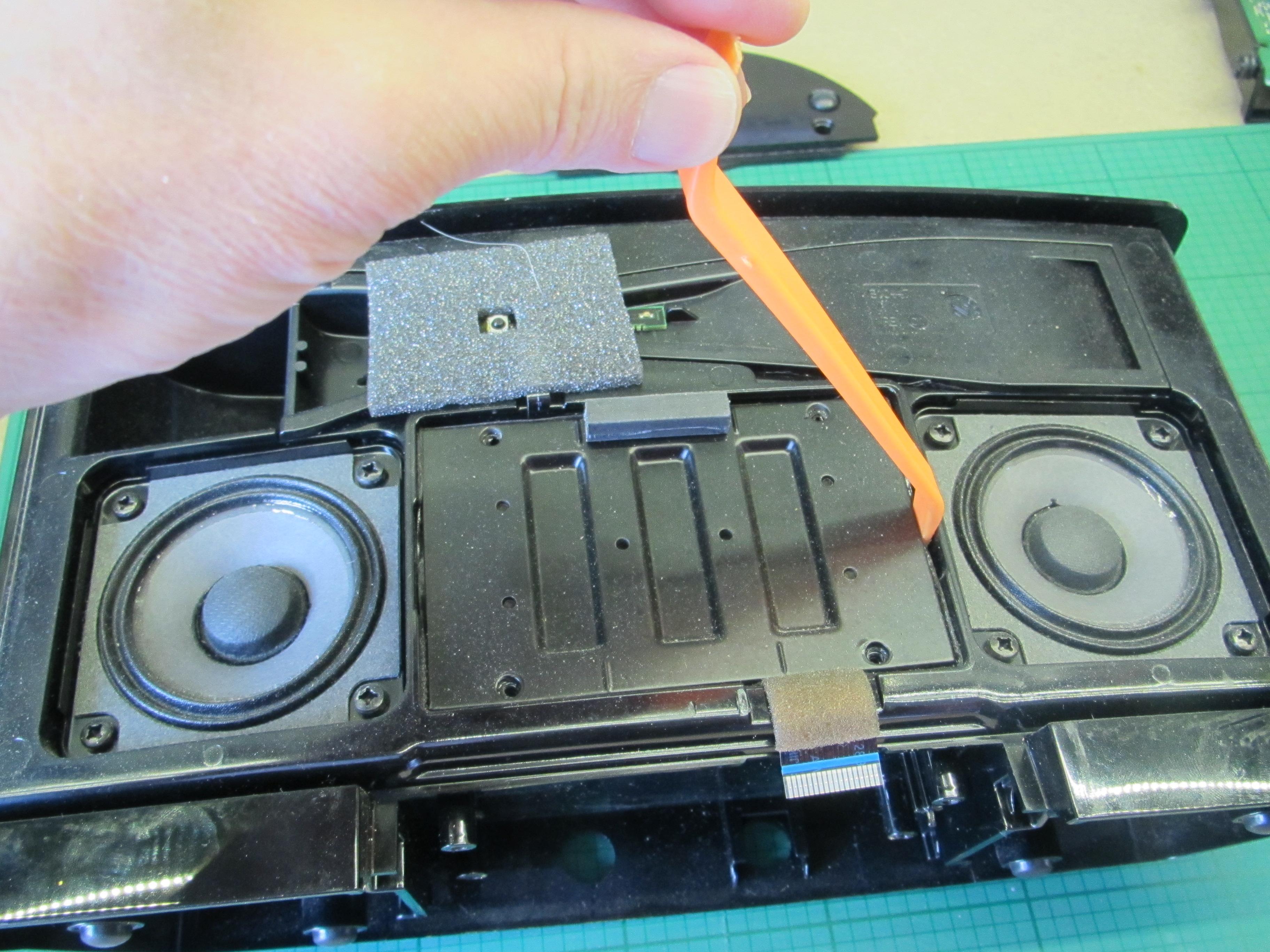
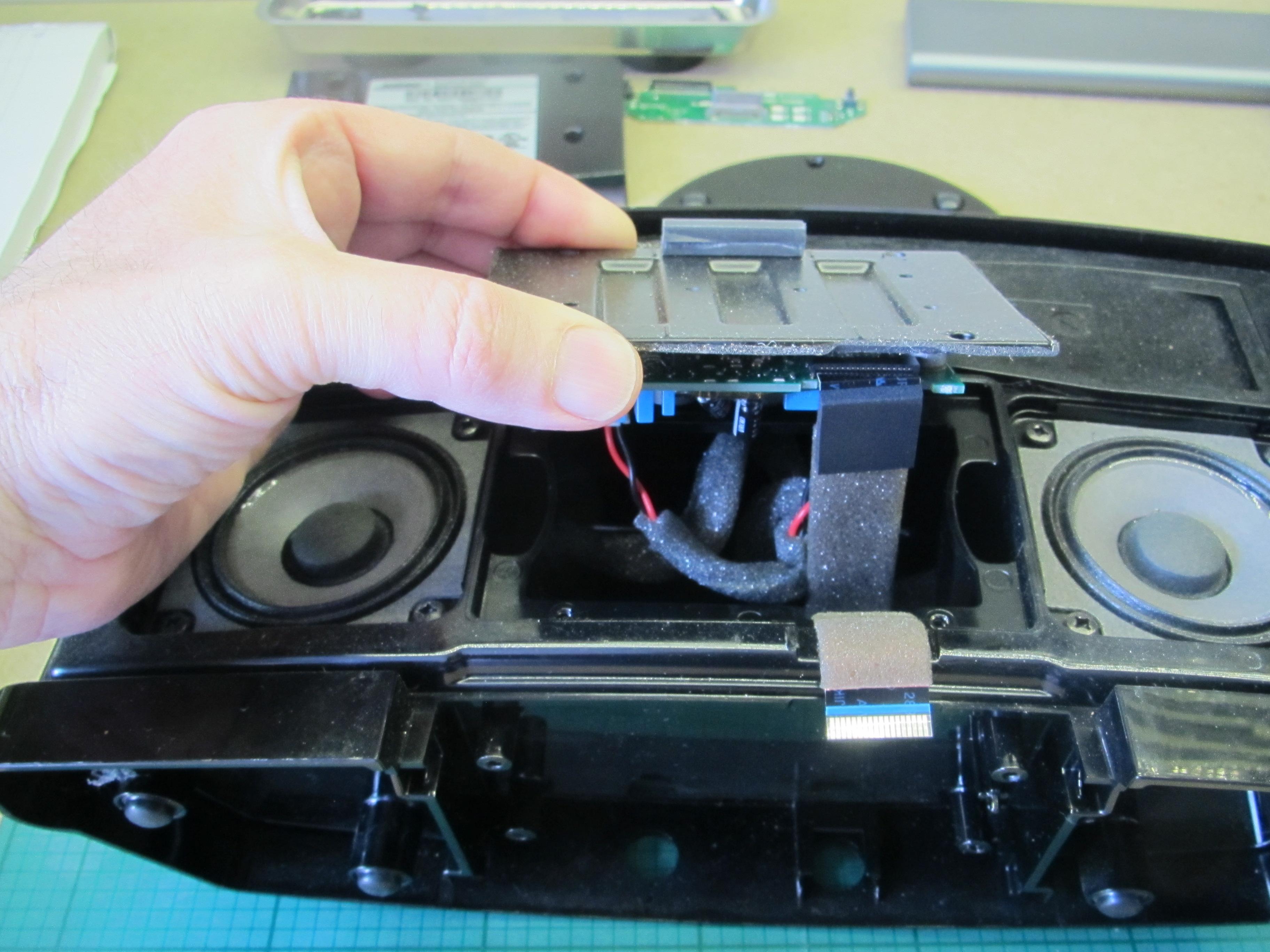
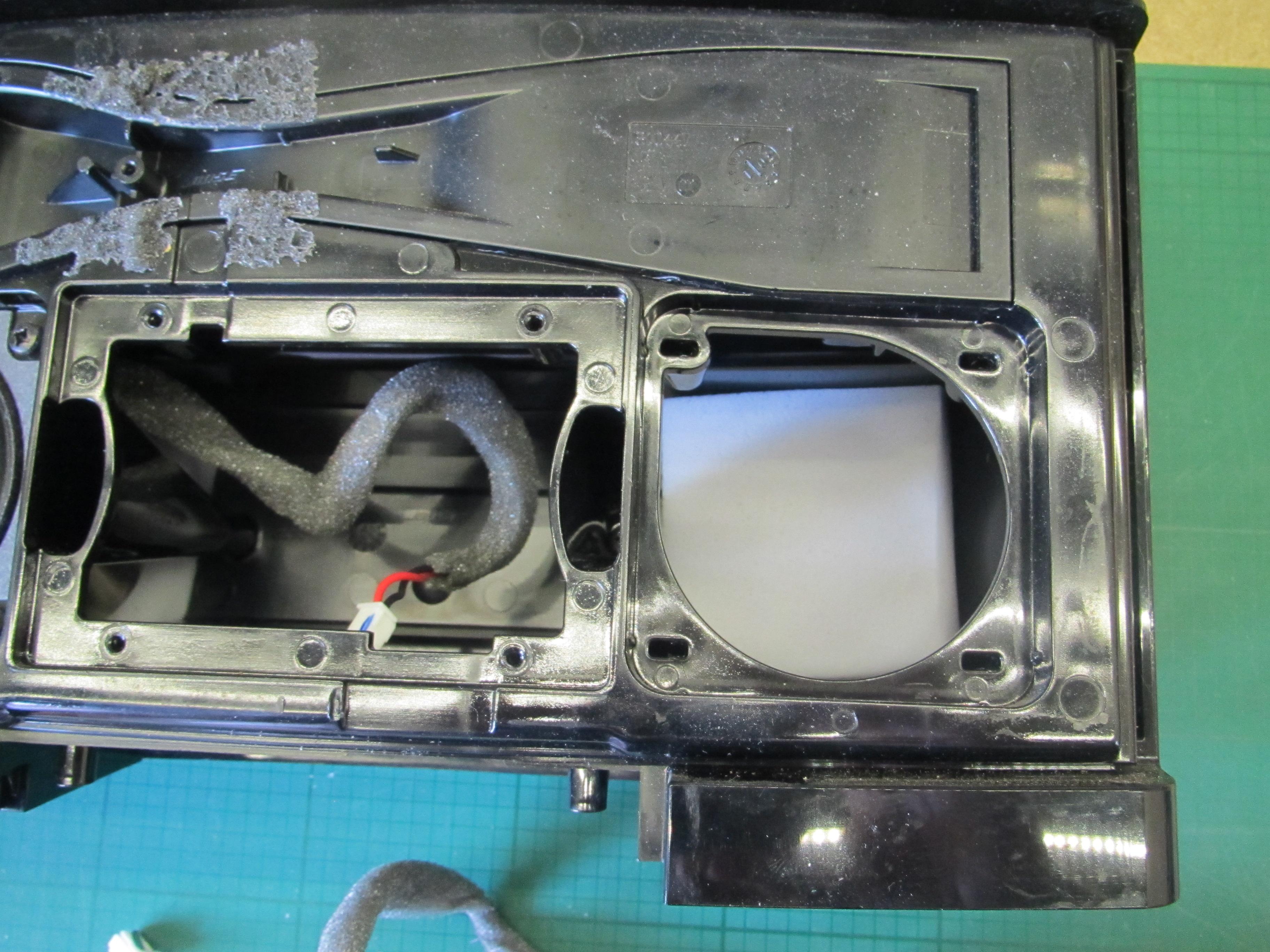
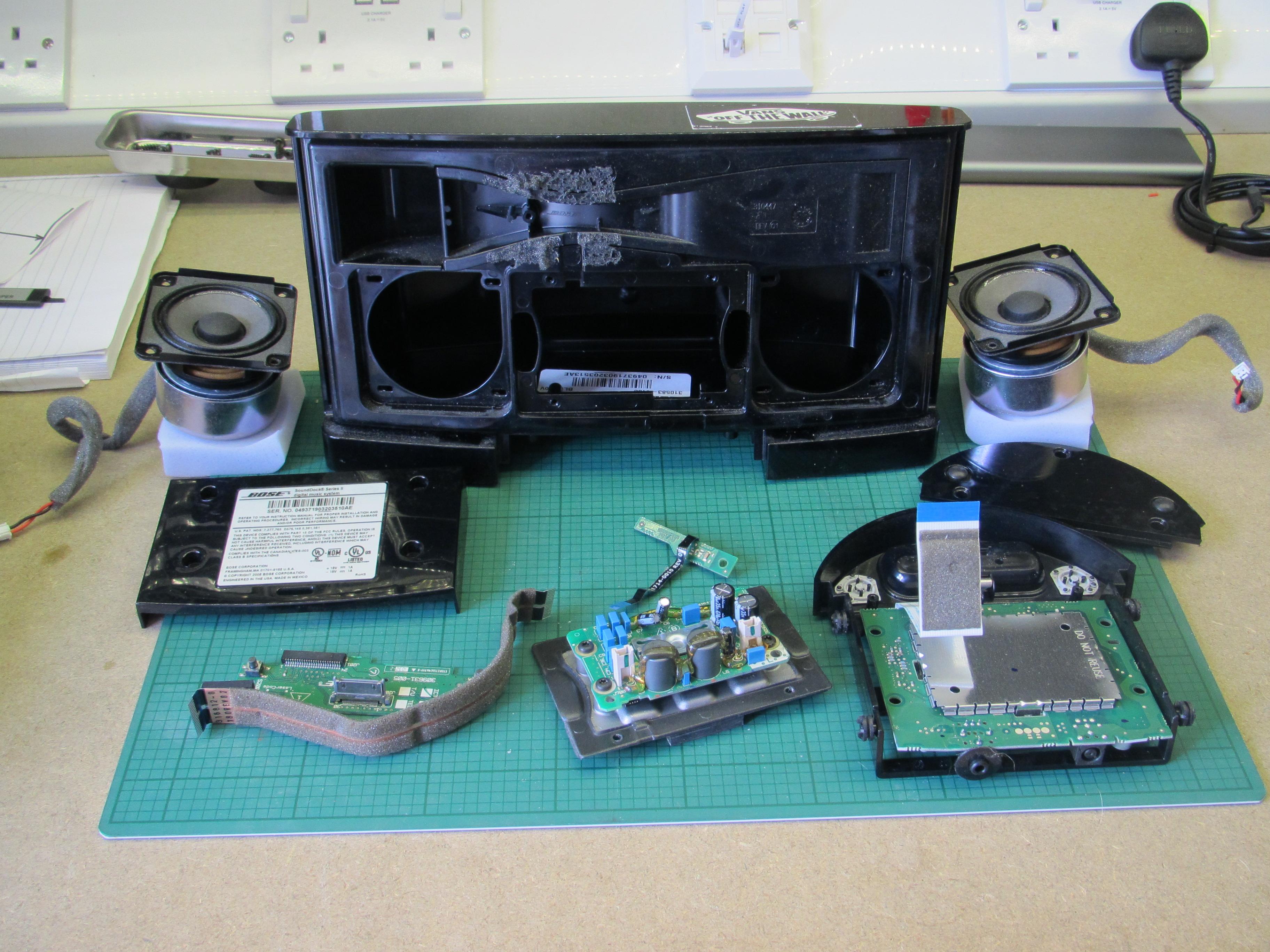
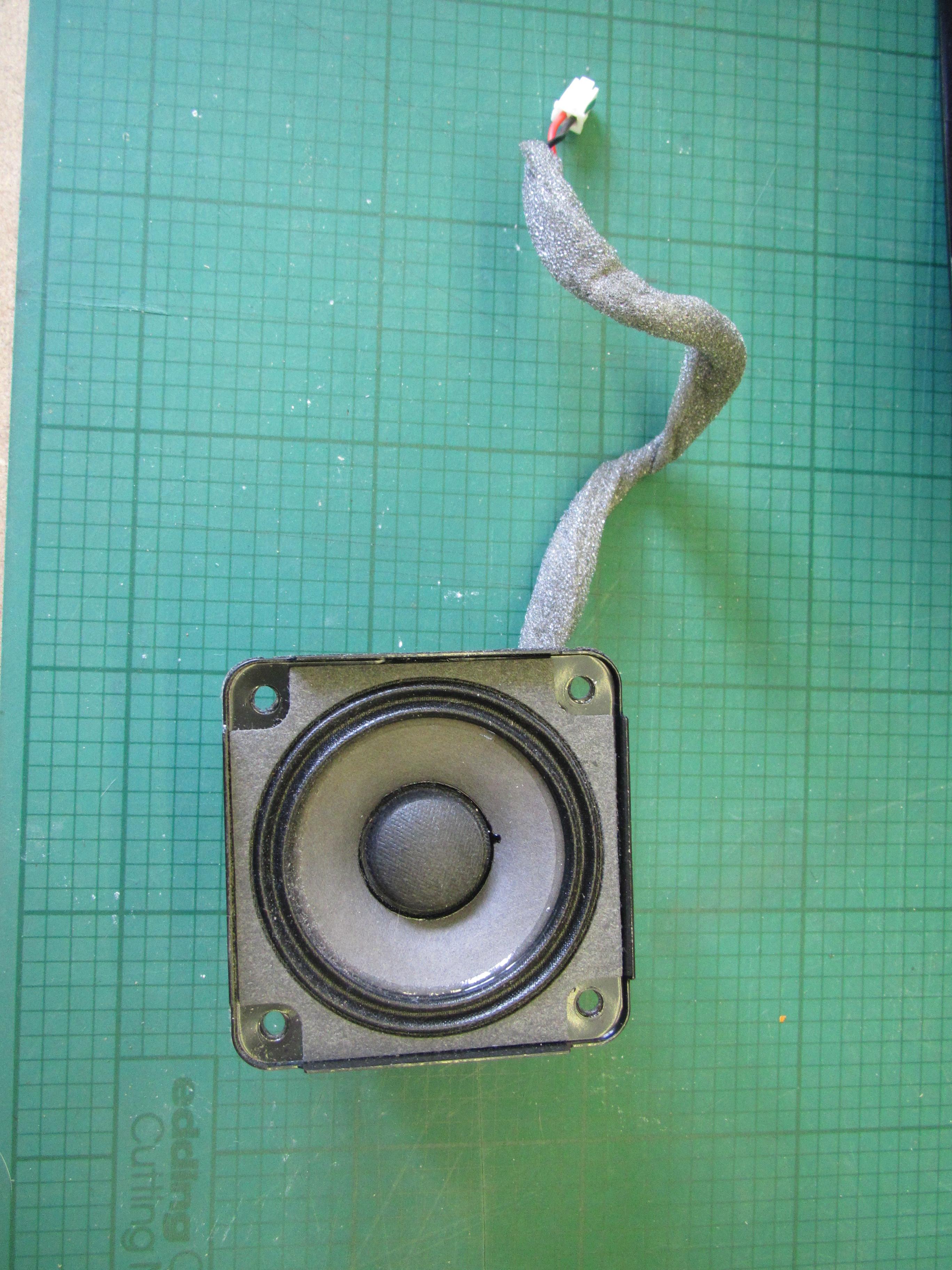
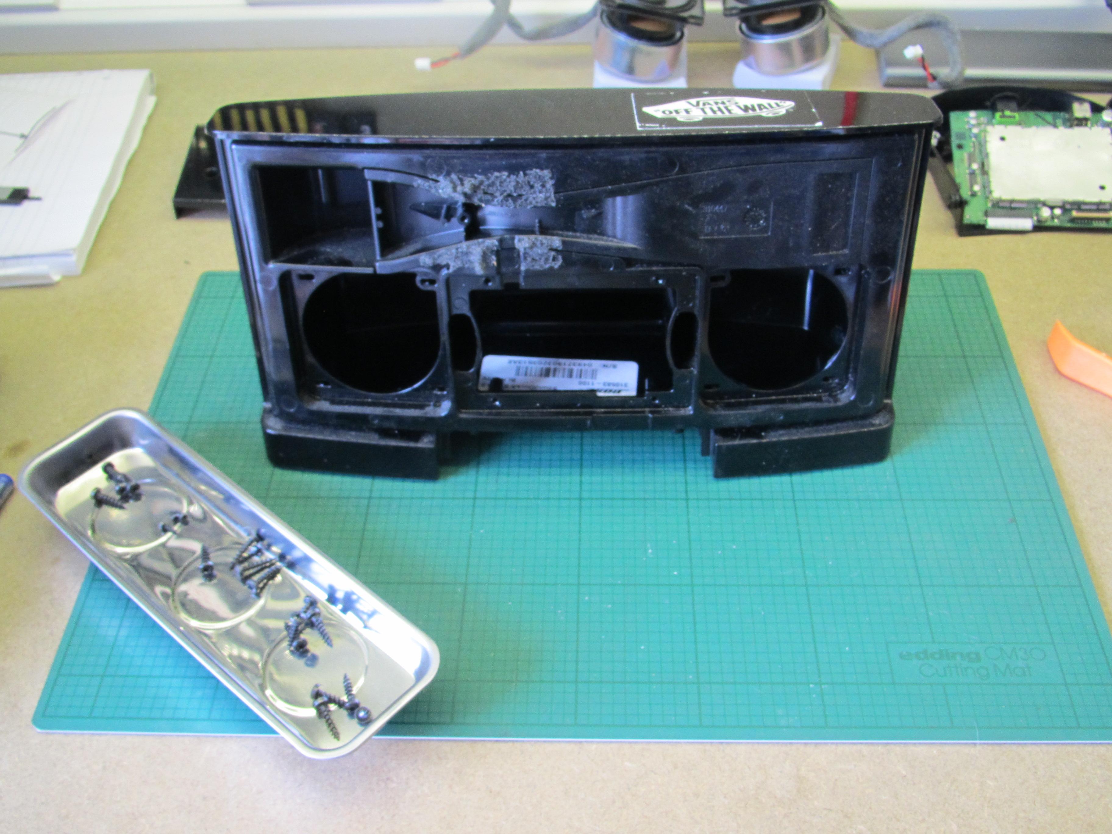
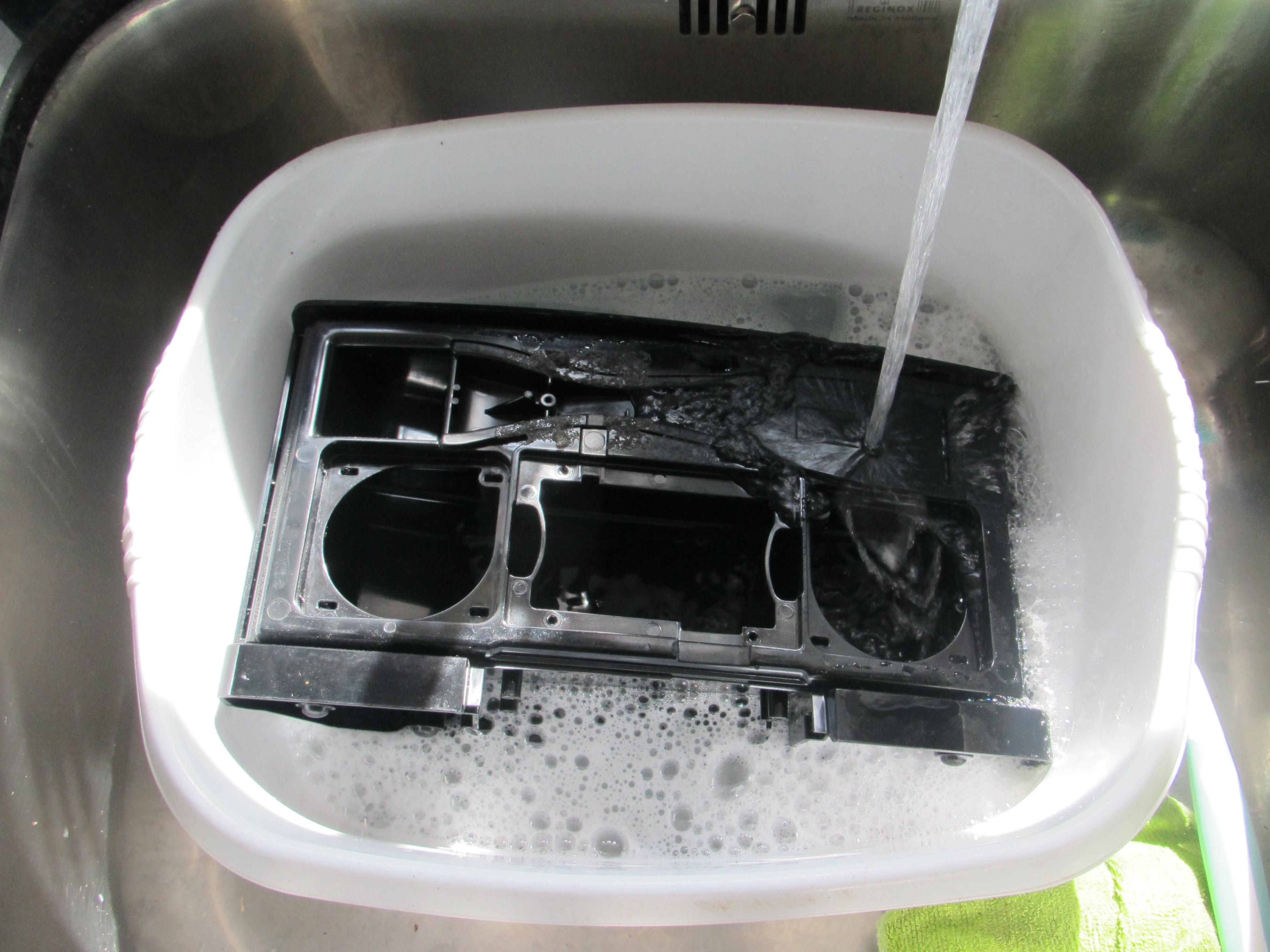
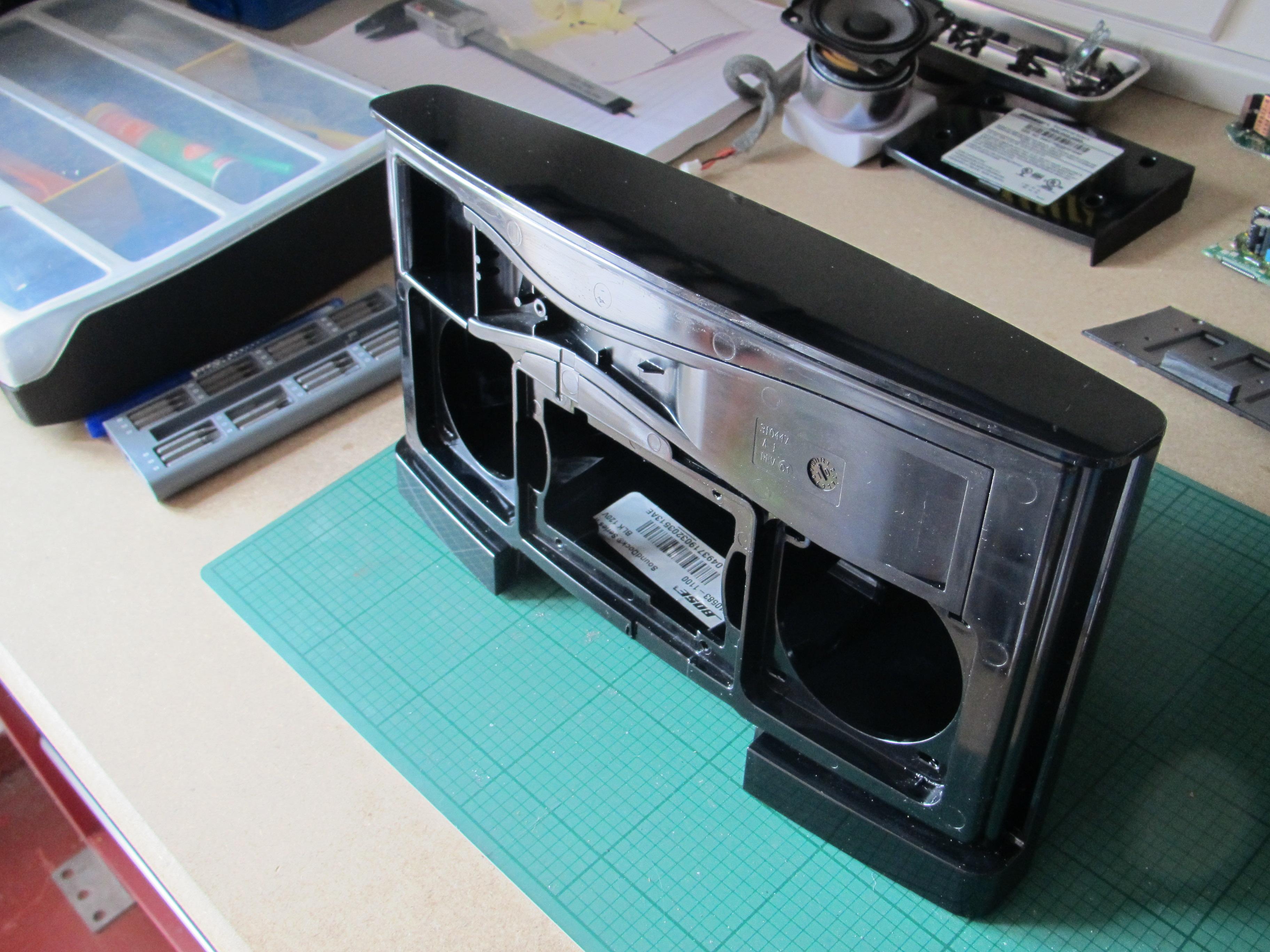
The SoundDock is easy to take apart. Remove the base first and disconnect the wiring loom. The front ipod docking sections uses Torx T6 spline screws.
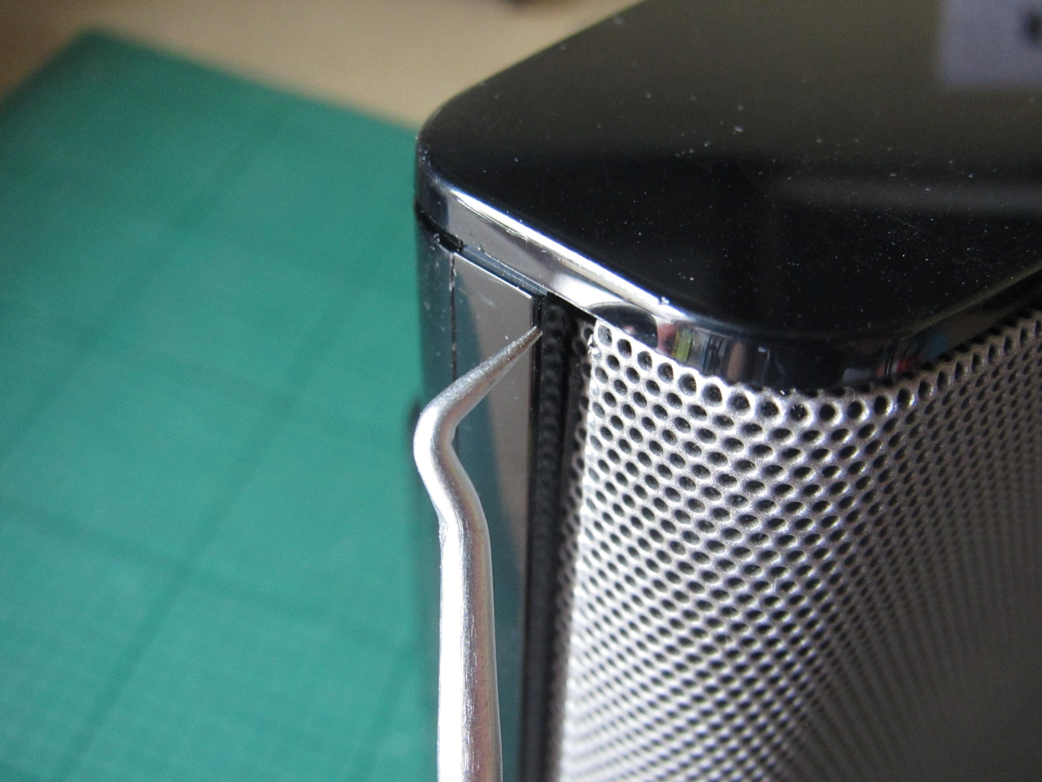
Remove the front wire mesh panel. This is a friction fit that uses foam to grip the side of the case. I managed to loosen it with a hook type pick and then it lifted out easily. I have seen instructions to remove these by twisting a coin in the slot between the wire mesh and the case, but I didn't want to mark the case with the edge of the coin.
The front panel acts as a heatsink for the original amplifier and can be removed with screws. This is then lifted out and the speakers and flat ribbon cable can be disconnected.
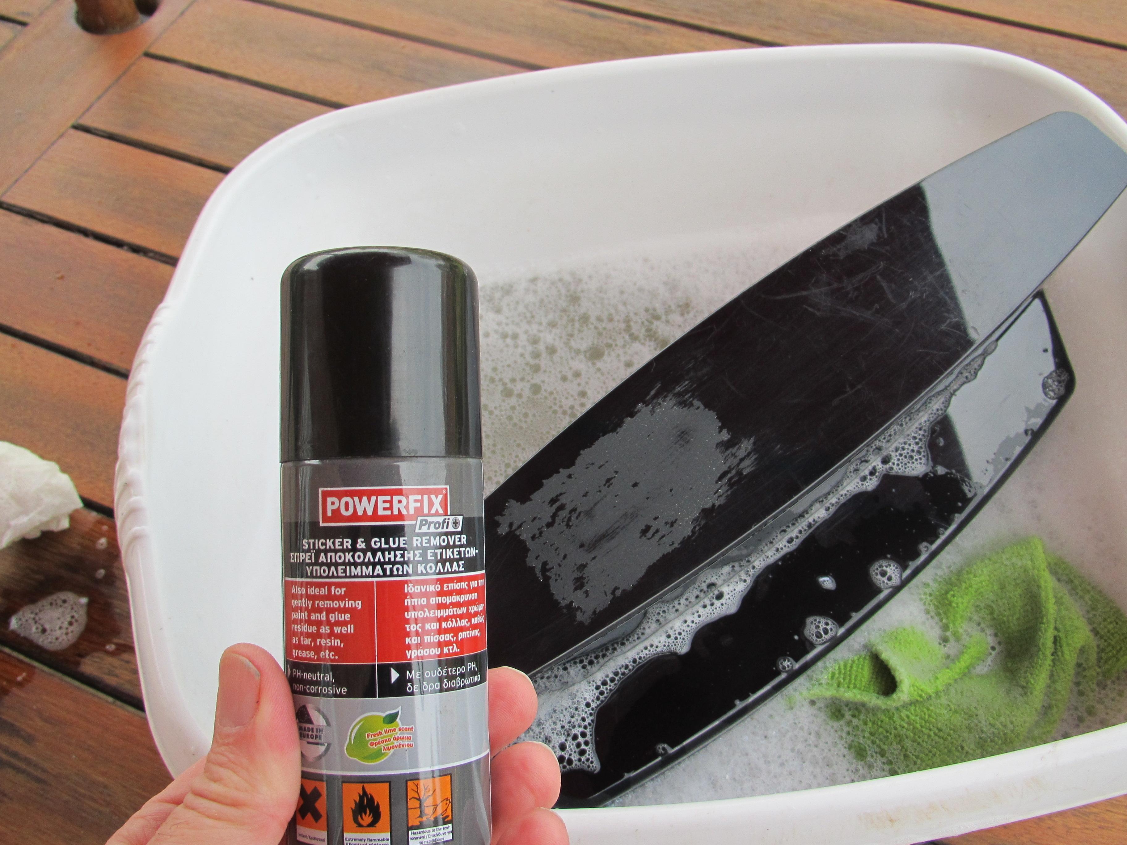
If your SoundDock is an old unit, it has probably picked up a lot of dust and grime. With all the electrical components removed, you can now give it a good clean in hot soapy water. I used a 'sticker remover' spray to clean up the mess left by a label. Remember not to use any abrasive cleaning materials, so you can preserve the high gloss finish on the case.
3D Print the Components
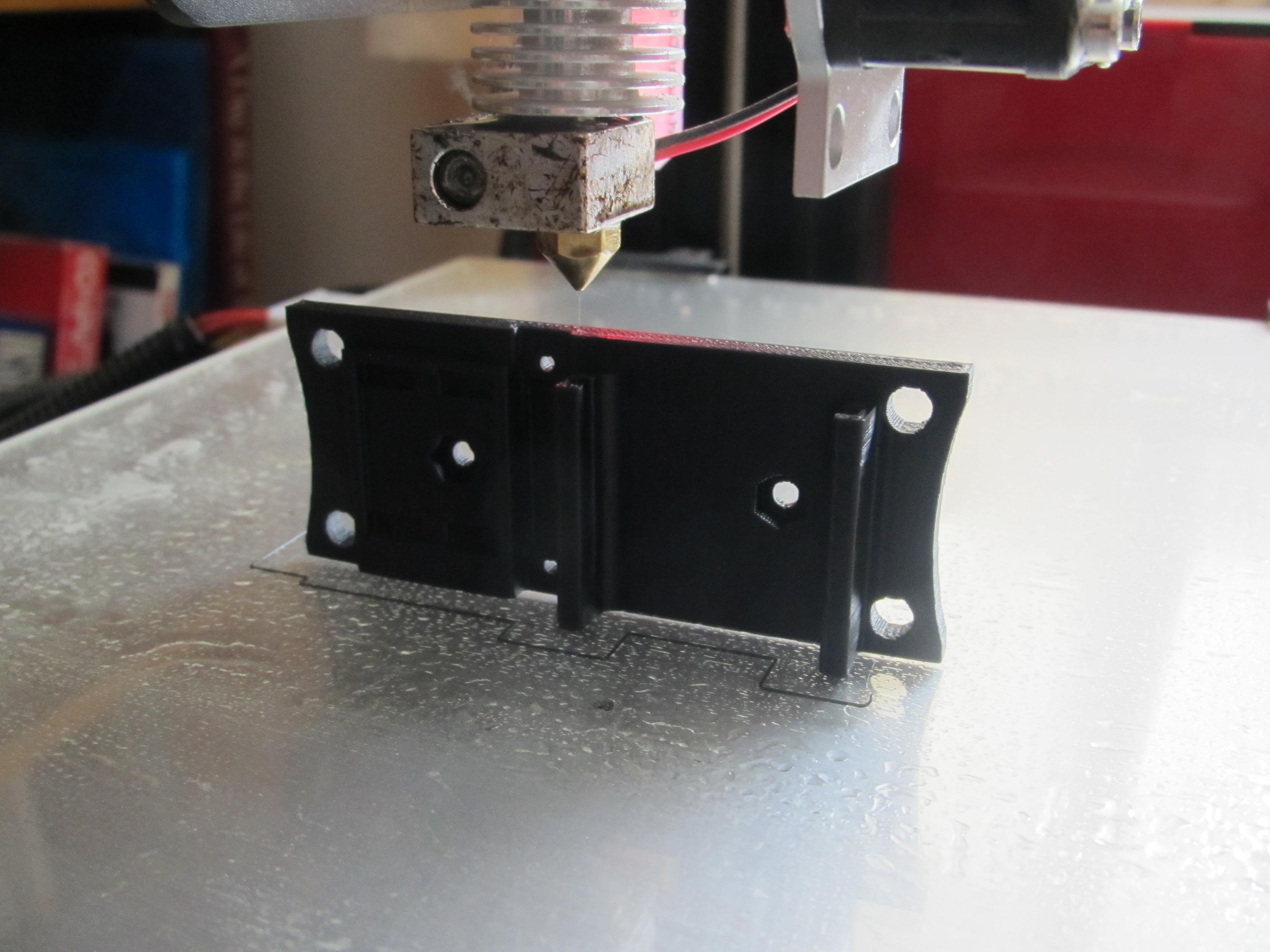
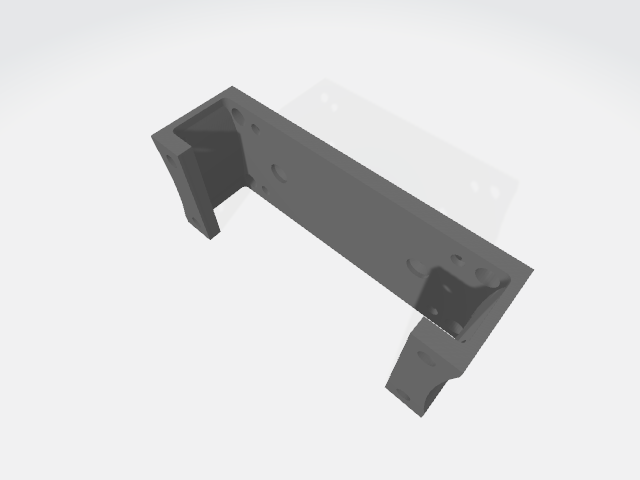
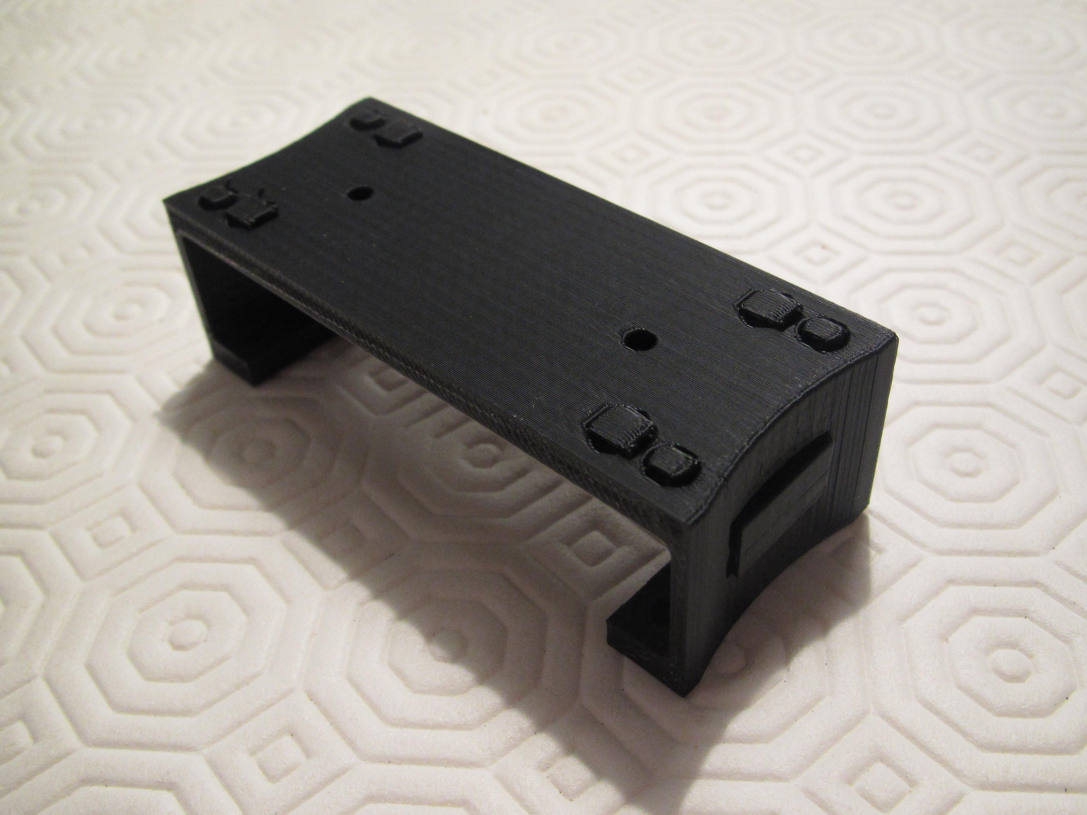
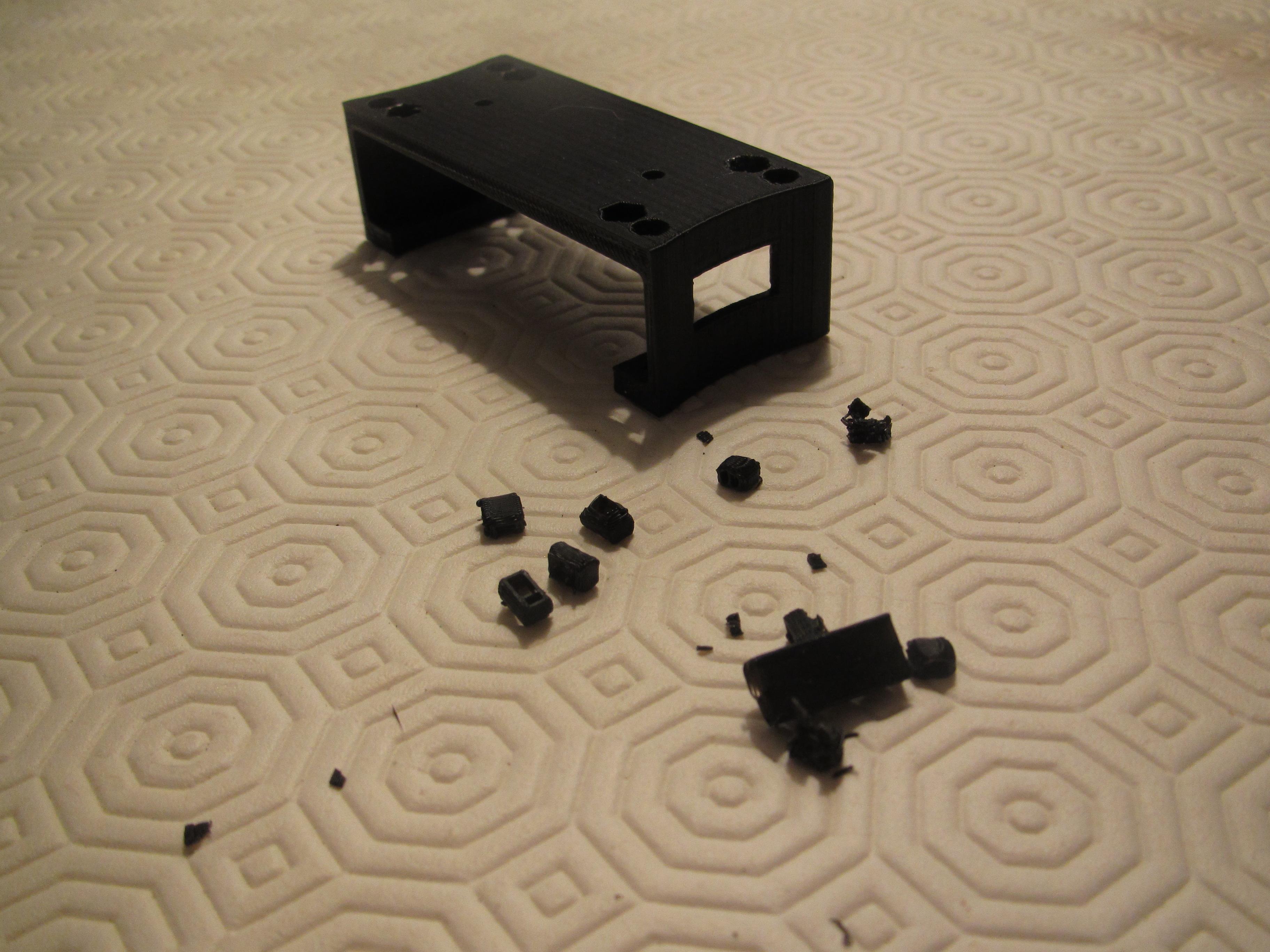
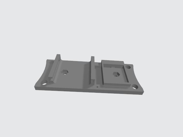
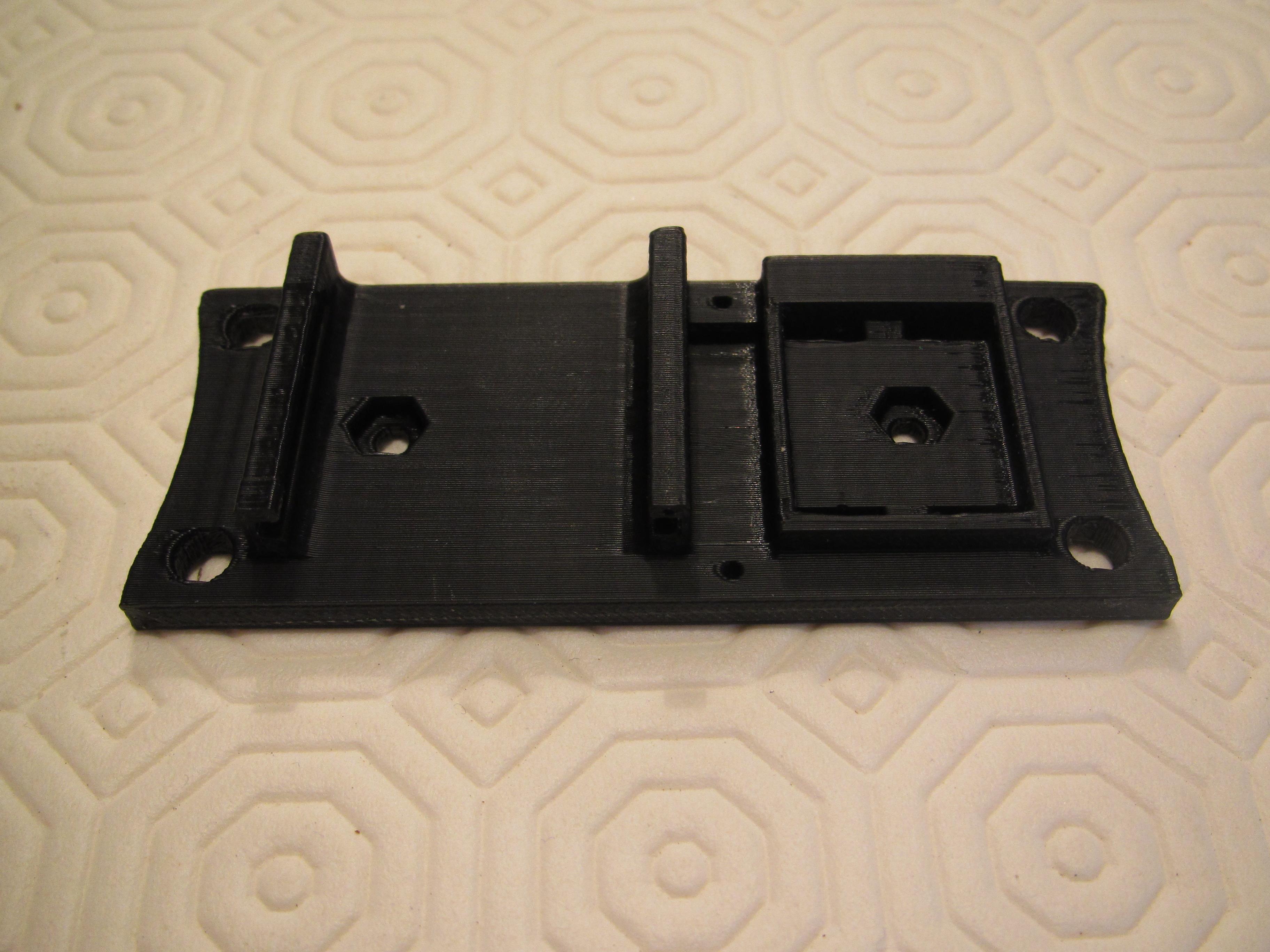
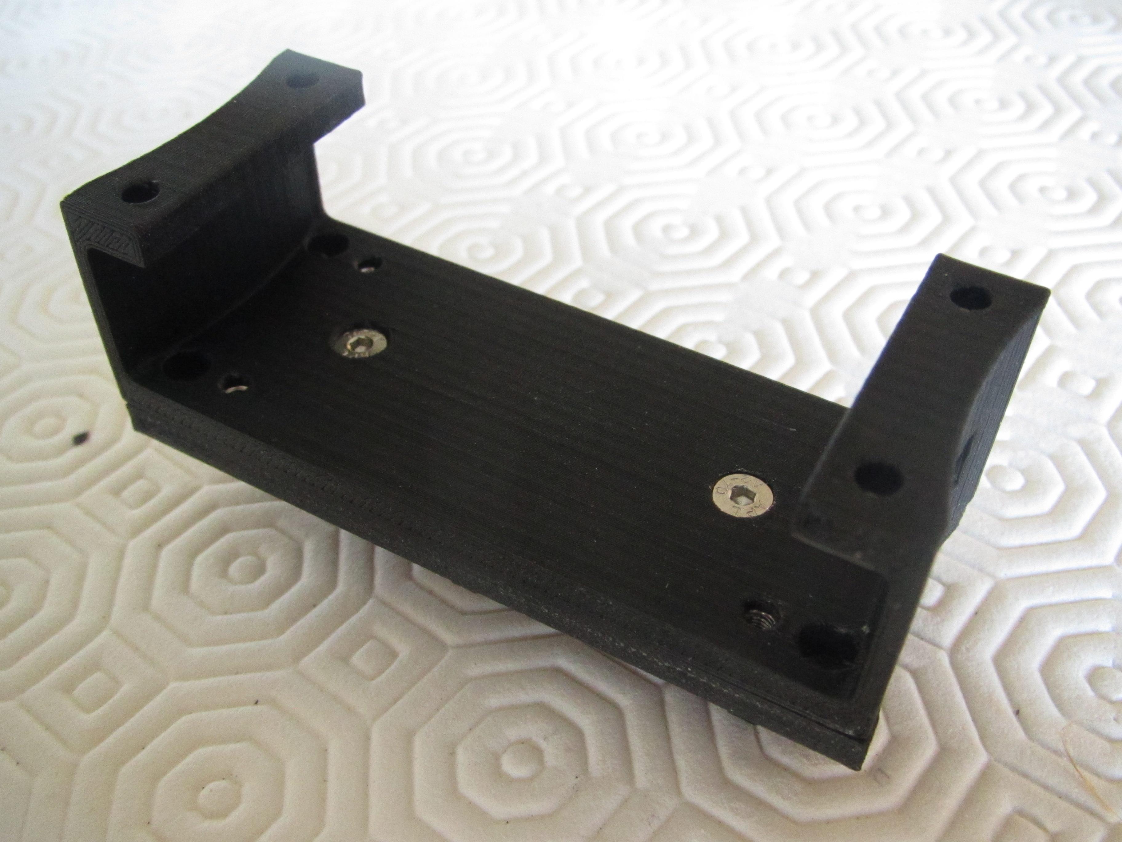
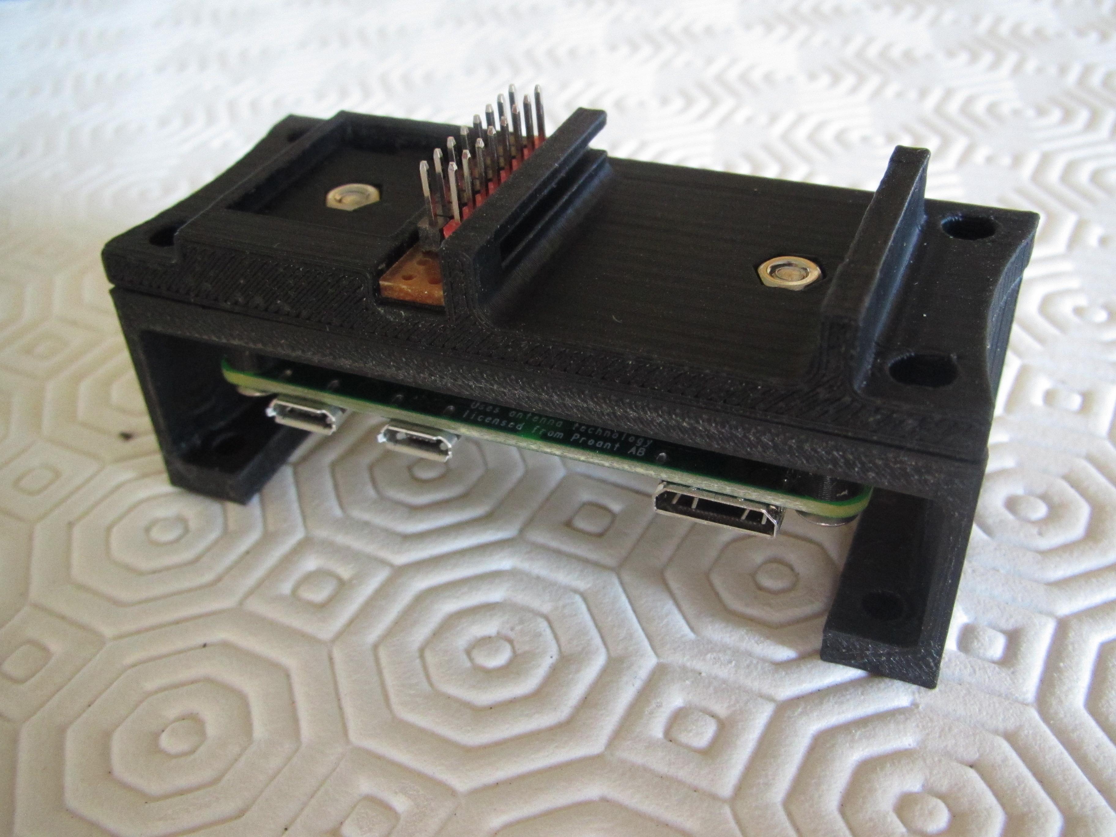
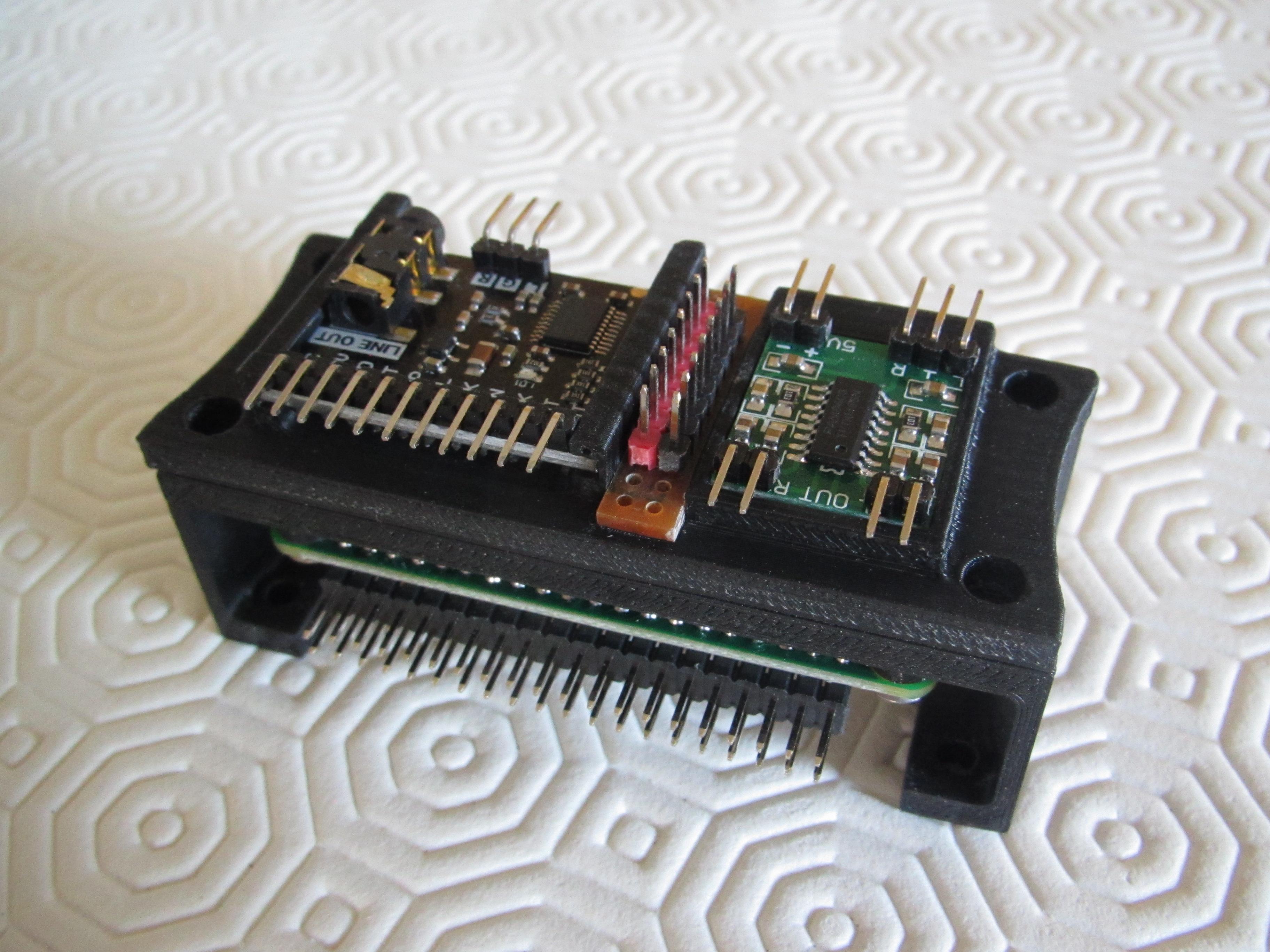
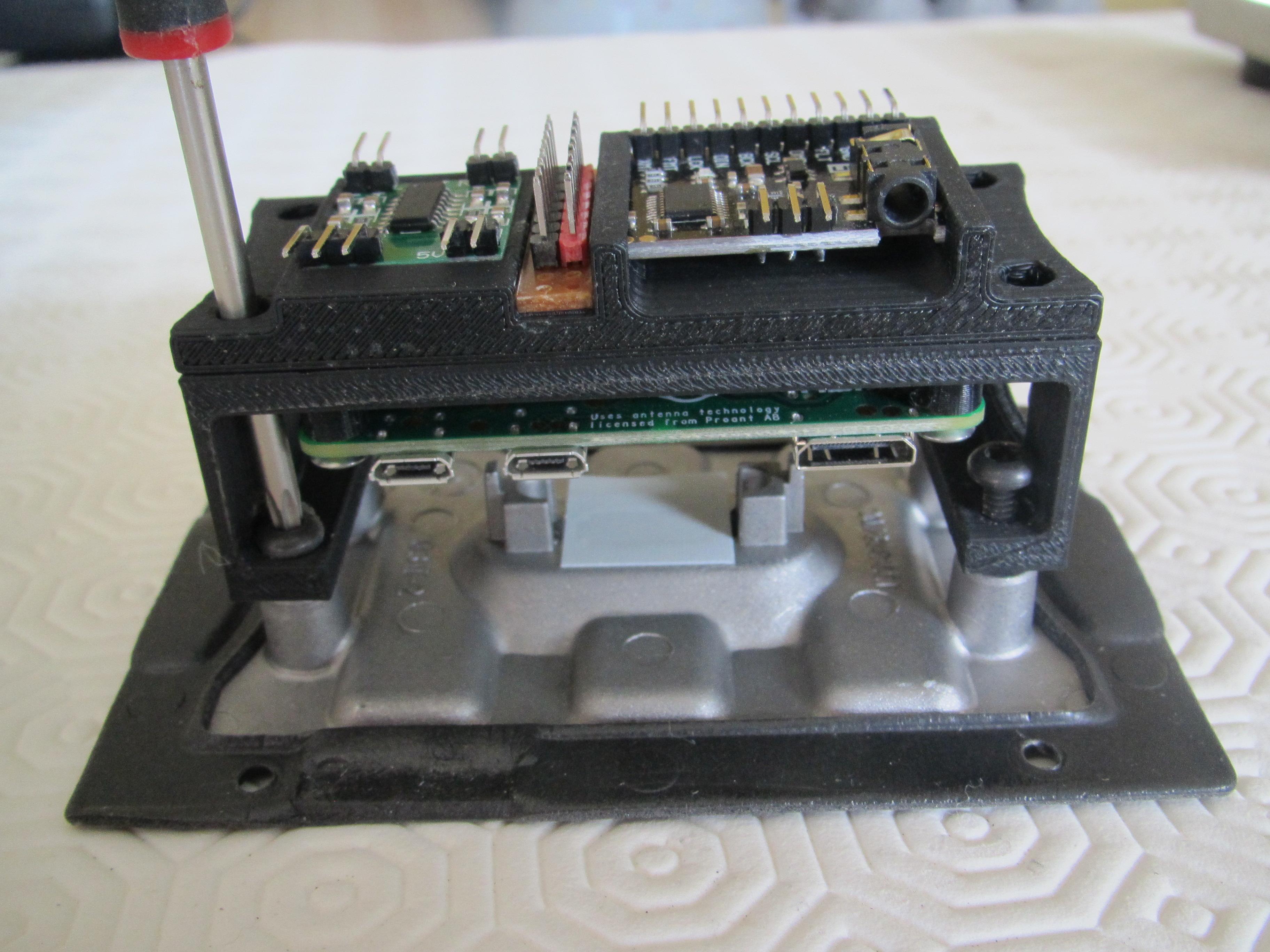
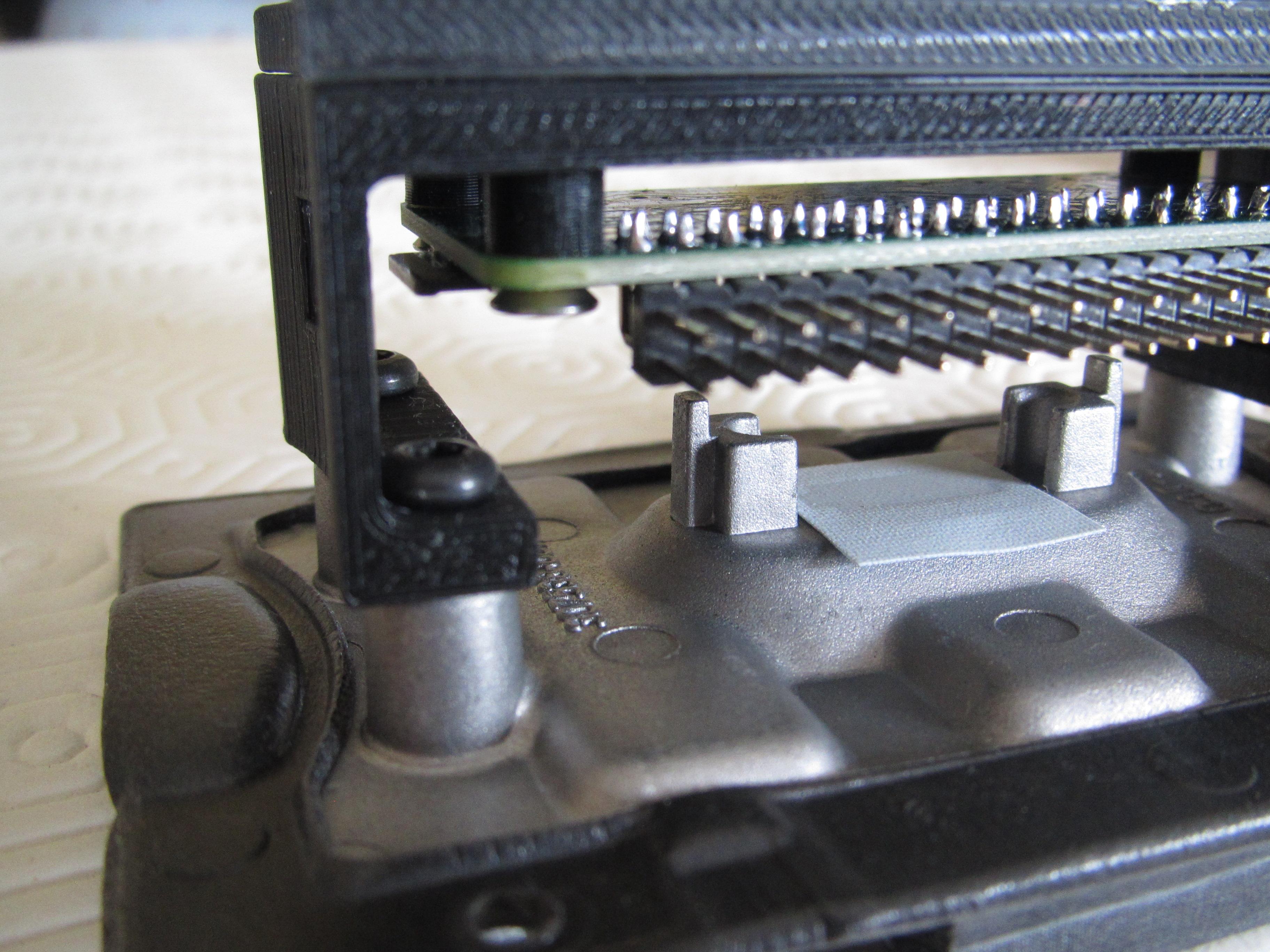
I designed a cradle that would mount to the inside of the alloy heatsink so that I could attach the Raspberry Pi, DAC decoder and amplifier components in a single compact unit.
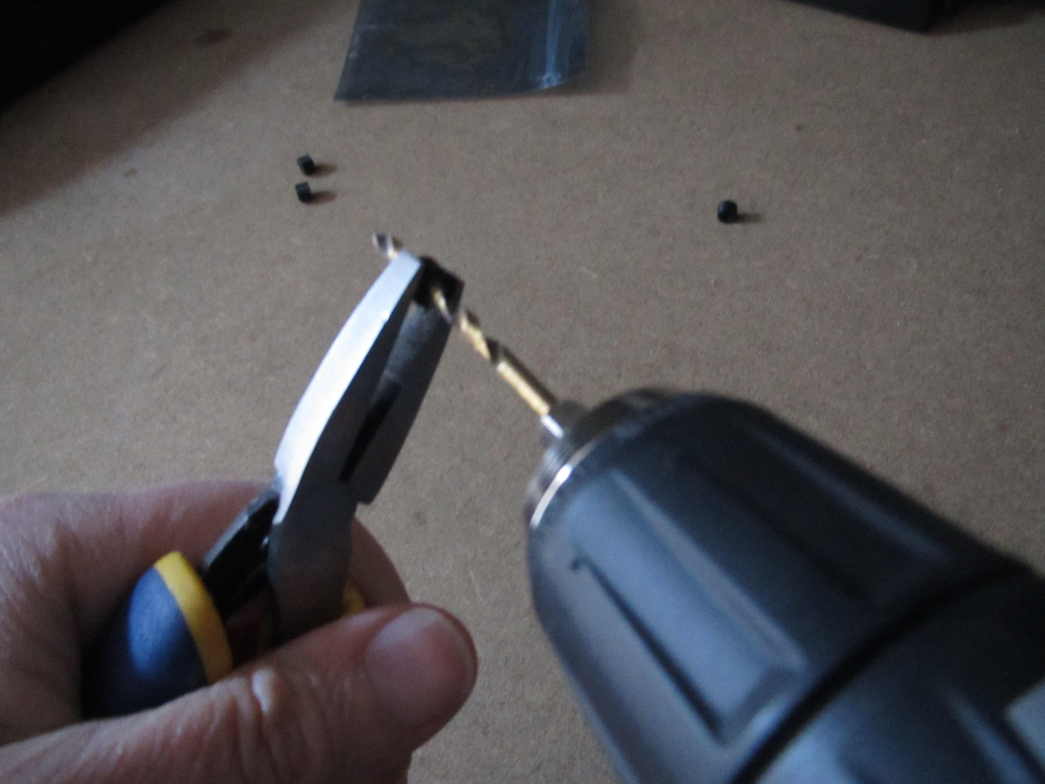
The cradle comes in two parts, the lower part was printed with supports as there is a hole required in the side of the unit, so the micro SD card can be changed without having to disassemble the whole unit. These printed supports can easily be removed using a metal pick and a pair of fine-nosed pliers. The two parts of the cradle can be joined together with M3 machine screws and nuts that are held captive in the design.
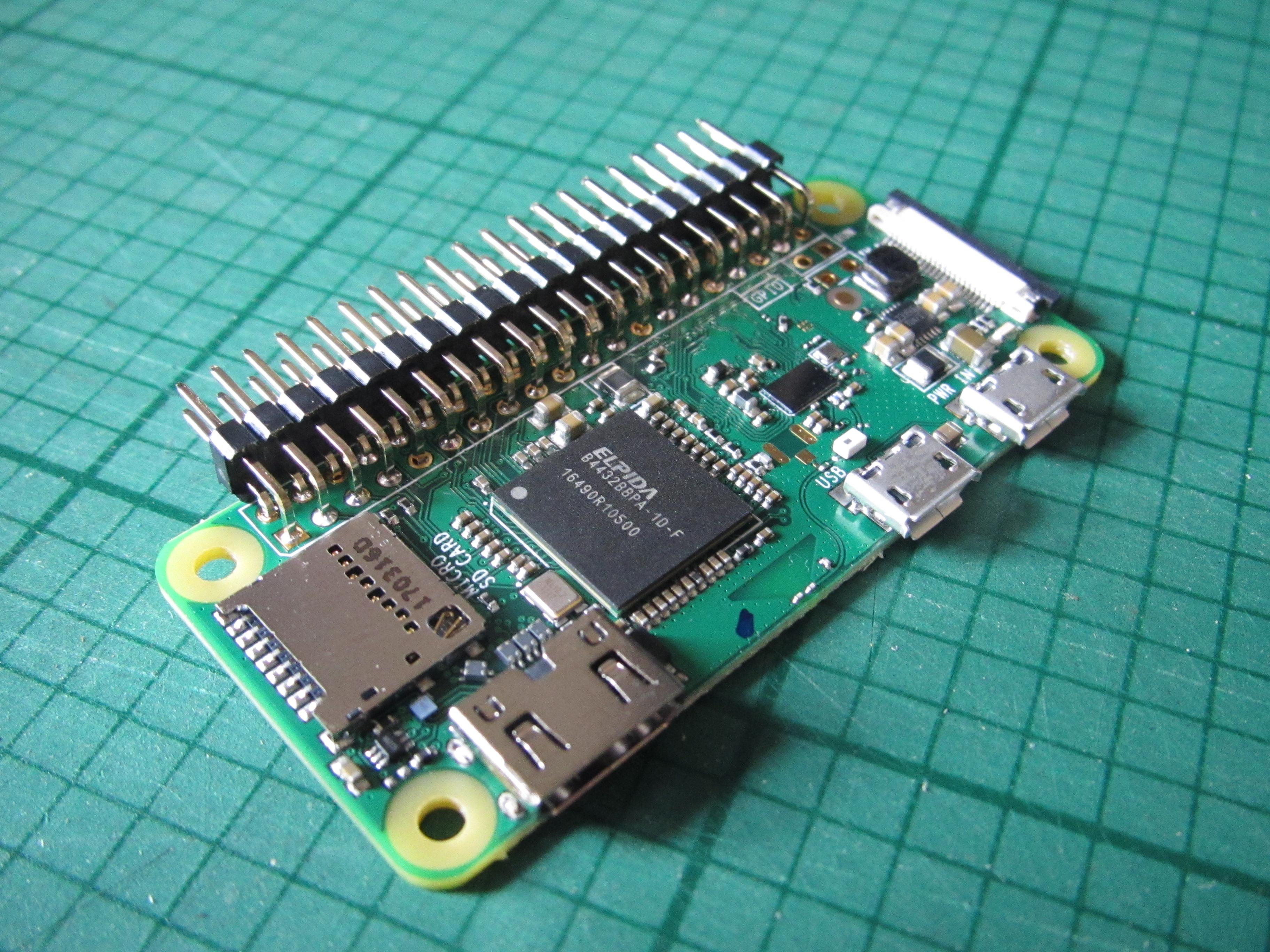
A 40-pin right angle header was soldered onto the Raspberry Pi (RPi).
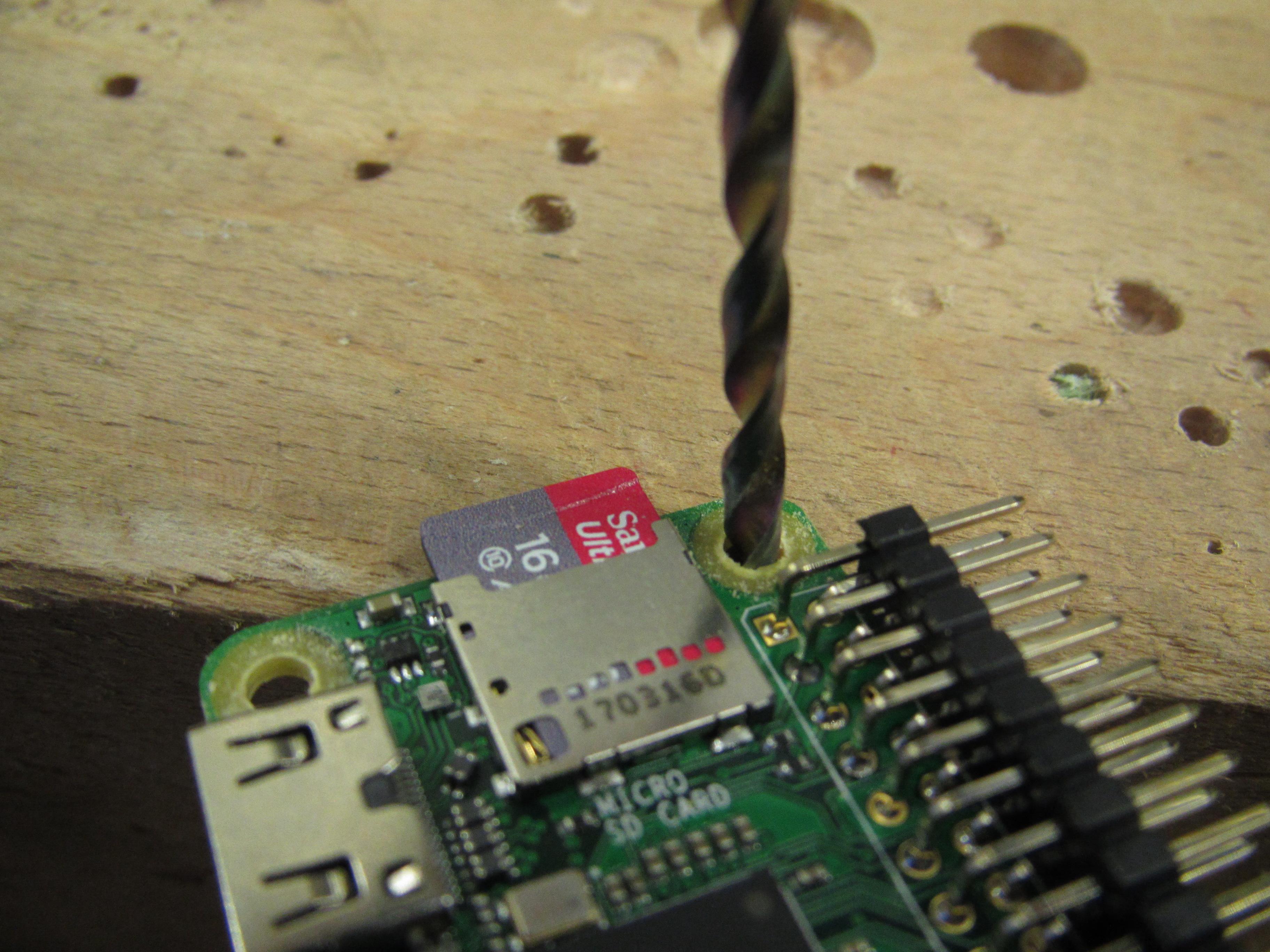
The RPi is mounted on some printed circuit board spacers which are then drilled out so the machine screws pass through easily. This is also done carefully on the Raspberry Pi corner mounting holes.
On the top of the cradle you will see the DAC PCM5102A with soldered right angle headers, a PAM amplifier and a double row of headers mounted on some veroboard to act as a power supply bus bar. The whole of this assembly can be attached to the alloy heat sink panel that attaches to the front of the SoundDock using the original screws.
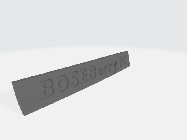
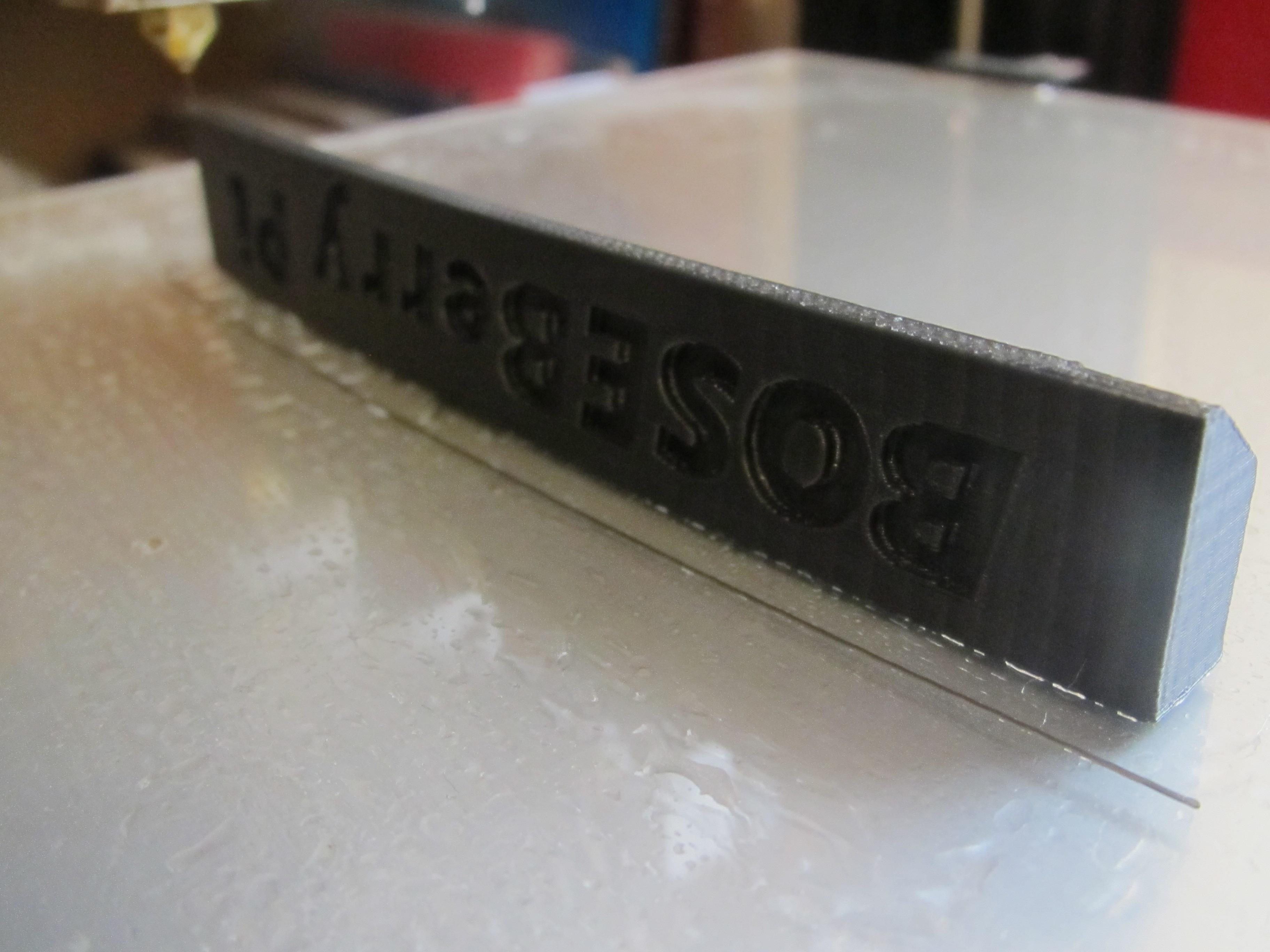
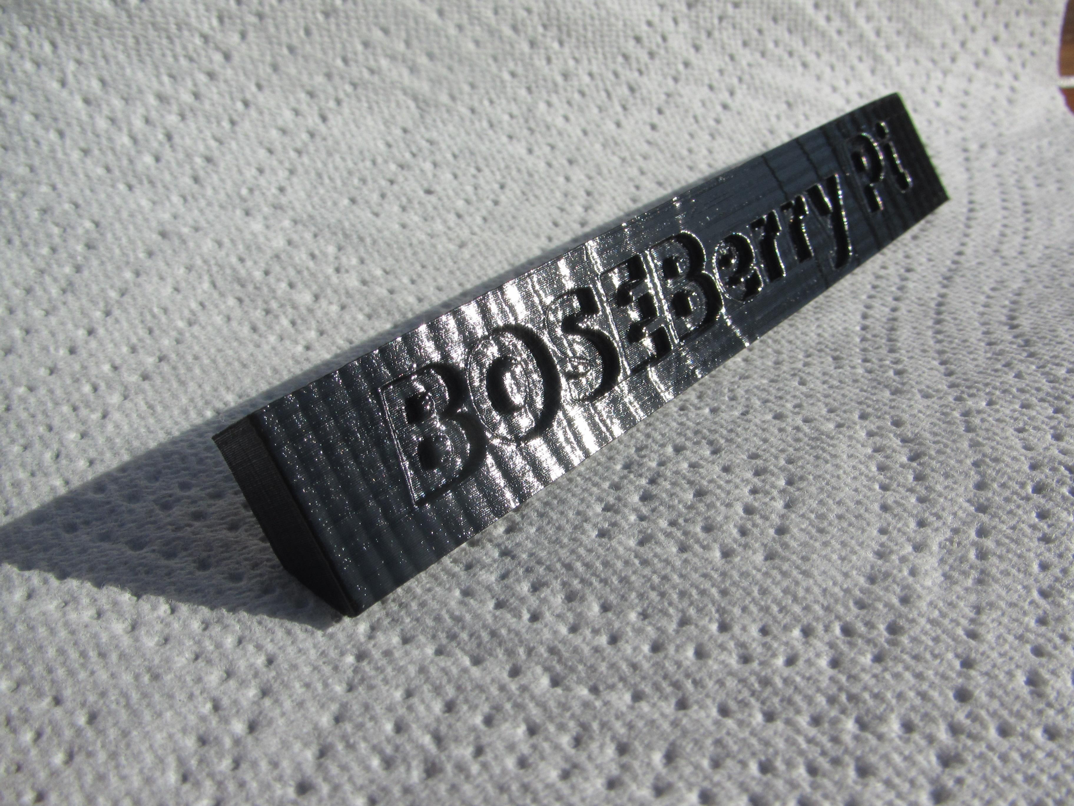
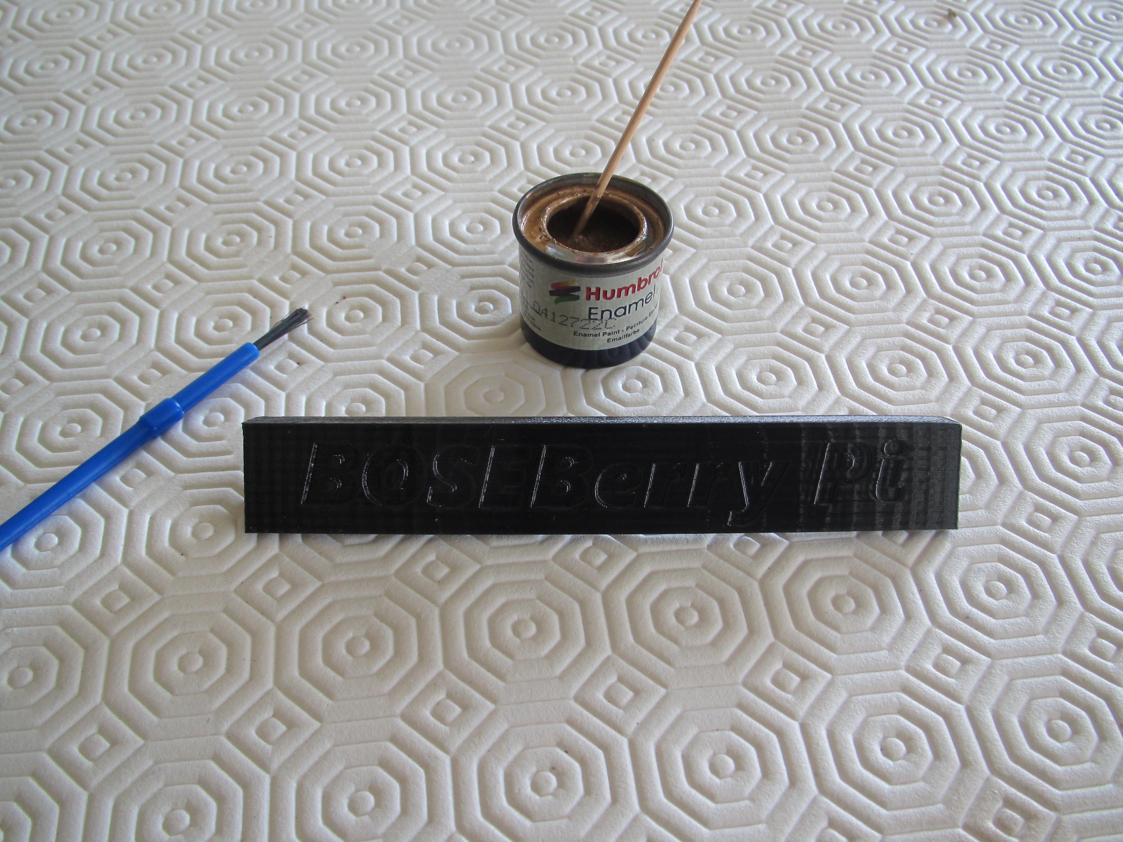
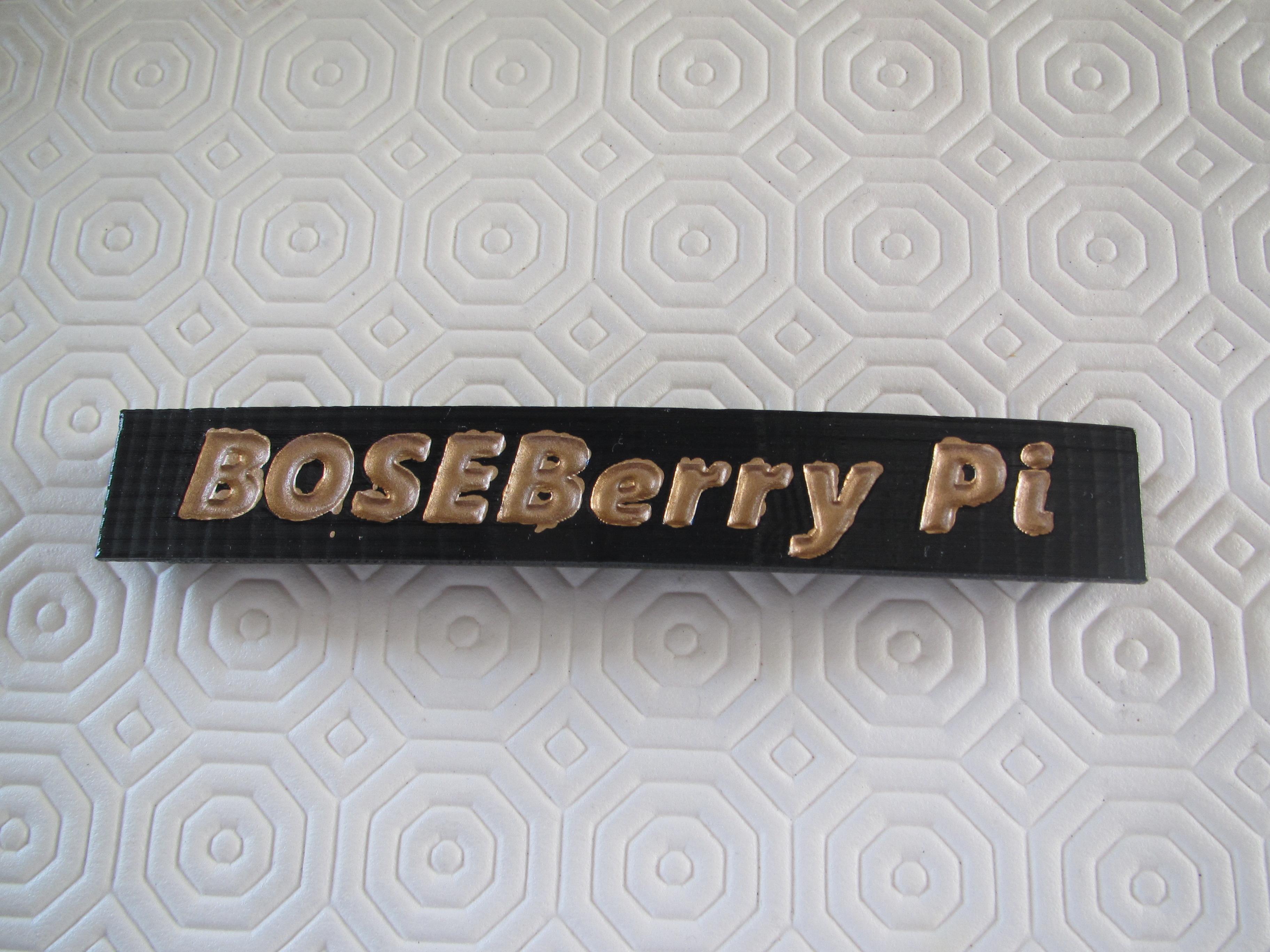
The front name plate was designed to follow the radius of curvature of the case. I used embossed letters and it was printed out accurately, but I didn't think the BOSEBerry Pi name was particularly visible unless it caught the light in the correct way. I decided to paint the embossed letters to make them more visible. I sealed the print with a clear acrylic lacquer spray to fill any voids in the print surface. This should ensure that the next layer of coloured enamel paint didn't bleed through the printed layers of the piece. The enamel paint was built up in several coats. Whilst painting, some capilliary action did draw the paint up to the surface resulting in some smudges, but once it was dry, I was able to clean it up with some wet and dry paper and then add a final coat of clear lacquer to match the glossy finish of the unit.
Configure the Pi
The following instructions are the steps you need to go through in order to configure the radio software.
- Download Buster Lite from https://www.raspberrypi.org/downloads/raspbian/Extract the zipped file – you will have a .img file.
- Format the micro SD card using SD card formatter https://www.sdcard.org/downloads/formatter/
- Use Win32 Disk Imager https://sourceforge.net/projects/win32diskimager/ to write Raspbian Buster onto the SD card (which takes about 10 minutes)
- Attach the Pi to a monitor and keyboard and login with username = pi, password = raspberry
- Type Sudo raspi-config into a console window.
- Menu option 8 – update this tool to latest version.
- Menu option 1 – change the user password and make a note of it.
- Menu option 2 – network options
- (N2) Enter WiFi details for your home network
- (N1) Change hostname to radiopi
- Menu option 3 – Enable Boot options (B1) and (B2) Console auto login
- Menu option 5 – Interfacing options (P2) enable SSH
- Menu option 7 – Advanced (A1) Expand filesystem
- Sudo apt-get update
- Sudo apt-get upgrade (15 minutes)
- Sudo rpi-update (to update firmware)
- RPiZ can now be used ‘headless’ so you can SSH into it to configure the rest of the settings. Log on to your router through a browser (something like 192.168.1.254) and find the ip address of your radiopi. Download Putty and use it to log in to the Pi using the ip address you have just found. The username=pi and use your new password.
- sudo apt-get install lirc # install LIRC (enter y to continue)
- sudo nano /boot/config.txt
- uncomment and change pin number --> dtoverlay=gpio-ir,gpio_pin=23 #pin 16 on the board
- comment out #dtparam=audio=on
- dtoverlay=hifiberry-dac
- comment out RPi4 options dtoverlay=vc4-fkms-v3d and max_framebuffers=2
- ctrl X then Enter then ‘Y’ to save
- cd /etc/lirc
- ls to list the files in the directory
- sudo cp lirc_options.conf.dist lirc_options.conf
- sudo cp lircd.conf.dist lircd.conf
- sudo nano lirc_options.conf
- driver = default
- device = /dev/lirc0
- ctrl X then Enter then ‘Y’ to save
- sudo nano /etc/lirc/lircd.conf.d/HX1838.conf
- Copy in the definitions for HX1838.conf from text file (ctrl-insert to paste into the console)
- ctrl X then Enter then ‘Y’ to save
- cd /etc/lirc/lircd.conf.d
- ls to see files
- sudo mv devinput.lircd.conf devinput.lircd.conf.dist (to disable it)
- sudo nano /etc/lirc/lircrc
- paste in the configuration code for lircrc
- ctrl X then Enter then ‘Y’ to save
- sudo apt-get install mpd – enter ‘Y’ to continue (takes some time)
- sudo apt-get install mpc
- sudo nano /etc/rc.local
- comment out all the code except exit 0 at the end
- #add these next comments before exit 0
- add irexec -d
- add mpc stop
- add mpc volume 30
- #reduce the power requirements
- # switch off hdmi as this unit is headless
- /usr/bin/tvservice -o
- ctrl X then Enter then ‘Y’ to save
- Finally, create a new asound.conf by typing sudo nano /etc/asound.conf and entering the following:
- pcm.!default {
- type hw card 0
- }
- ctl.!default {
- type hw card 0
- }
- ctrl X then Enter then ‘Y’ to save
- sudo nano /etc/mpd.conf
- scroll down to amend these settings
- audio-output{
- Type “alsa”
- Name“My ALSA Device”
- Device “hw:0,0”
- Mixer_type “software”
- Mixer_device “default”
- Mixer_control “PCM”
- Mixer_index “0”
- }
- ctrl X then Enter then ‘Y’ to save
- sudo reboot
- You are now ready to connect the wires.
I configured the radio stations to the following, but you can change the url streams and use any radio stations you want. See the attached lircrc configuration file.
Key 0 = Jazz FM http://edge-ads-02-gos1.sharp-stream.com/jazzfmmobile.mp3
Key 1 = Absolute Classic Rock http://ais.absoluteradio.co.uk/absoluteclassicrock.mp3
Key 2 = BBC Radio 2 http://a.files.bbci.co.uk/media/live/manifesto/audio/simulcast/hls/uk/sbr_high/ak/bbc_radio_two.m3u8
Key 3 = Classic FM http://vis.media-ice.musicradio.com/ClassicFMMP3
Key 4 = BBC Radio 4 http://a.files.bbci.co.uk/media/live/manifesto/audio/simulcast/hls/uk/sbr_high/ak/bbc_radio_fourfm.m3u8
Key 5 = BBC Radio 5 http://a.files.bbci.co.uk/media/live/manifesto/audio/simulcast/hls/uk/sbr_high/ak/bbc_radio_five_live.m3u8
Key 6 = BBC Radio 6 Music http://a.files.bbci.co.uk/media/live/manifesto/audio/simulcast/hls/uk/sbr_high/ak/bbc_6music.m3u8
Key 7 = BBC Hereford and Worcester http://bbcmedia.ic.llnwd.net/stream/bbcmedia_lrhandw_mf_p
Key 8 = Absolute 80s Music http://ais.absoluteradio.co.uk/absolute80s.mp3
Key 9 = Absolute 90s Music http://ais.absoluteradio.co.uk/absolute90s.mp3
Up Arrow = volume up
Down Arrow = volume down
Key Left = Clear playlist
Key Right = Clear playlist
Key OK = Play
Key Back = Toggle (which pauses live play)
Key Exit = Stop
Wire Up the Project
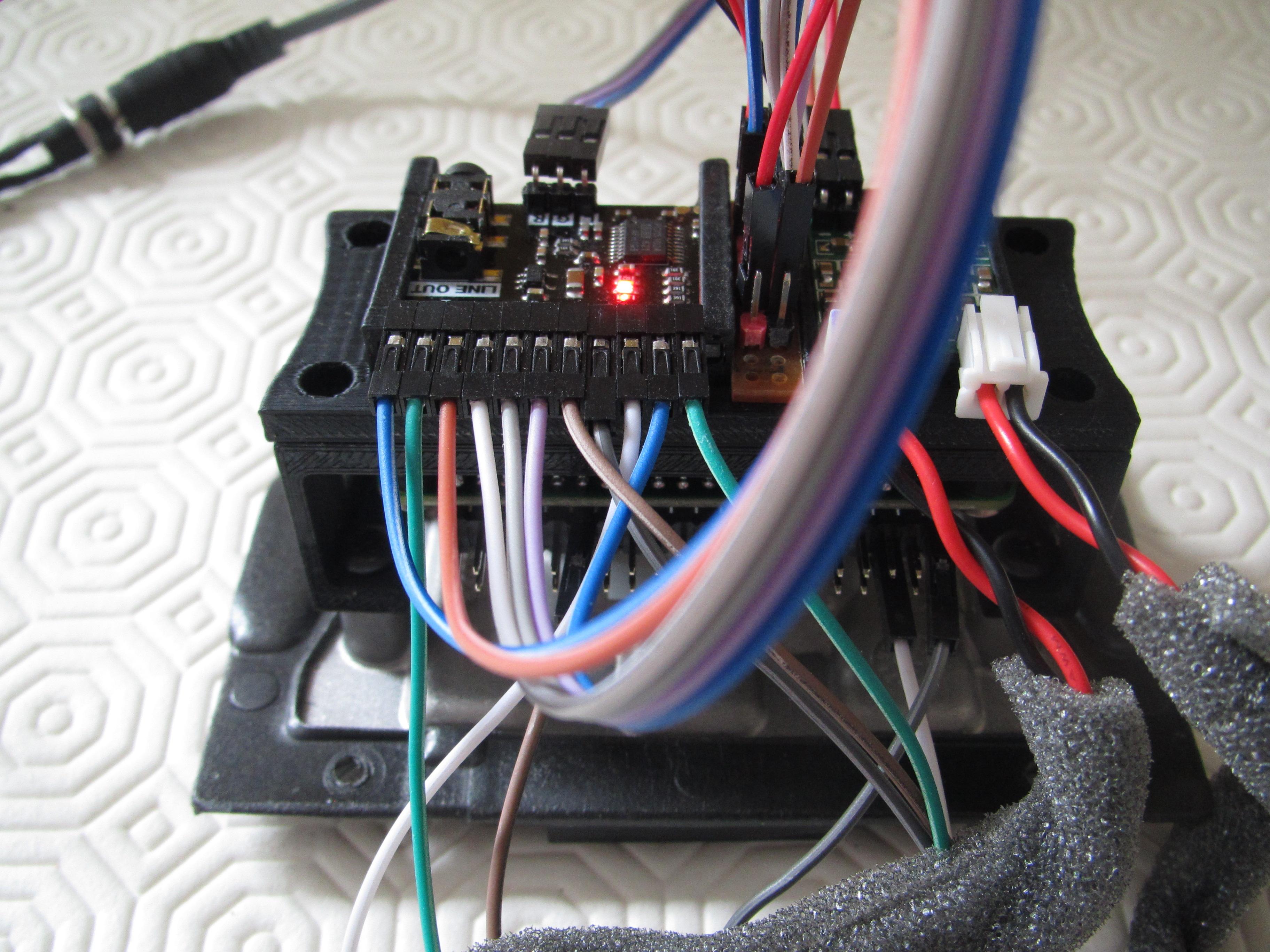
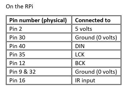
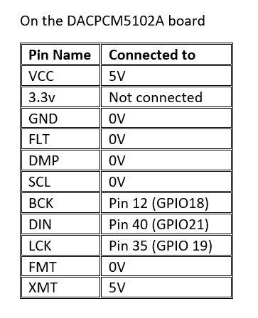
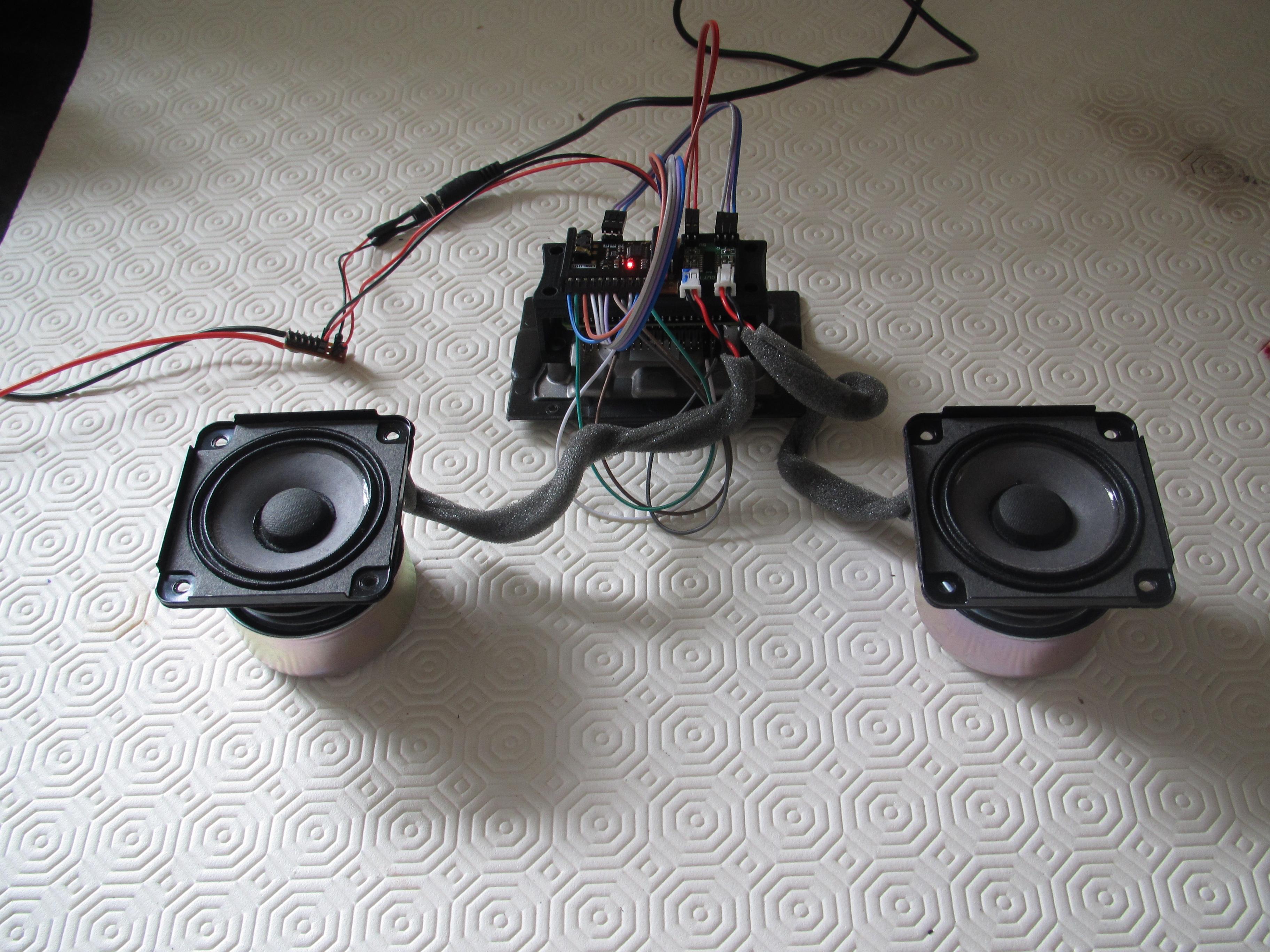
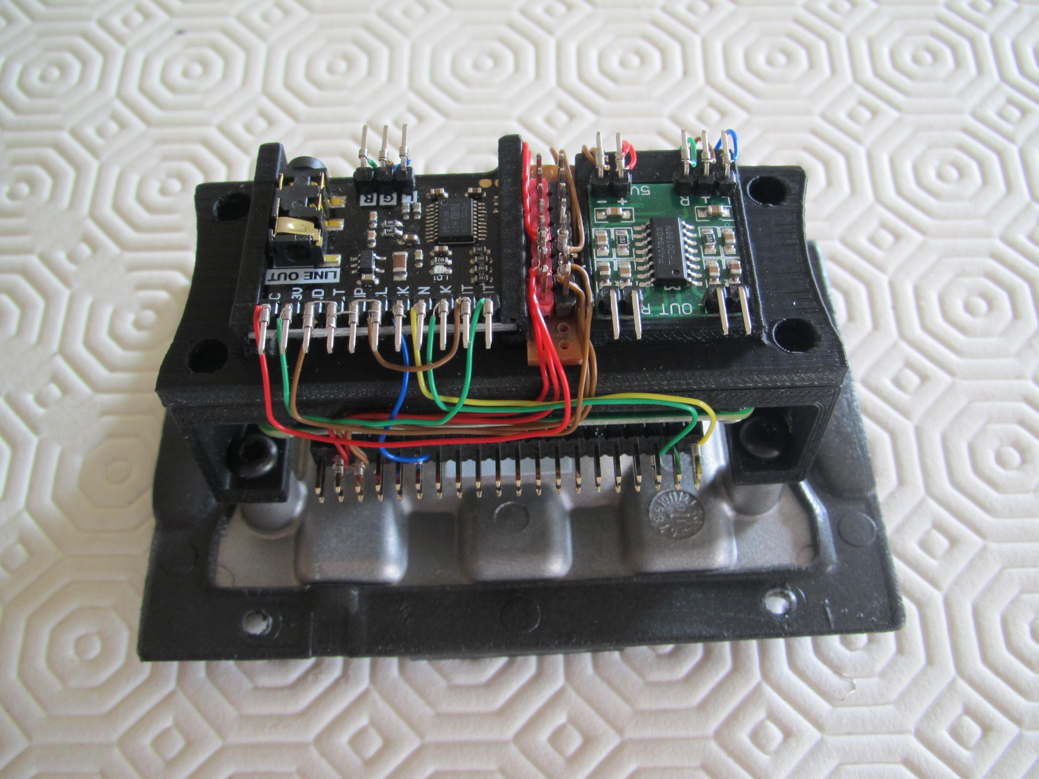
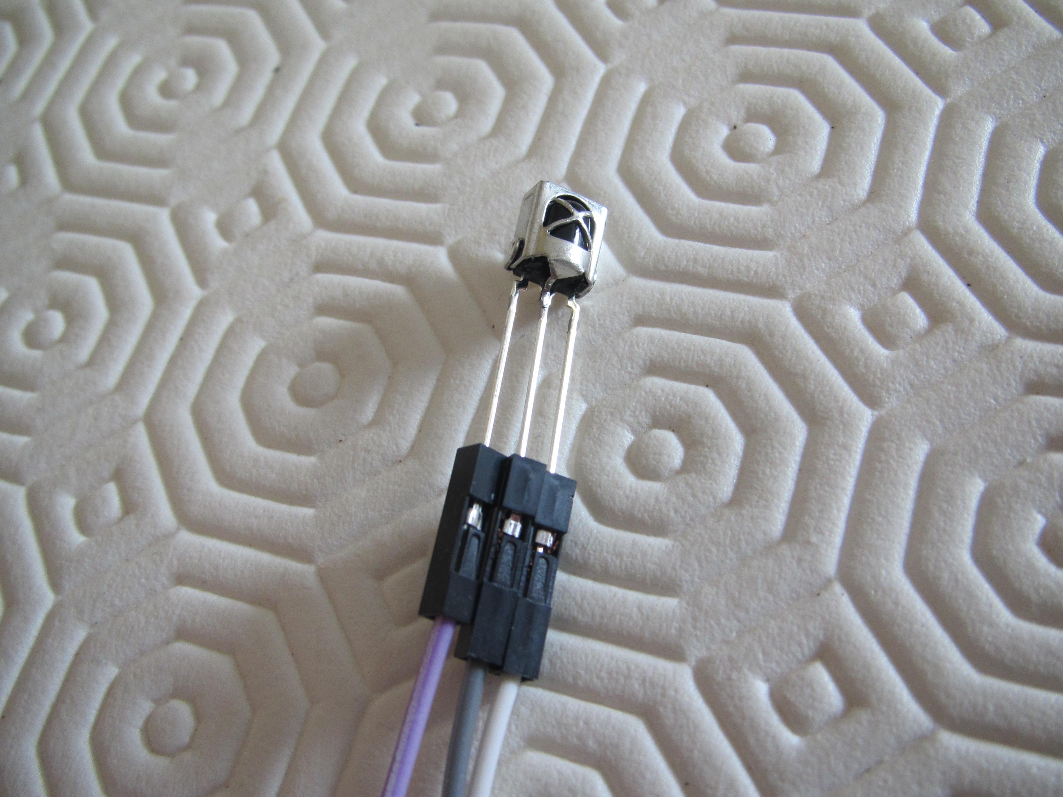
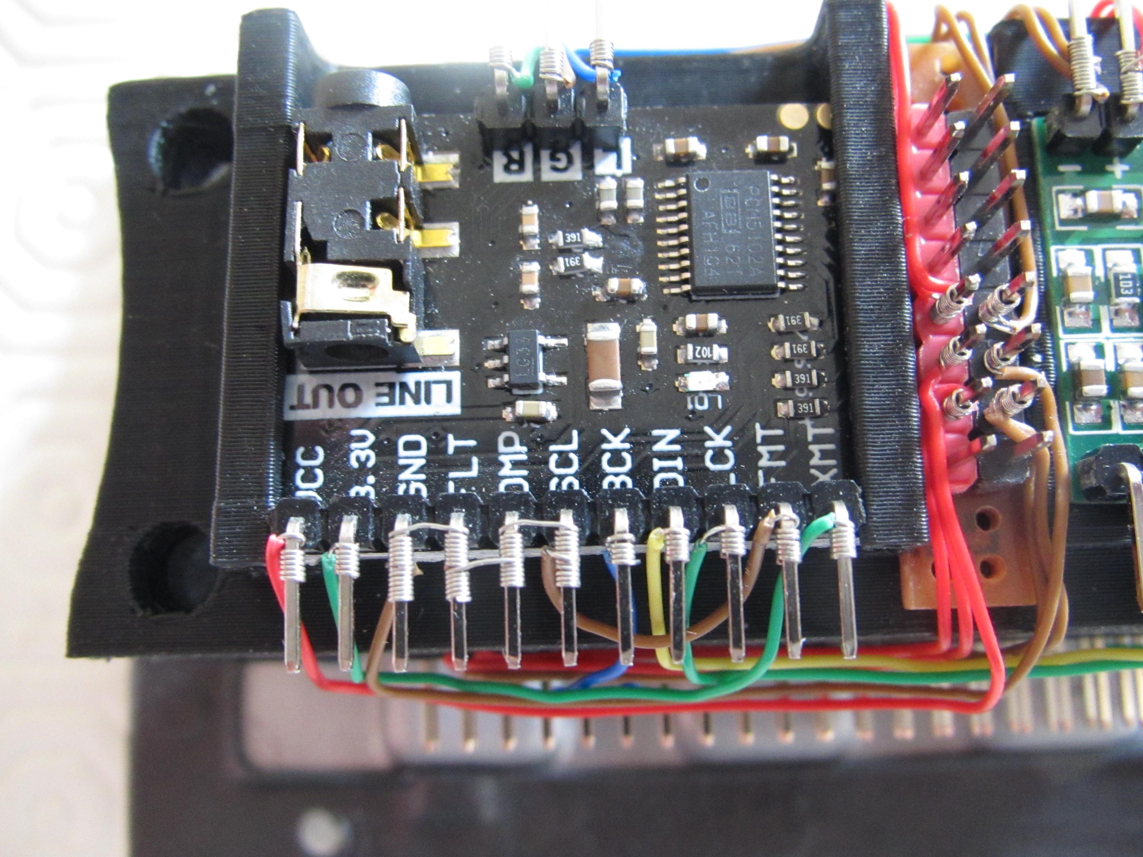
Connect the circuits up using the wiring tables above.
I originally built the prototype on a breadboard to check that it worked. I was then able to transfer the wire connections to the components I had installed, using dupont connectors on the headers. Again, I was able to test to check that the unit was still working. Finally, I decided to make the final connections using a wirewrap tool. This provides a very neat way to connect the components and has the added bonus that connections can easily be 'undone' if necessary. The electrical connections made using this method are so good, they don't actually need soldering.
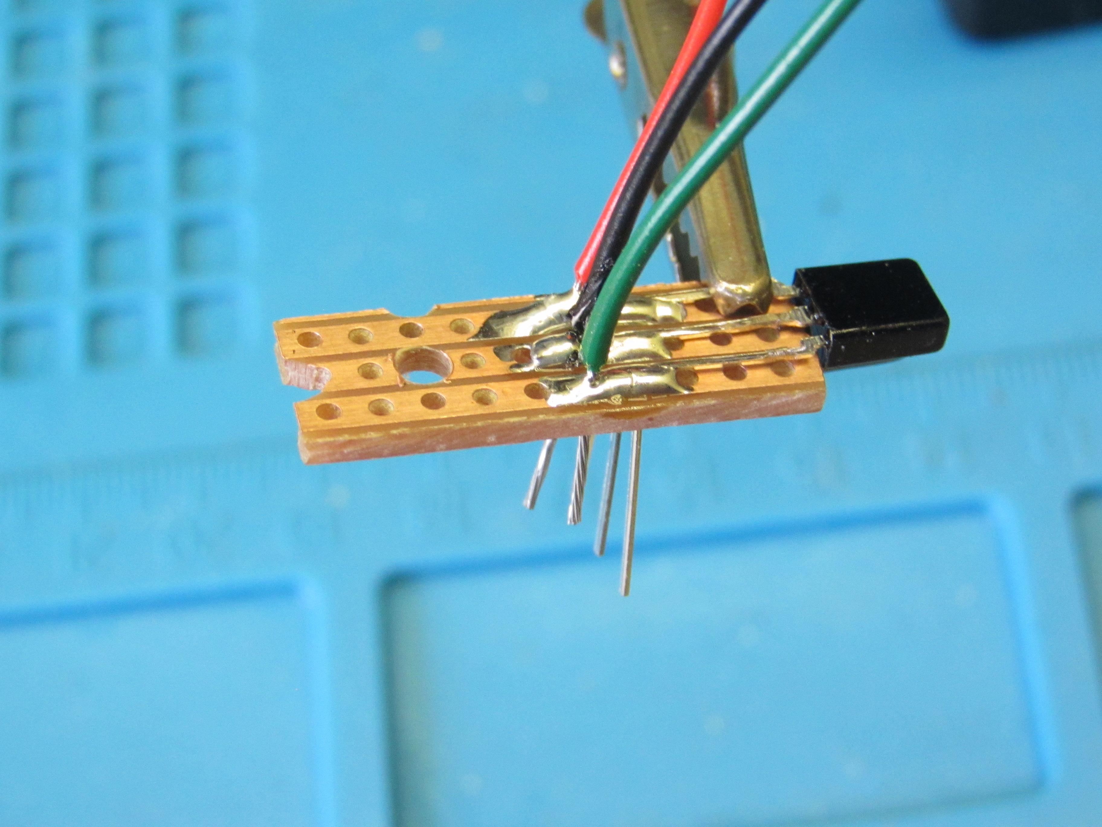
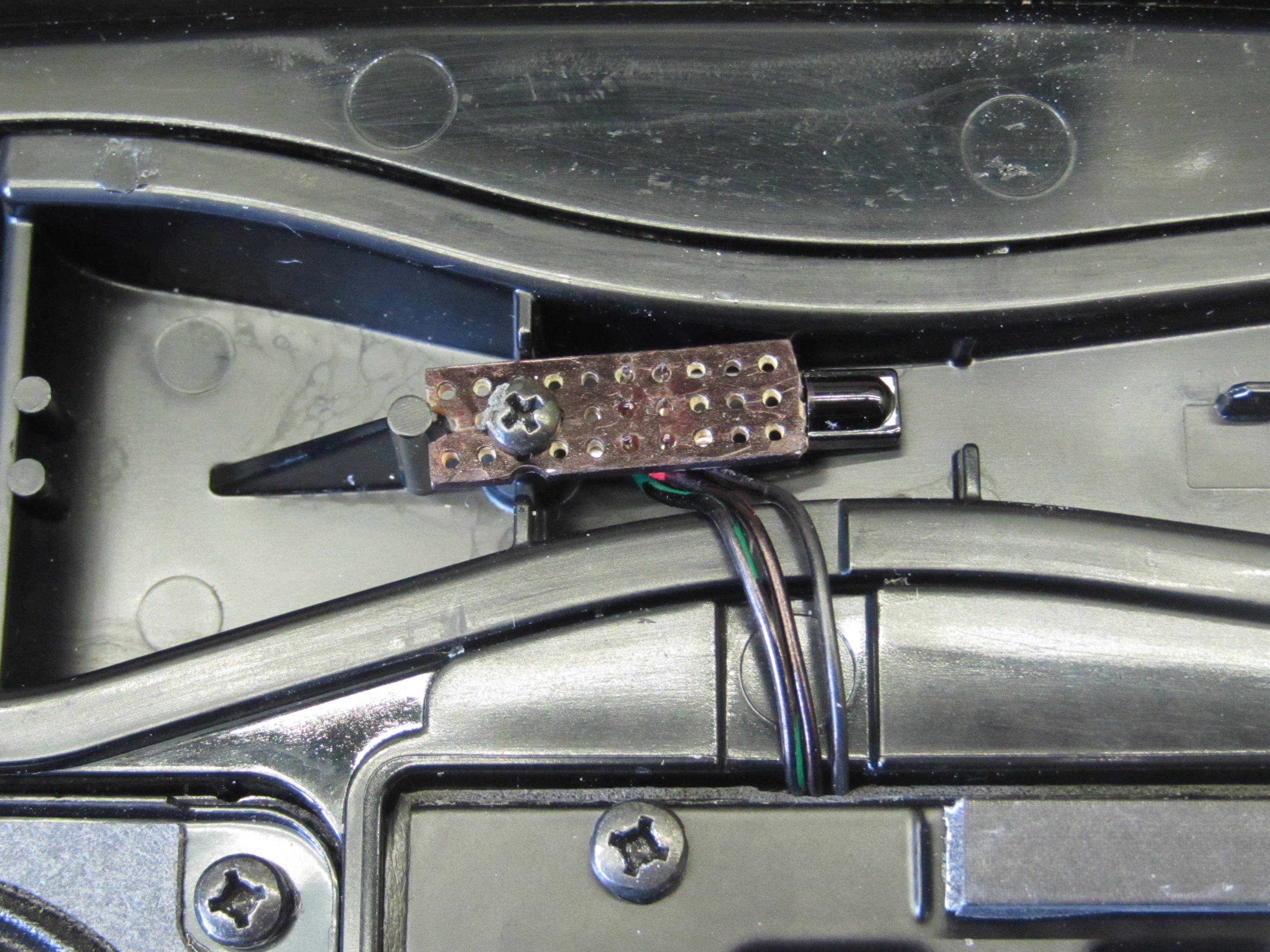
The IR led receiver was added into the project by soldering it onto a small piece of veroboard which was then mounted in the place of the original LED at the front of the case. The wires were kept short and fed through the built in channel to connect to the RPi. This receiver will sit behind the fine wire mesh grill so that it is able to 'see' the IR signal from the remote control unit.
Once the speakers have been secured in the cabinet, they can be attached to the stereo channels of the amplifier output. The female power supply jack socket can be threaded through the 3D printed support plate and wired into the bus bar of the circuit. The whole unit is powered by a 5v 3A plug in transformer.