BB8 - Mobile Controlled and 3D Printed StarWars Robot
by yolabs007 in Workshop > 3D Printing
726 Views, 1 Favorites, 0 Comments
BB8 - Mobile Controlled and 3D Printed StarWars Robot
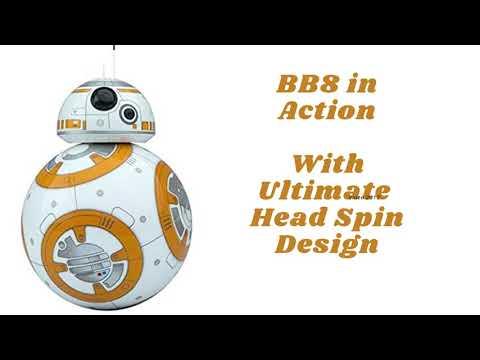
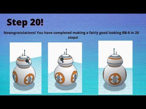
Like Most I am also a Big Fan of StarWars and always wanted to create one cool robo for me. Thanks to tinkercad, fusion 360, 3D printing and embedded technology - finally we have one while many more are coming soon.
Below video and pictures explains how this has been achieved.
Also you can use the TinkerCAD link to access the model which has been made public.
Supplies
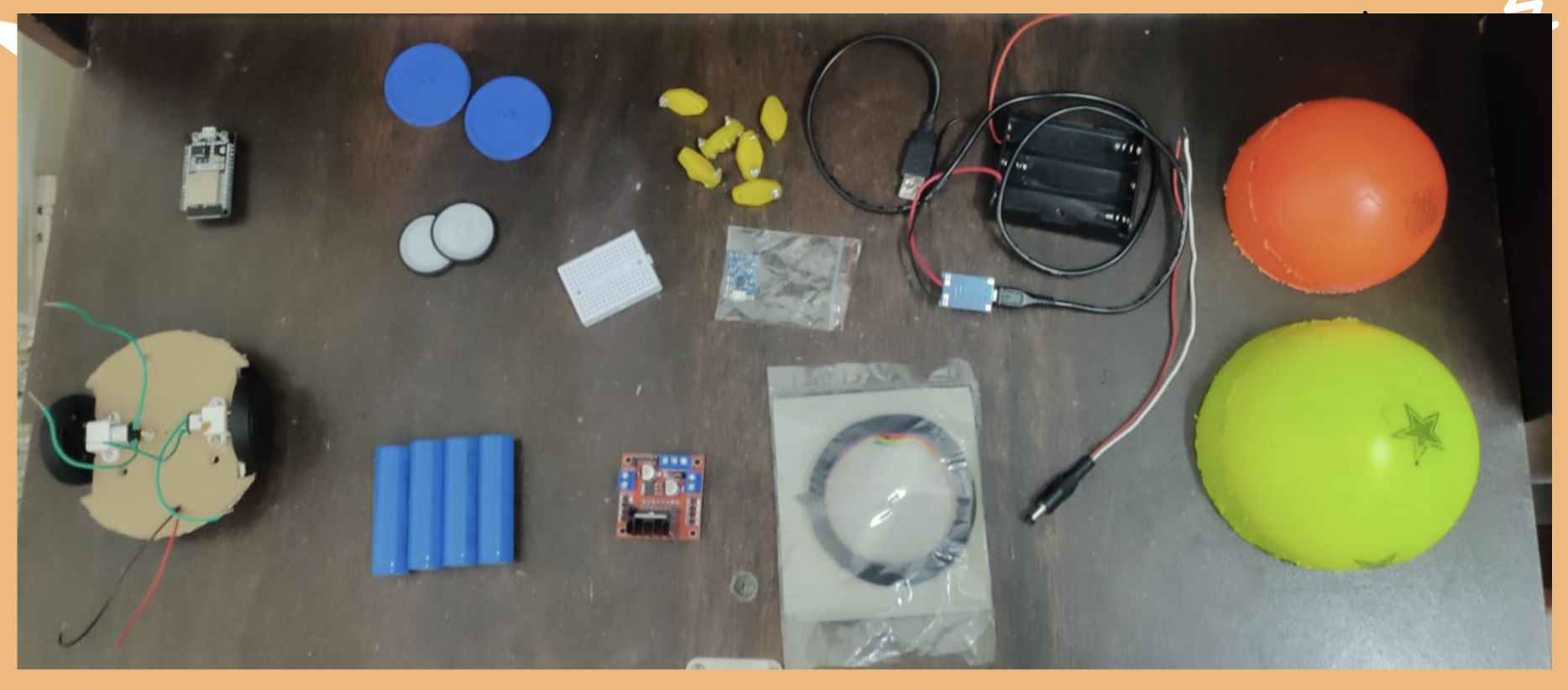
- TinkerCad
- Fusion360
- Access to 3D printer - in this case (Creality ender 3.0) but you can use anyone
- ESP32
- N20 Motor
- 18650 Battery - 3 Nos
- 18650 Battery Holder
- TP4056
- Castor Wheel
- N20 Motor Wheels
- Breadboard
- DC Jack
- Spherical Balls
TinkerCAD -Design the Lower Body
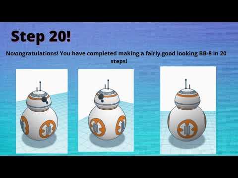
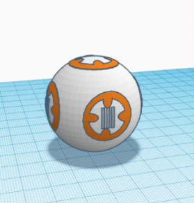
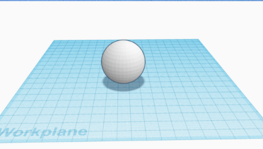
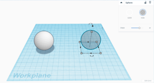
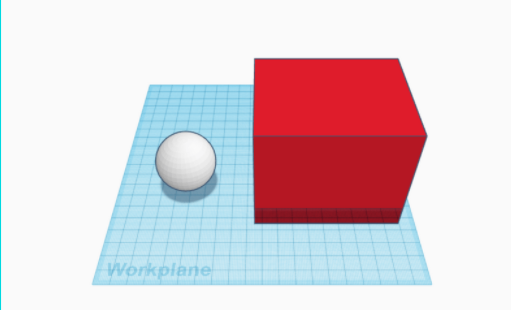
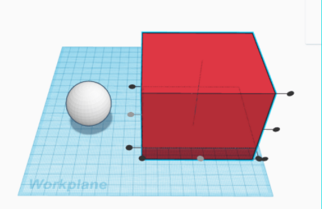
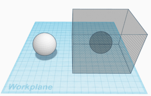

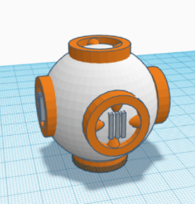
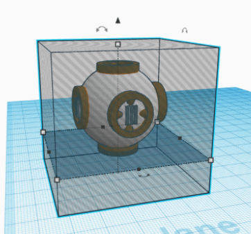
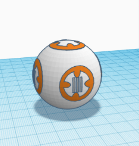
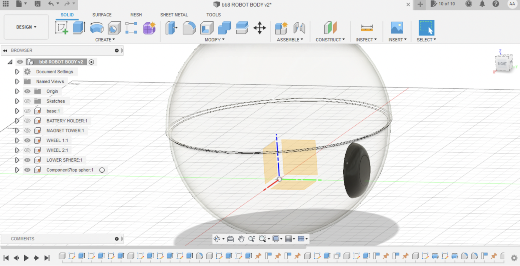
First We used tinkercad to create a 3D model of BB8. Note This model is created mainly to understand the design and aesthetic aspects of BB8.
Design the lower body:
- Get A sphere of dimension of 40x40x40mm
- Duplicate the Sphere and make it a hole
- Bring a Cube 60x60x60 mm. you can vary the dimension as long as it is covering the sphere with a margin.
- Align the Cube and Hole sphere. Make sure you align it in centre by horizontal only.
- Group Both the Objects and then make them as a hole rather solid. Please cross check with the picture i have provided to double ensure.
- Create the BB8 rings(6 numbers) with details as shown in picture
- Attach the 6 rings to the white ball which was created @ point-1. Use workplane (shortkey -W) for ease.
- Now use the cutter (ref picture and video) to trim the excess ring material
- Now align and group the objects
- Refer the last picture if everything is as per instructions you should be having a beautiful lower Body of BB8 with all minute details
Note: As this body rolls on surface it can not have any projection , including sphere joints
TinkerCAD - Design the Head
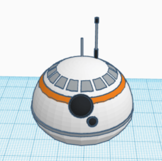
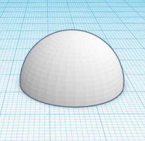
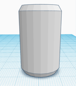
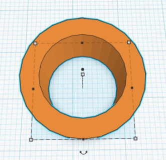
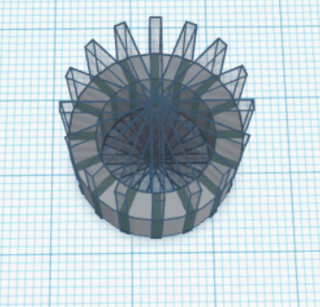
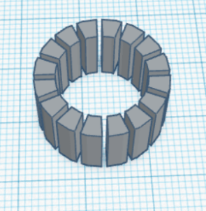
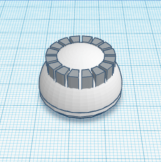
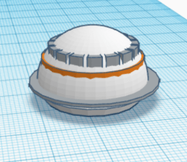
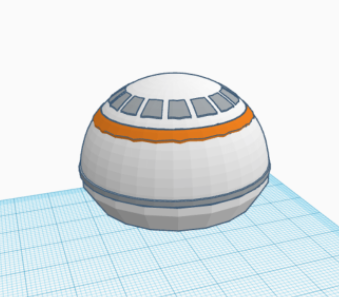
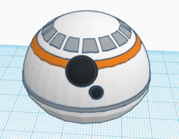
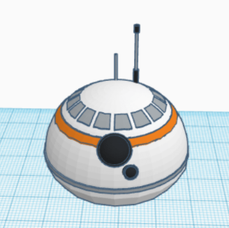
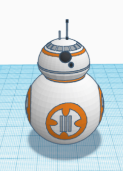
Design the Head:
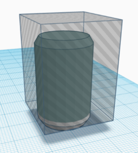
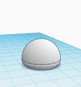
- Bring a Half -Sphere and make the dimesion 25x25x12.5 mm
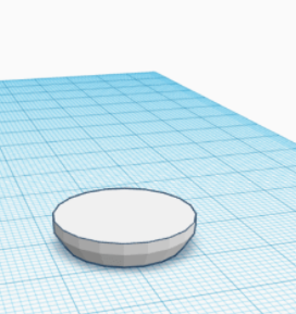
- Take a Cylinder and make the dimension - 25x25x35 with bevel 1.5 (refer-pic)
- Now cut the top 30 mm of cylinder and keep the bottom portion
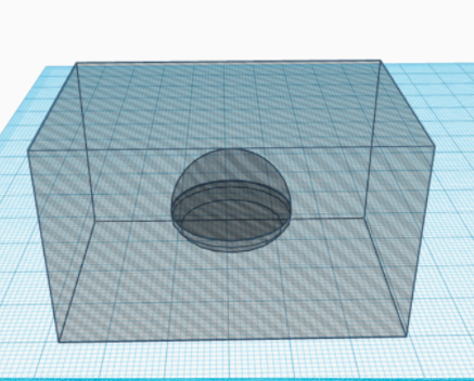
- Create the cutter (same as done in step-1) for half sphere
- BB8 head is having very specific design for that bring a ring
- create 16 equal partition of the ring using duplicate tool. To cut the ring you can use a thin plate made out of the cube
- Place the ring on the head as well as other details
- Use trimmer/cutter (point-4) to get the desired shape of head
- Place the eyes using a sphere (5mm) for big eye and cylinder(3mm) for small eye.
- Place the antenna on the head. Refer any BB8 pic to guess the right location
- Please the head on the body created in Step-1
Main Body Assembly
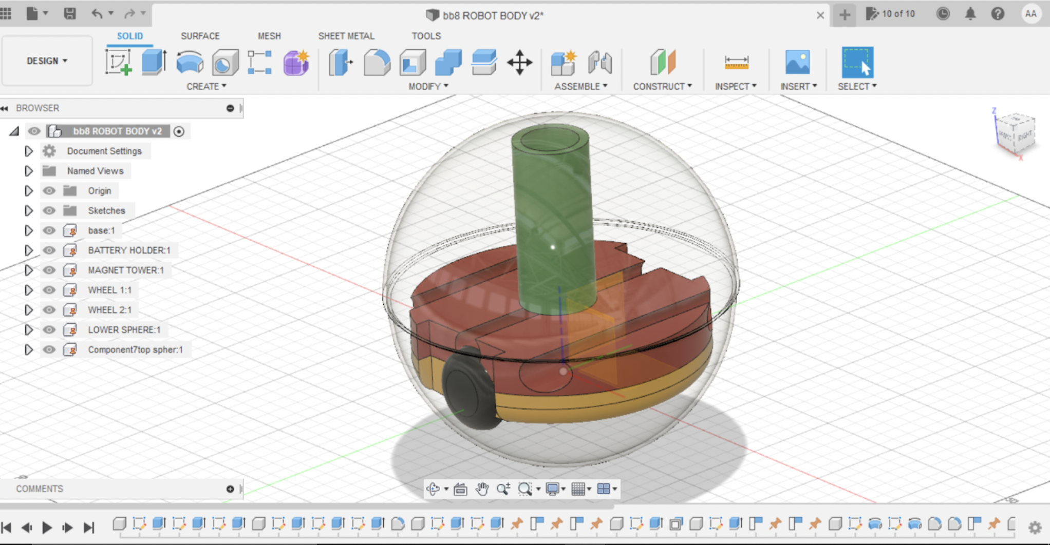
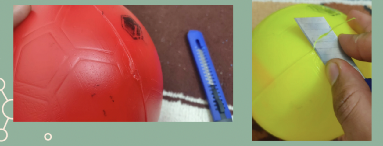
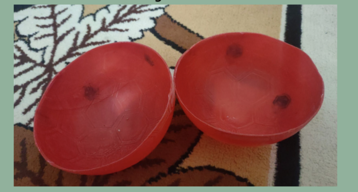
WE have created a quick prototype using most of regular Materials. But all the used items can be 3D printed. But 3D print a half sphere which take 8 hours - its easy to buy a ball in 2 $ and cut it into two half
- Get Plastic balls (hard Surface) from any nearby shop or order through amazon
- Cut the ball in two half - Seam on the ball may be a great help
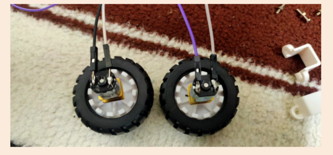
- Prepare the N20 Motors- solder the wires and check the rotating direction
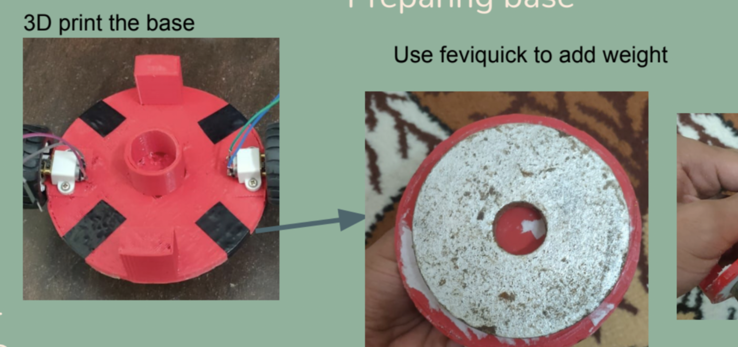
- 3D print the base - use the stl file attached
- Attach any heavy weight to the bottom of the base to avoid topple
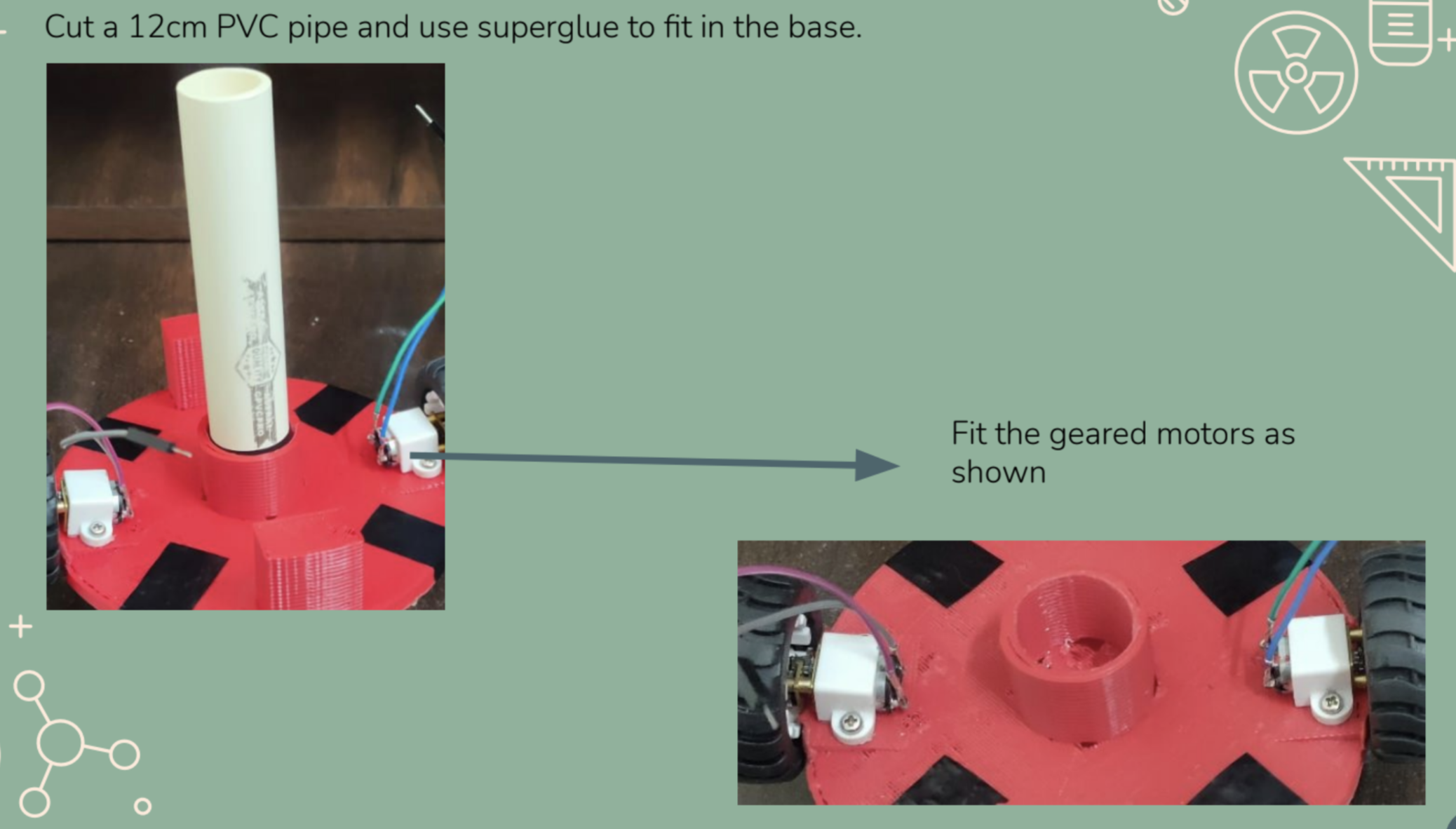
- Cut a 12 mm dia PVC pipe. Keep the length based on your ball dia, ensure the PVC pipe top end is just 1 cm below the sphere surface. A big gap will result in fall of the head due to poor magnetic force
You can use any material and plastic balls to get the outer body or you can 3D print the same
Assemble Motors and Electronics
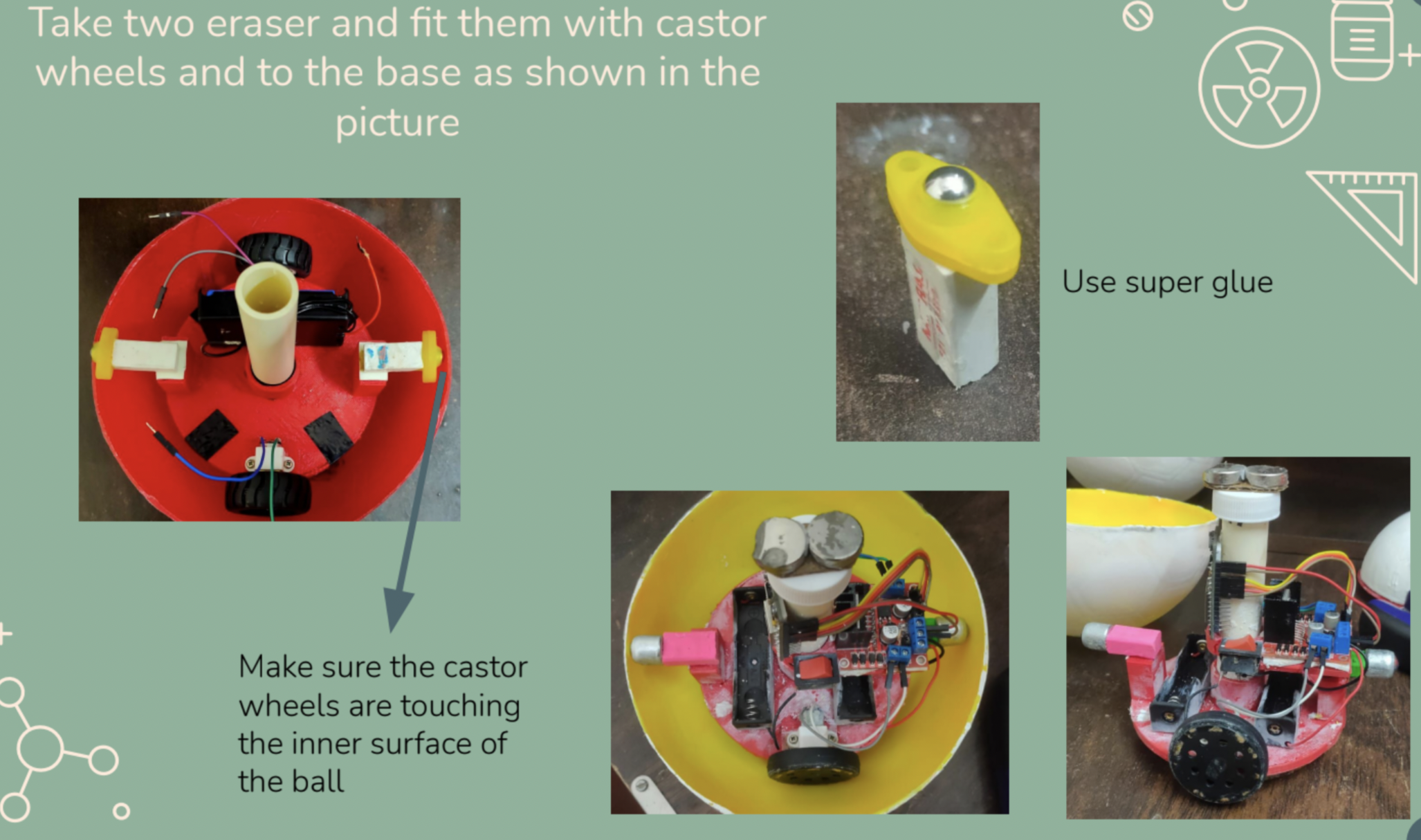
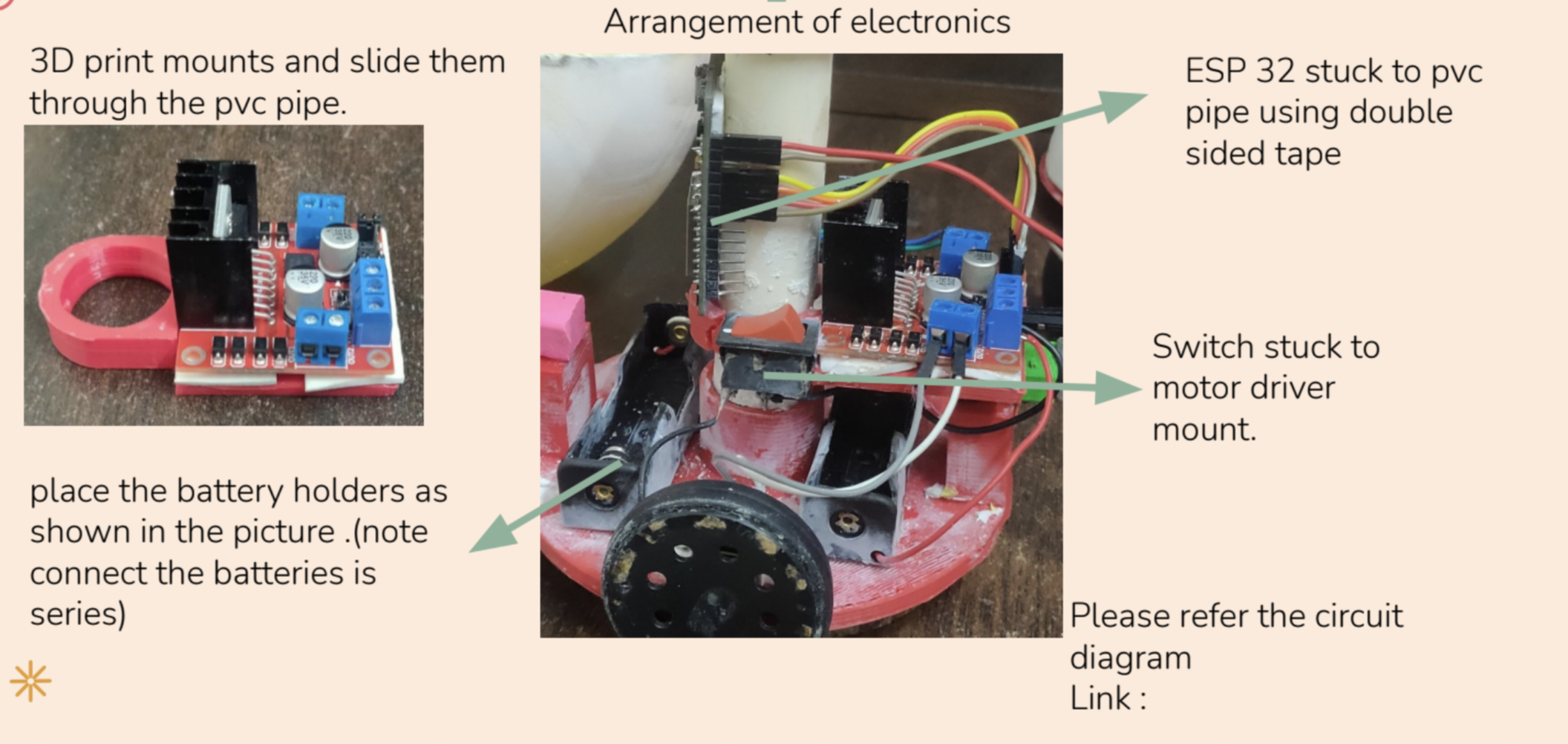
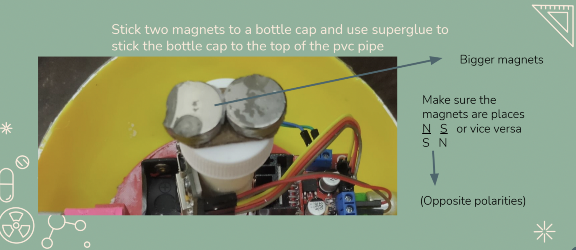
- Fit the Geared motor on 3D printed base by using standard N20 mounting brackets.
- Take 2 castor wheels and fix them using erasers. Ensure the castor wheel is touching the ball surface.
- Mount Motor Driver, ESP32 and other electronics as shown in picture. Do the Connections as circuit diagram.
- Stick the magnets (i have used neodym magnets to ensure better force. But you can try any magnet which is strong enough to hold the head.
Note: Run the base assembly once outside before closing the ball as its a tedious process.
Head Assembly
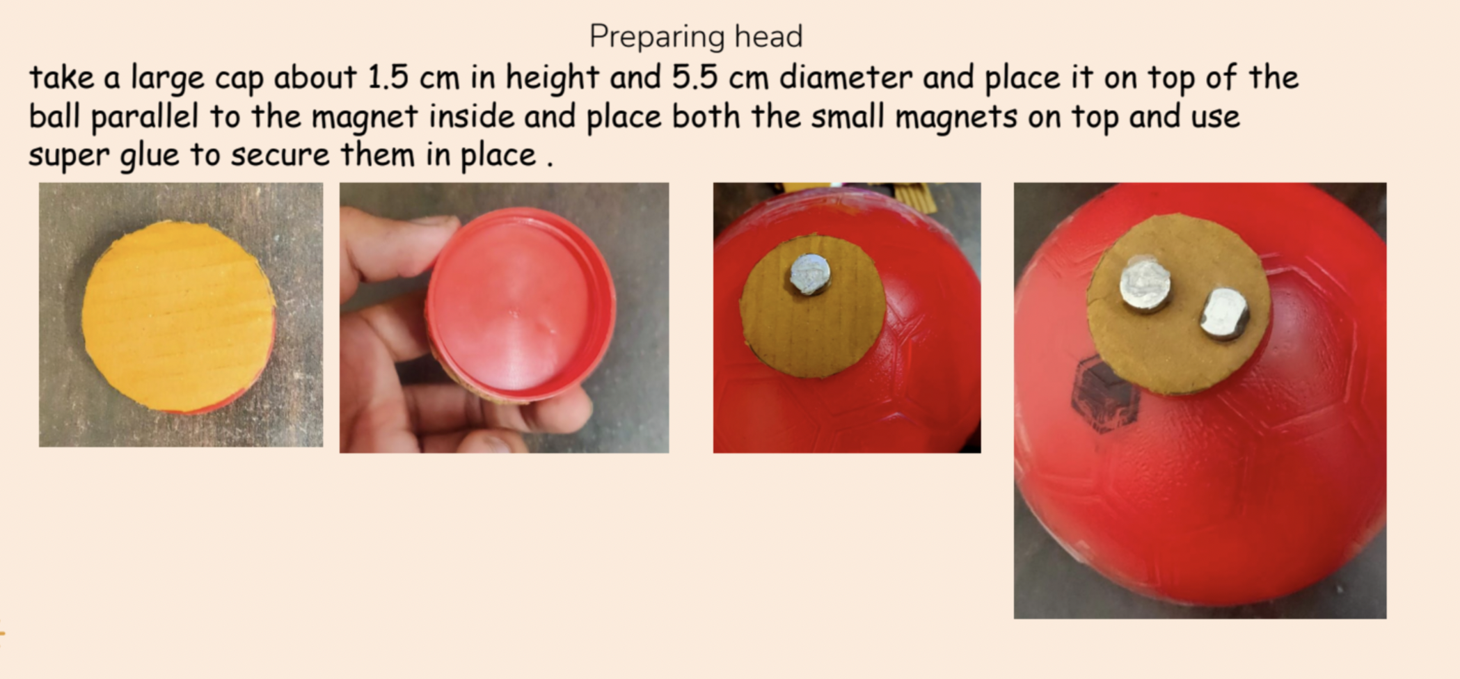
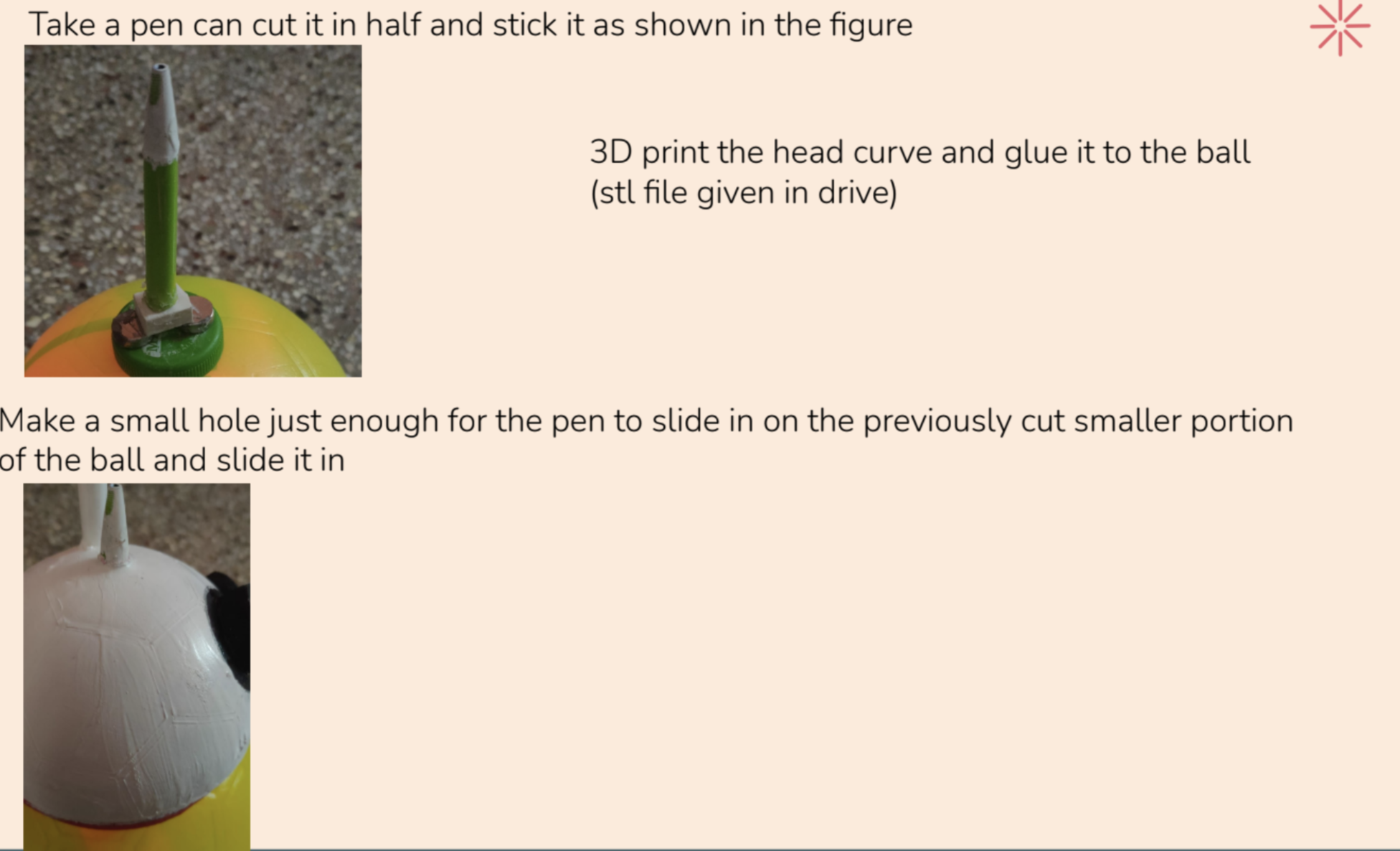
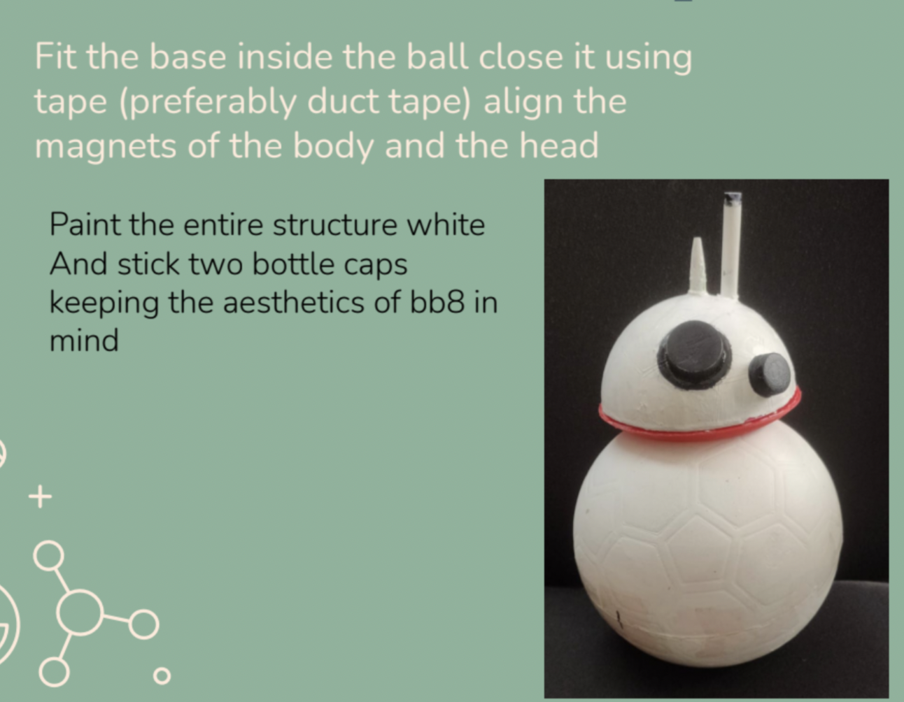
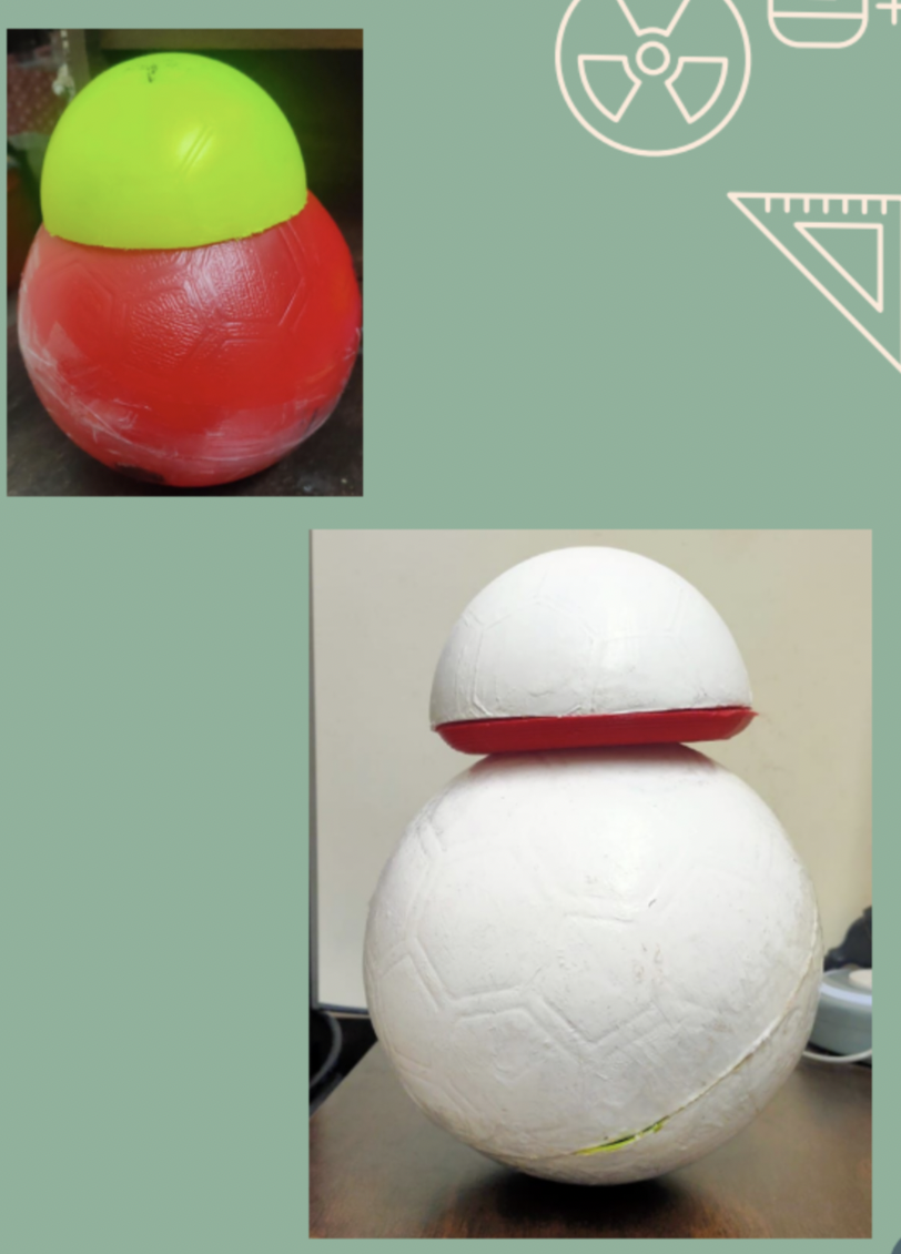
Head Assembly is not having any electronics. It just house magnets and styling parts. Ensure you do not increase the weight of head
- Take the ball which is 2/3 or half the dia of main ball body.
- cut it into two half and use one for head
- Fix a pencil on a bottle cap as shown in picture and video or get the right gap b/w magnet and surface
- Fix the magnet on head and you are good to go
I have used the normal white paint but either you can use the below mentioned stickers on can use dual extrusion printer to get the orange and white style. My Ultimaker #d printer is under breakdown so managing with white paint ans stickers
Code for ESP-32
Here is the code i have used to make control the robot. Setup of ESP32 and code explanation is out of scope for this project. I have used standard Mobile app - created over MIT App inventor for this purpose. also you can use this standard app for quick turn around of your project
 // ESP32 two wheel car control

//ESP32 BB8 driving

//yolabs BB8

#include "BluetoothSerial.h"


BluetoothSerial SerialBT;


char receivedChar;

const int MR1 = 26; //ESP32 pins (MR=Right Motor) (ML=Left Motor) (1=Forward) (2=Backward)

const int MR2 = 27;

const int ML1 = 14;

const int ML2 = 12;


void setup() {

  Serial.begin(115200);

  SerialBT.begin("ESP32_YoLabs_BB-8");

  pinMode(MR1, OUTPUT);

  pinMode(MR2, OUTPUT);

  pinMode(ML1, OUTPUT);

  pinMode(ML2, OUTPUT);

}


void Forward(){

      //RIGHT MOTOR

      digitalWrite(MR1,HIGH);//MOVE FRONT

      digitalWrite(MR2,LOW); //MOVE BACK

      //LEFT MOTOR

      digitalWrite(ML1,LOW);//MOVE BACK

      digitalWrite(ML2,HIGH);//MOVE FRONT

}

void Backward(){

      digitalWrite(MR1,LOW);

      digitalWrite(MR2,HIGH);

      digitalWrite(ML1,HIGH);

      digitalWrite(ML2,LOW);

}

void Left(){

      digitalWrite(MR1,HIGH);

      digitalWrite(MR2,LOW);

      digitalWrite(ML1,HIGH);

      digitalWrite(ML2,LOW);

}

void Right(){

      digitalWrite(MR1,LOW);

      digitalWrite(MR2,HIGH);

      digitalWrite(ML1,LOW);

      digitalWrite(ML2,HIGH);

}

void Stop(){

      digitalWrite(MR1,LOW);

      digitalWrite(MR2,LOW);

      digitalWrite(ML1,LOW);

      digitalWrite(ML2,LOW);

}

void loop() {

    receivedChar =(char)SerialBT.read();


  if (Serial.available()) {

    SerialBT.write(Serial.read());


  }

  if (SerialBT.available()) {


    Serial.print ("Received:");//print on serial monitor

    Serial.println(receivedChar);//print on serial monitor


    if(receivedChar == 'F')

    {

      Forward();


    }

    if(receivedChar == 'B')

    {


      Backward();

    }

     if(receivedChar == 'L')

    {


      Left();

    }

    if(receivedChar == 'R')

    {


      Right();

    }

    if(receivedChar == 'S')

    {

      Stop();

    }

  }

  delay(20);

}