Avoid Workpiece Defects When Laying Out Parts
by SeanMakes in Workshop > CNC
513 Views, 2 Favorites, 0 Comments
Avoid Workpiece Defects When Laying Out Parts
Suppose you need to cut some parts on your CNC and you also want to make the most of some scrap material. This tutorial shows you how to layout your tool paths while avoiding defects in your workpiece. Carbide Create is shown in this demo but I'm sure other CNC programs have a similar feature.
Supplies
- Workpiece you want to use for parts
- Object with a precise length like a rule, 123 block, or caliper set to a known value, etc.
- Smart phone or camera
Measure Your Workpiece
Measure the length and width of your workpiece. You will need these dimensions in a later step. In this demo our workpiece is 21.375 inches by 5.5 inches.
Take a Picture!
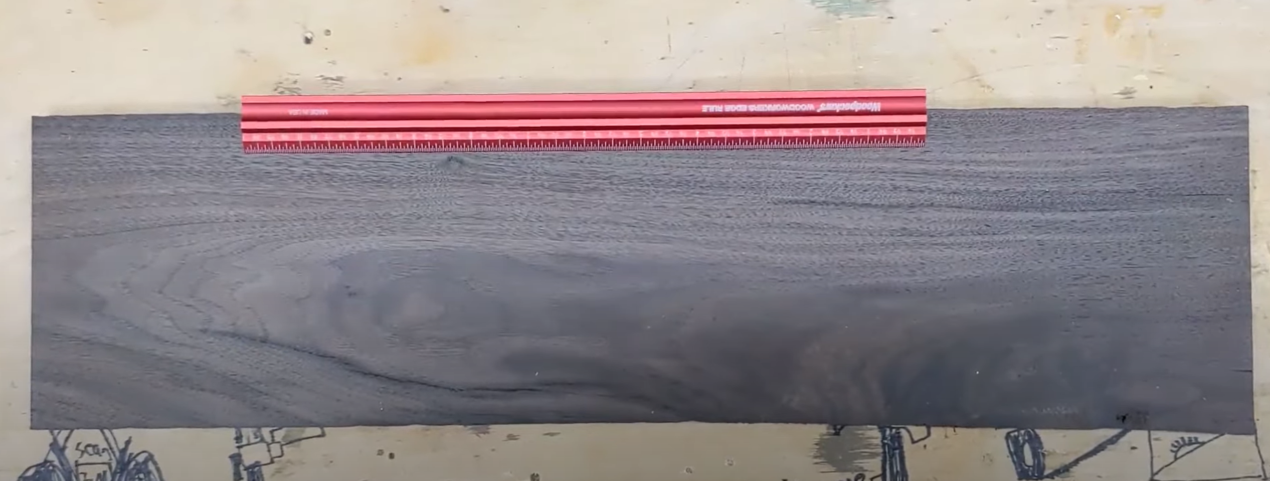
Place an object of known length on your workpiece. For this demo we are using a 12 inch rule. Then take a picture while holding your phone or camera as square and level as possible.
Set Work Area Size to Workpiece Dimensions
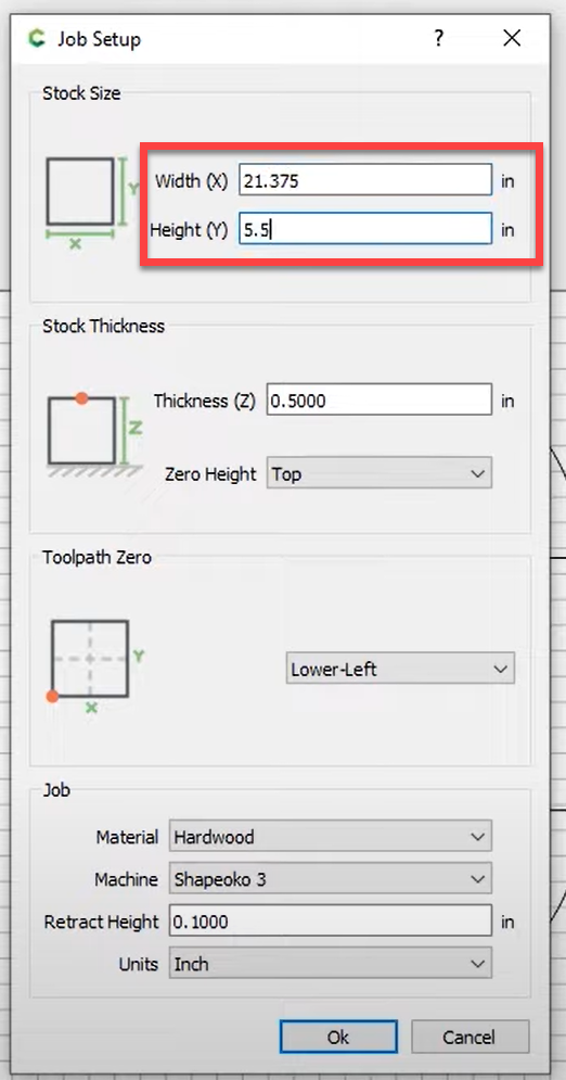
In Carbide Create, set your work area to the same size as your workpiece dimensions that you measured in step 1.
Load Image Into CNC Software
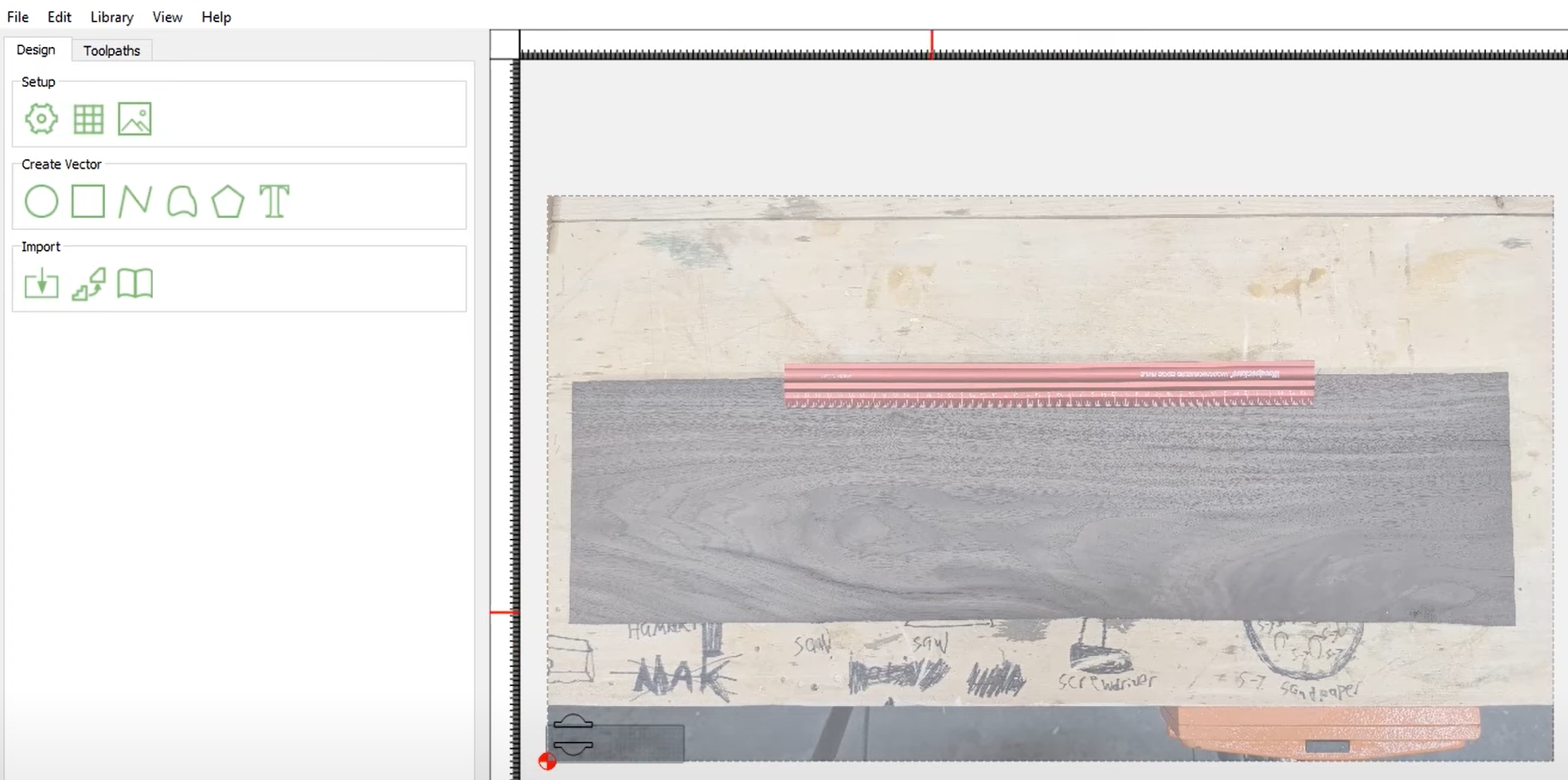
Carbide Create has a feature that allows you to set an image as the background in the drawing editor. Import the image you just captured with your phone.
Measure Image
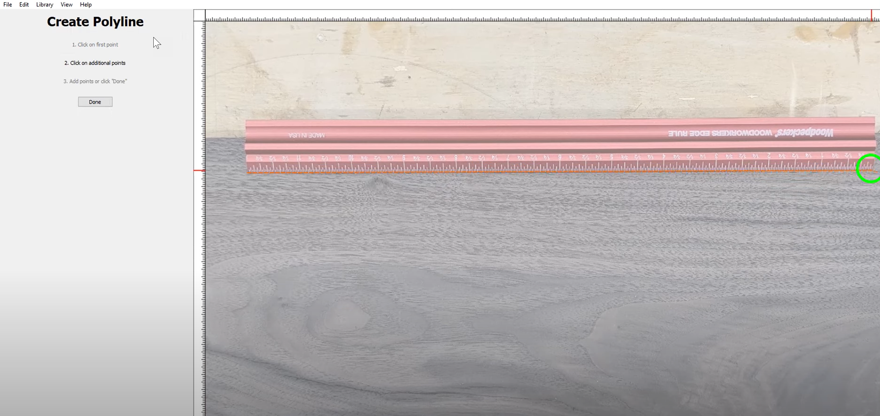
The image will be really large and will need to be scaled down to actual size. First you need to measure the rule in the image. You can use the built in coordinate system two different ways to do this:
- One method is to align the image so that the bottom left corner of the rule is at (0,0) in the drawing. Then zoom in on the lower right corner of the rule and mouse over that corner. Use the coordinates on the lower left to capture the size of the rule inside the editor. For this example we will assume that the rule measures 83.0788 inches inside Carbide Create.
- The other method is to draw a line over the rule from corner to corner. Be as precise as possible when drawing the line. Then use the scale feature to capture the length of the line you just drew. Again, we'll use 83.0788 inches for this demo.
Calculate Scale Factor
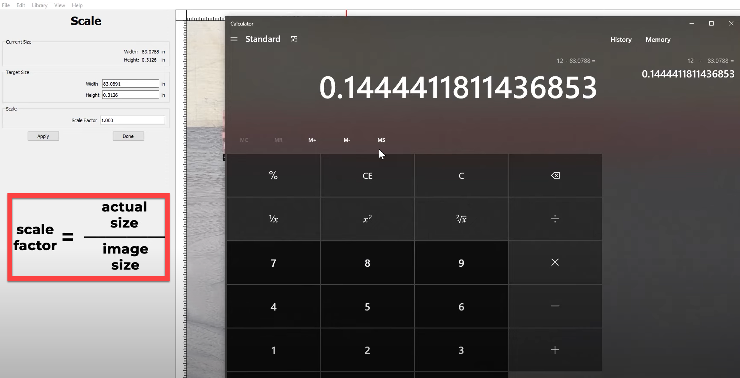
Calculate the scale factor using this simple equation:
- Scale factor = Actual size of the rule ÷ Size of the rule in Carbide Create
- Scale factor = 12 inches ÷ 83.0788 inches
Using this equation our scale factor is: 0.1444
Scale Image and Align to Origin
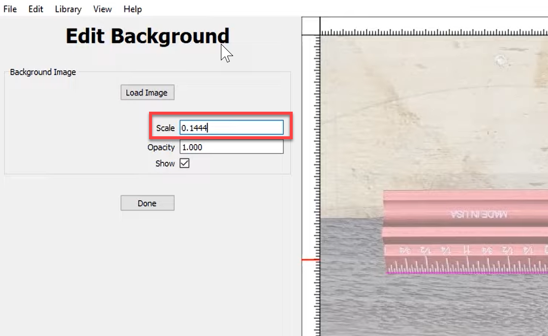
Use the scale feature on the background image to scale the image to actual size. After that make sure the lower left corner of the workpiece is aligned with (0,0) in the drawing editor.
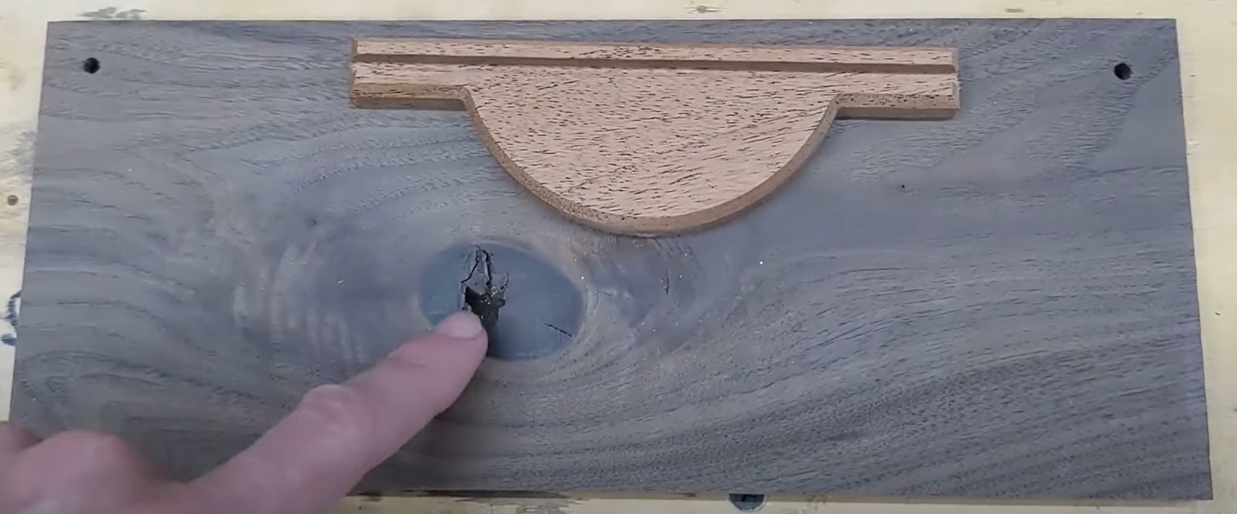
Layout Parts and Create Cutting Paths
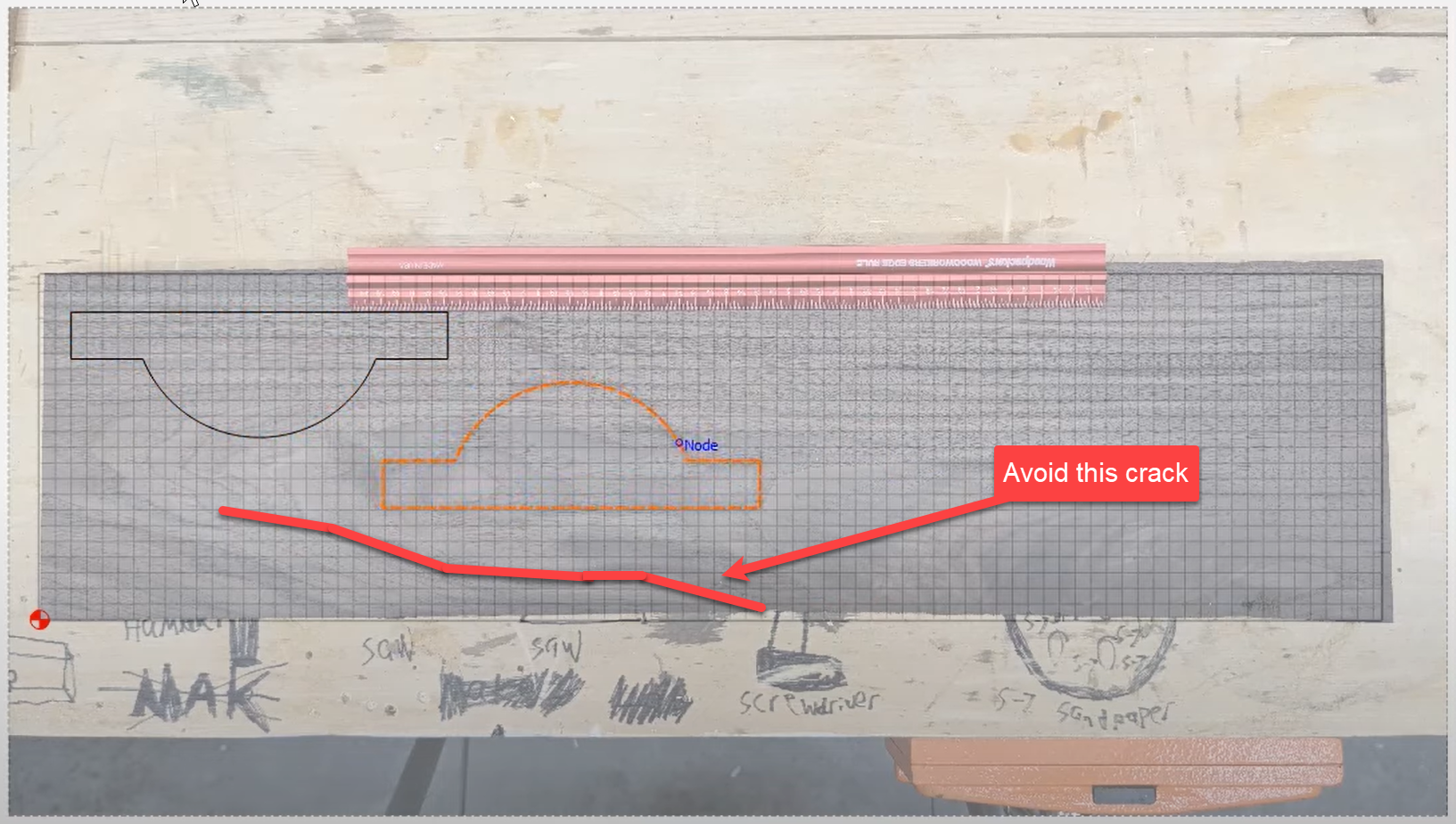
At this point you can layout your parts and create your tool paths as you normally would while avoiding any knots or cracks in your workpiece!
Watch the Demo!
Please watch my demo video that shows two examples of this technique using Carbide Create!