Automating RF Controlled Outlets With Webthings Rules
by Brandon Wood in Circuits > Arduino
1584 Views, 10 Favorites, 0 Comments
Automating RF Controlled Outlets With Webthings Rules
Have you ever wished that appliances would turn on as if by magic at certain times of day, certain days of the week or when you return home? Well for the past three years this has been a regular occurrence in my life thanks to some microcontrollers and the Webthings Project. Today I am going to share with you how I achieved this. I will explain how to get started yourself, and discuss what I learned along the way to help you avoid some of the common pitfalls with home automation.
This Instructable is a guide for using generic RF controlled lights and residential outlets with a microcontroller using RF transmitters and receivers by replaying RF signals. The system I use takes things a step further by making the microcontroller an RF to Wifi Bridge using Webthings Gateway--allowing control or automation of the RF signals using an intuitive self-hosted Web Interface.
Parts Required
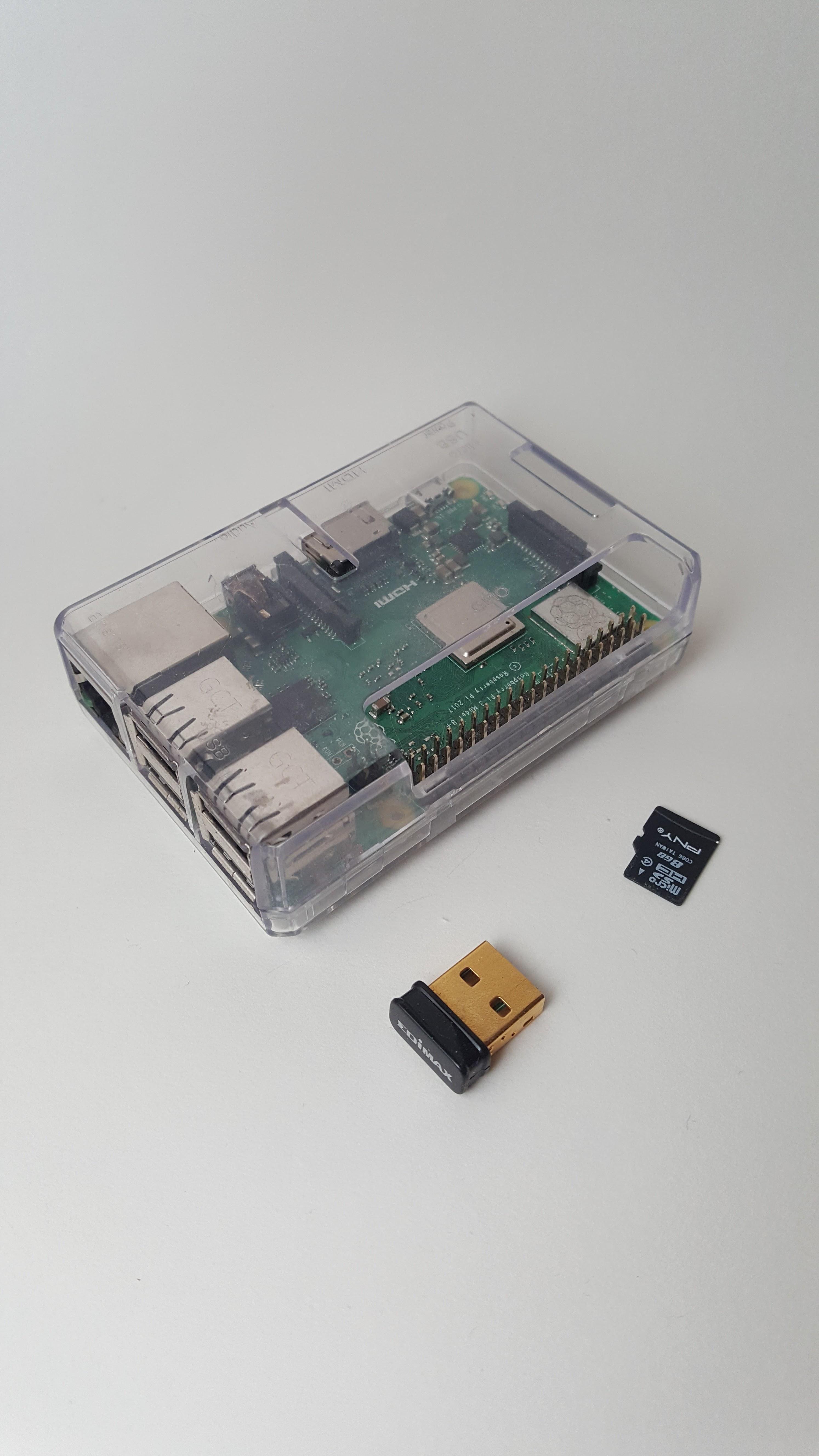
- A modern Raspberry Pi A or B Model. ( http://ebay.us/6NKQuN )
- An SD Card for your Raspberry Pi with at least 8gb of space.
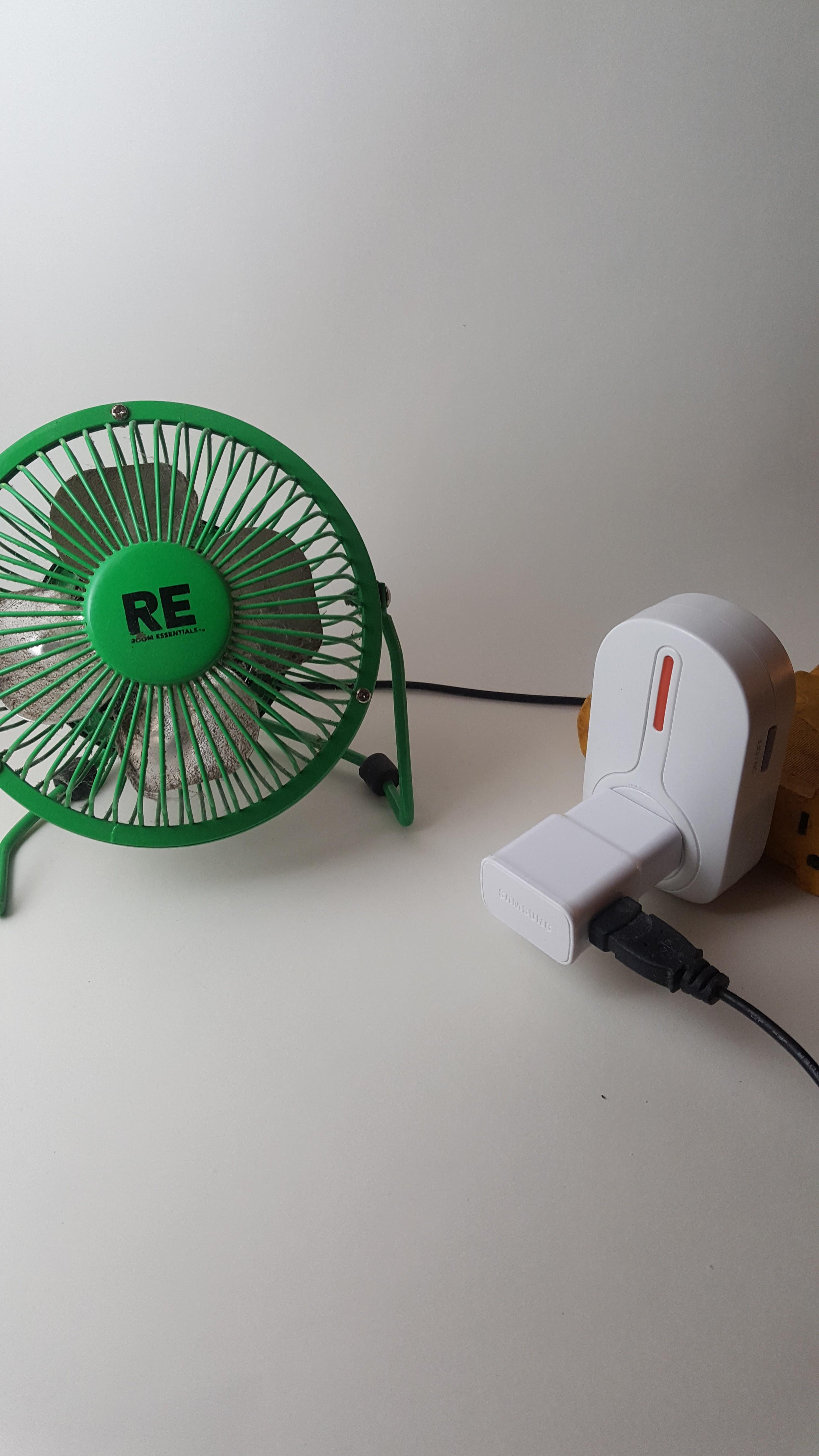
- 2X USB AC power supplies. Commonly known as “Wallwarts”.
- Two micro USB-B to USB to power the Arduino and Raspberry pi.
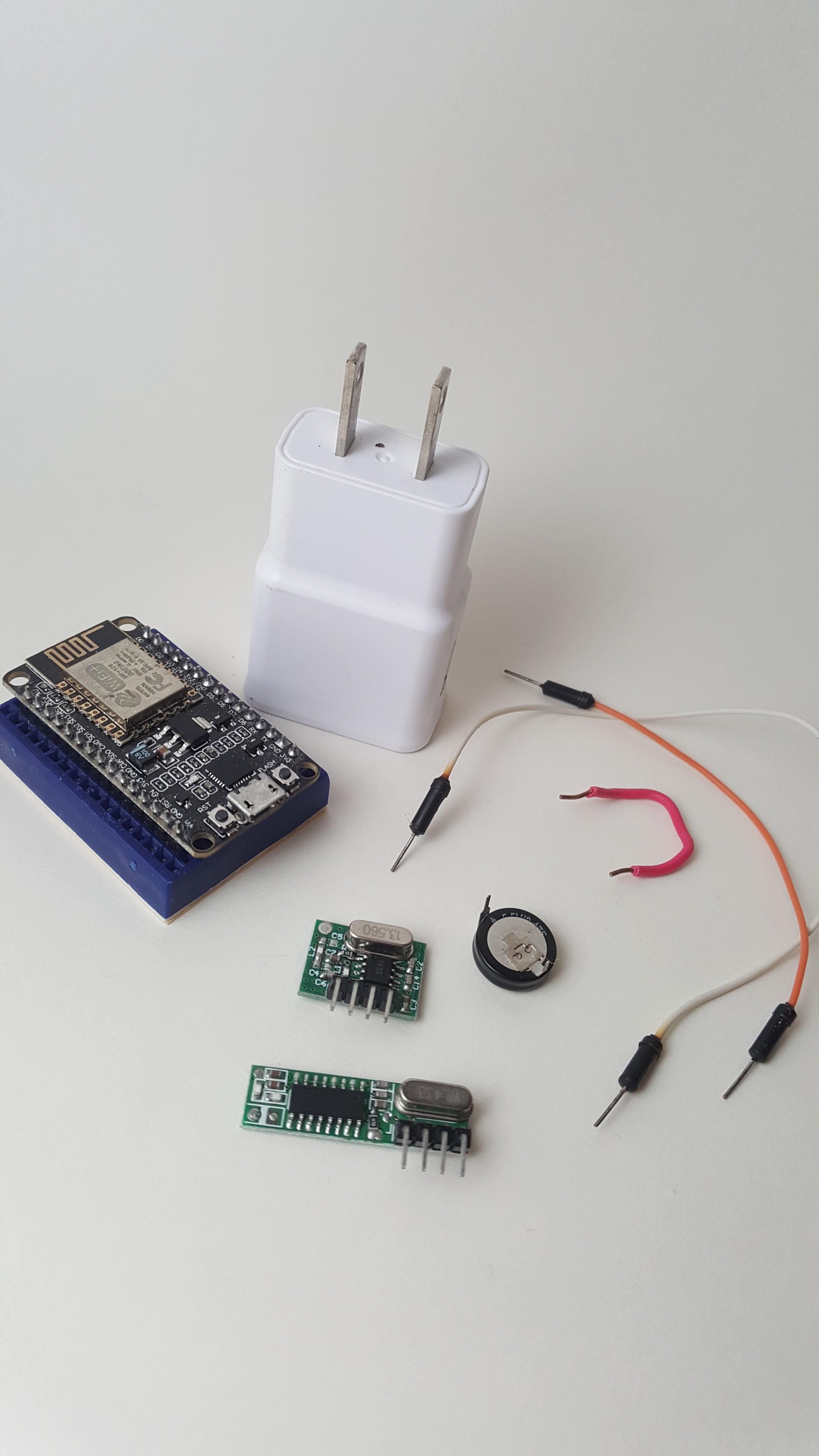
- A NodeMCU ESP-8266 (or similar Wifi enabled arduino model with a 5v output and 2 GPIO pins.) ( http://ebay.us/n3wYkm )
- 433 RF Transmitter and Receiver modules. ( http://ebay.us/ciTsKB )
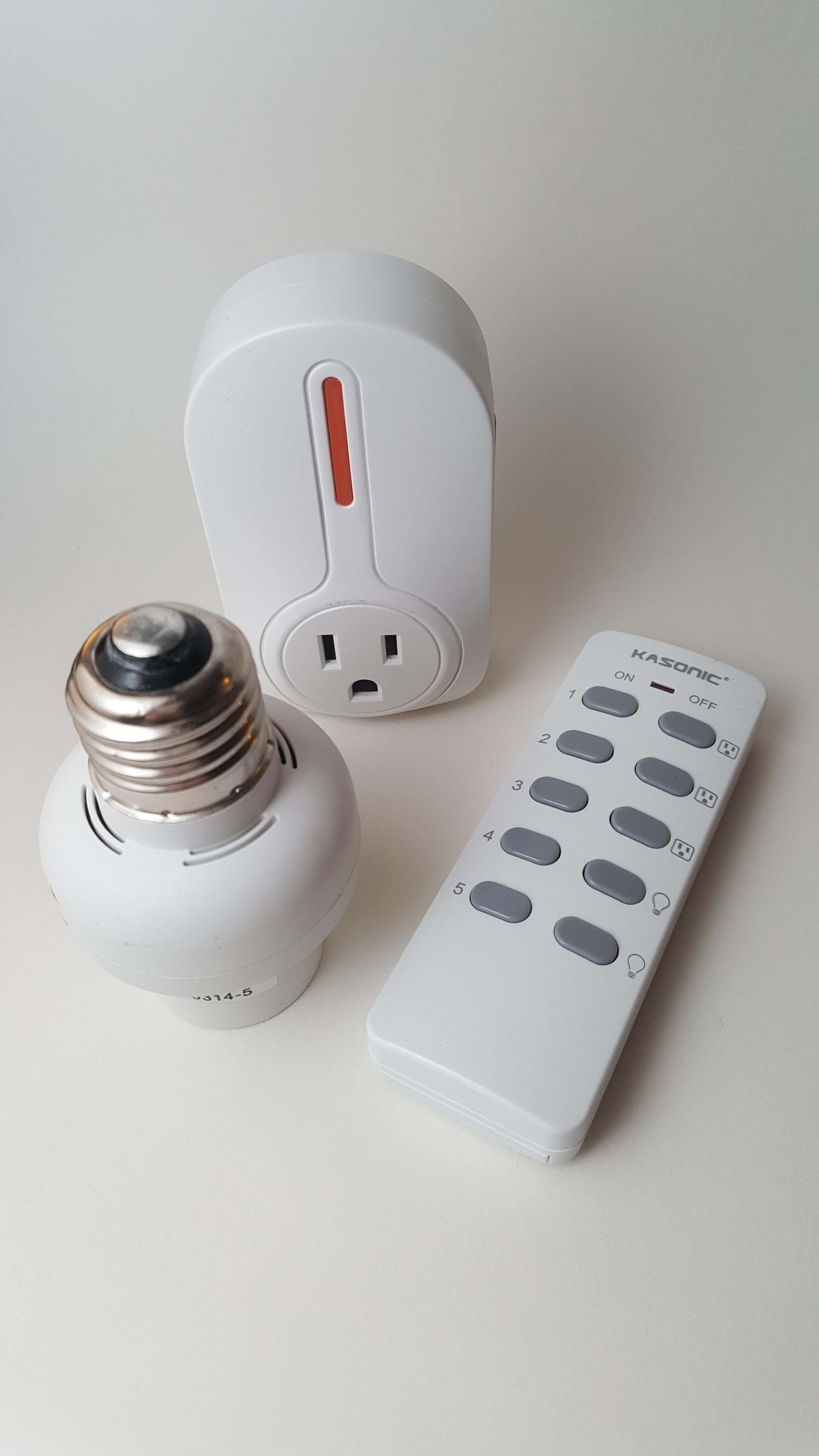
- 433 RF controlled light switches and outlets set. ( http://ebay.us/EhttsZ )
- Optionally a mini breadboard as it’s simpler than soldering. You can buy a multi-pack here: http://ebay.us/LqTtEi. Some short jumper wires.
- Optional, 5v Capacitor.
Recording RF Controller Codes for Parroting Part 1
I assume that you already have some familiarity with Arduino and the paired IDE, if you are not familiar please see this link to install a guide: https://www.arduino.cc/en/guide/windows
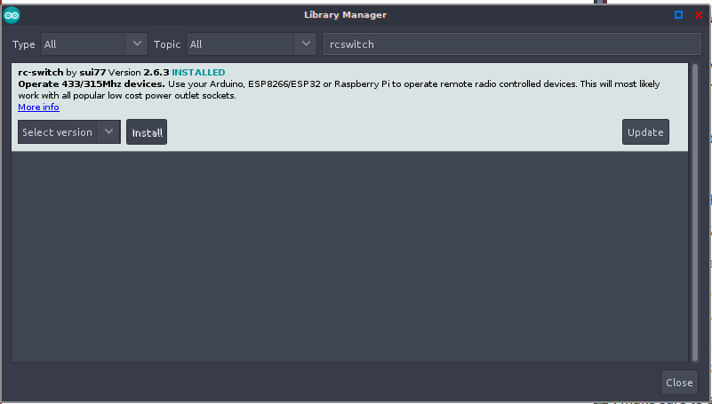
We will be recording the RF commands that the RF remote broadcasts to control the lights or outlets, using the receiver module. We will then retransmit them with the transmitter and thus control the lights with our microcontroller. In order to do this we will leverage the RCswitch library. Please search your Arduino IDE, under Sketch> Include Library> Manage Libraries, then search for RCSwitch and install that library.
Next you will need to plug the NodeMCU into the PC and upload the below code. This code also exists in the examples section of your Arduino IDE after the RCSwitch library is installed.
Receiver Code
/*
  Example for receiving
  <a href="https://github.com/sui77/rc-switch/"> https://github.com/sui77/rc-switch/</a>
  If you want to visualize a telegram copy the raw data and
  paste it into <a href="http://test.sui.li/oszi/"> https://github.com/sui77/rc-switch/</a>
*/

#include <rcswitch.h></rcswitch.h>RCSwitch
mySwitch = RCSwitch();

void setup() {
  Serial.begin(9600);
  mySwitch.enableReceive(9);
}

void loop() {
  if (mySwitch.available()) {
    output(mySwitch.getReceivedValue(),
    mySwitch.getReceivedBitlength(),
    mySwitch.getReceivedDelay(),
    mySwitch.getReceivedRawdata(),
    mySwitch.getReceivedProtocol());
    mySwitch.resetAvailable();
  }
}
Recording RF Controller Codes for Parroting Part 2
I am assuming you already have NodeMCU Libraries installed, if not please follow this tutorial:
https://www.instructables.com/Steps-to-Setup-Ardui...
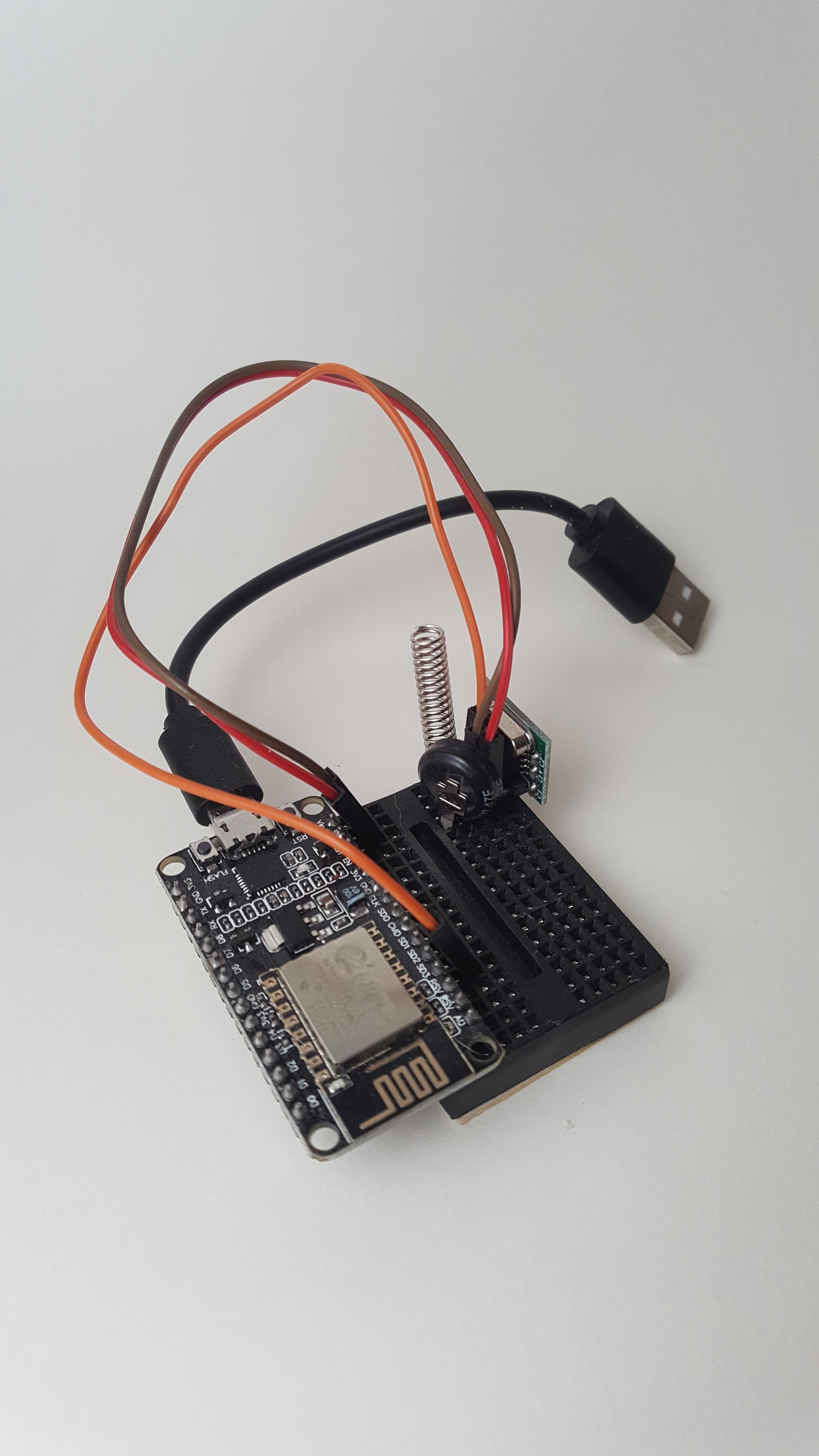
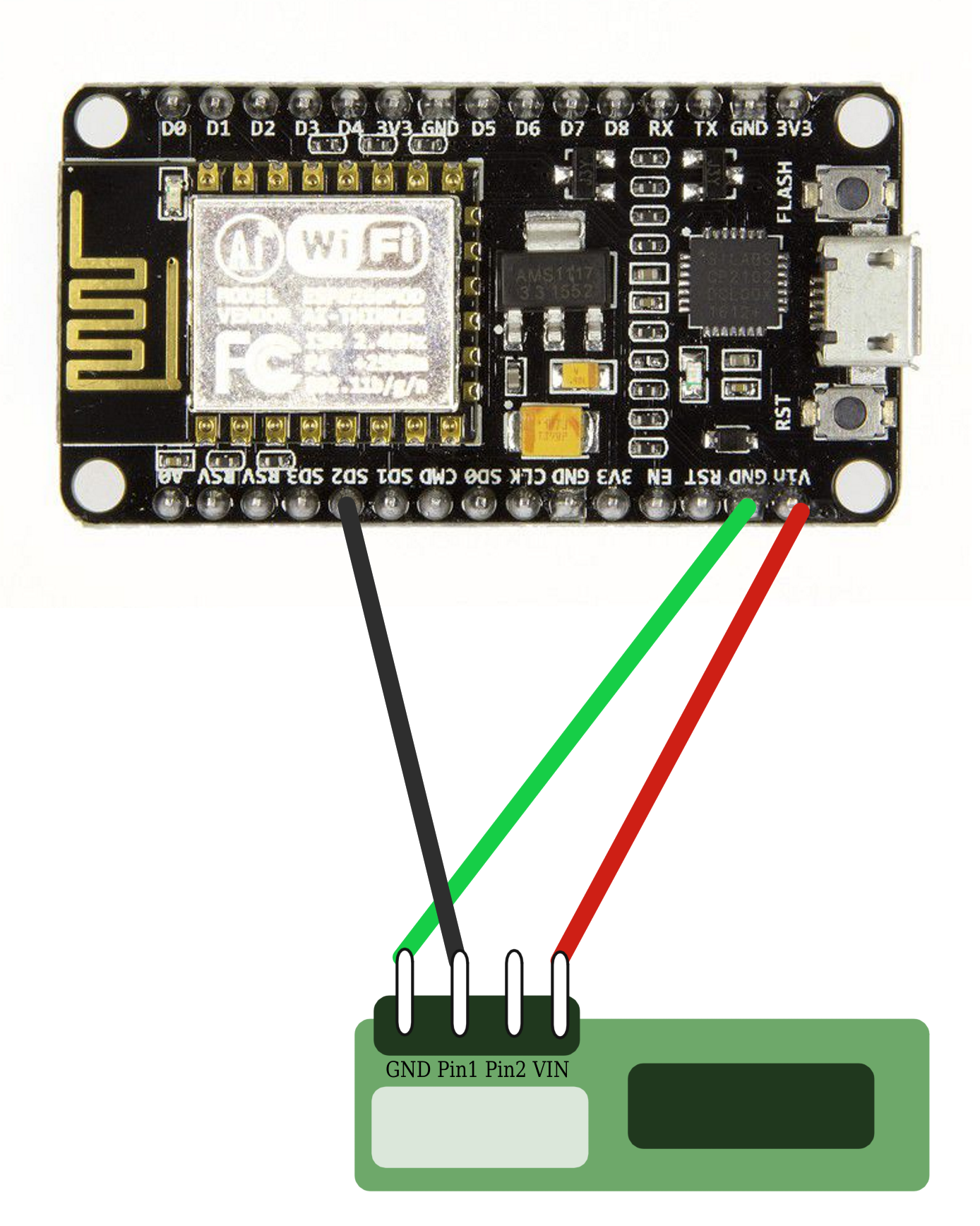
Next you will need to wire your receiver to your NodeMCU using the below configuration. For this use case you probably will not require an antenna or additional 5v capacitor. Now while the NodeMCU is connected to your PC open up your Serial Monitor, under Tools> Serial Monitor. Then you need to press each of the buttons on your RF Remote, you should see RF Codes and associated with the presses appear in the Serial Monitor. Take note of these values for the next step.
Testing RF Controller Codes
Before continuing onto the next steps let’s try a very simple test for the controllers. While your NodeMCU is unplugged please wire up the Transmitter according to the schematic above. I have attached a test snippet below from the RCSwitch library, you will see that there are many different formats of Codes in the Loop section, your Codes from the previous step should match one type of these and you can remove the others. You may additionally need to configure the Pulselength value in settings. Then you will need to replace a set of values in this snippet with your Codes. You only need two for a good test, the on and the off of a single light is a good test.
Upload this test snippet to your NodeMCU and then off using the related codes to validate functionality. Note: Your board may come with an external antenna and antenna pin, I found that without the antenna attached to the Antenna Solder Joint and a 5V Capacitor in series with VCC I could not get the RF frequencies to work properly.
Controller Test Code
/*
  Example for different sending methods
  <a href="https://github.com/sui77/rc-switch/"> https://github.com/sui77/rc-switch/</a>
*/


#include <rcswitch.h></rcswitch.h>
RCSwitch mySwitch = RCSwitch();

void setup() {
  Serial.begin(9600);
  // Transmitter is connected to Arduino Pin #10
  mySwitch.enableTransmit(10);
  // Optional set protocol (default is 1, will work for most outlets)
  // mySwitch.setProtocol(2);
  // Optional set pulse length.
  // mySwitch.setPulseLength(320);
  // Optional set number of transmission repetitions.
  // mySwitch.setRepeatTransmit(15);
}

void loop() {
  /* See Example: TypeA_WithDIPSwitches
  mySwitch.switchOn("11111", "00010");
  delay(1000);
  mySwitch.switchOff("11111", "00010");
  delay(1000);
  */

  /* Same switch as above, but using decimal code
  mySwitch.send(5393, 24);
  delay(1000);
  mySwitch.send(5396, 24);
  delay(1000);
  */

  /* Same switch as above, but using binary code */
  mySwitch.send("000000000001010100010001");
  delay(1000);
  mySwitch.send("000000000001010100010100");
  delay(1000);

  /* Same switch as above, but tri-state code
  mySwitch.sendTriState("00000FFF0F0F");
  delay(1000);
  mySwitch.sendTriState("00000FFF0FF0");
  delay(1000);
  */


  delay(1000);
}
Installing Webthings Gateway
Please follow the below link to download the official, latest Webthings Gateway Image from the link below: https://webthings.io/gateway/
And Flash it onto your 8gb SD Card using Etcher which can be downloaded here: https://www.balena.io/etcher/
Then finally insert it into your Raspberry Pi, boot it up, connect it to Wifi and run through the installer. Further details can be found at the official Webthings Gateway documentation: https://webthings.io/docs/gateway-getting-started...
There are three main reasons I continue to use ‘Webthings’ over something like OpenHabb or Google Home:
1) It’s completely self hostable without any internet connection.
2) It has great integration with Arduino and Python.
3) It has so many awesome add-ons that just keep getting better as it develops.
Upload Webthings Code to NodeMCU
The next thing you will need to do is install the latest Arduino Webthings Library, you can navigate to their Github and download their latest release as a ZIP file. Once you do that, navigate to your Arduino IDE, Sketch> Include Library > Add ZIP Library and select your downloads zip.
Documentation: https://github.com/WebThingsIO/webthing-arduino
Download: https://github.com/WebThingsIO/webthing-arduino/r...
Below is the code that I used, you will need to replace the wifi configuration and RF Codes with those discovered in the previous step:
Code for Nodemcu Webthing Bridge
/*
 * Mozilla Webthings RF Smart Switch Example
 * By Brandon T. Wood
 */
#include
#include "Thing.h"
#include "WebThingAdapter.h"
#include

const char* ssid = "";
const char* password = "";
const int ledPin = LED_BUILTIN;
WebThingAdapter* adapter;
RCSwitch mySwitch = RCSwitch();
const char* codes[] = {
    "010000000101010100110011",
    "010000000101010100111100",
    "010000000101010111000011",
    "010000000101010111001100",
    "010000000101011100000011",
    "010000000101011100001100",
    "010000000101110100000011",
    "010000000101110100001100",
    "010000000111010100000011",
    "..."
};

int lengths[] = {
  166,
  166,
  167,
  167,
  167,
  166,
  166,
  167,
  166,
  167
};

const char* ledTypes[] = {"OnOffSwitch", "Light", nullptr};

ThingDevice led9("led9", "Built-in LED", ledTypes);
ThingDevice led10("led10", "Built-in LED", ledTypes);
ThingDevice led11("led11", "Built-in LED", ledTypes);
ThingDevice led12("led12", "Built-in LED", ledTypes);
ThingDevice led13("led13", "Built-in LED", ledTypes);

ThingProperty led9On("on", "", BOOLEAN, "OnOffProperty");
ThingProperty led10On("on", "", BOOLEAN, "OnOffProperty");
ThingProperty led11On("on", "", BOOLEAN, "OnOffProperty");
ThingProperty led12On("on", "", BOOLEAN, "OnOffProperty");
ThingProperty led13On("on", "", BOOLEAN, "OnOffProperty");

bool lastOn1 = false;
bool lastOn2 = false;
bool lastOn3 = false;
bool lastOn4 = false;
bool lastOn5 = false;

void setup(void){

  mySwitch.enableTransmit(10);
  Serial.begin(115200);
  Serial.println("");
  Serial.print("Connecting to \"");
  Serial.print(ssid);
  Serial.println("\"");
  WiFi.mode(WIFI_STA);
  WiFi.begin(ssid, password);
  Serial.println("");
  // Wait for connection
  bool blink = true;
  while (WiFi.status() != WL_CONNECTED) {
    delay(500);
    Serial.print(".");
    digitalWrite(LED_BUILTIN, blink ? LOW : HIGH); // active low led
    blink = !blink;
  }
  digitalWrite(LED_BUILTIN, LOW); // active low led

  Serial.println("");
  Serial.print("Connected to ");
  Serial.println(ssid);
  Serial.print("IP address: ");
  Serial.println(WiFi.localIP());

  // Change this below value for each new switch on your network.
  adapter = new WebThingAdapter("w27", WiFi.localIP());

  led9.addProperty(&led9On);
  led10.addProperty(&led10On);
  led11.addProperty(&led11On);
  led12.addProperty(&led12On);
  led13.addProperty(&led13On);

  adapter->addDevice(&led9);
  adapter->addDevice(&led10);
  adapter->addDevice(&led11);
  adapter->addDevice(&led12);
  adapter->addDevice(&led13);
  adapter->begin();

  Serial.println("HTTP server started");

  Serial.print("http://");
  Serial.print(WiFi.localIP());
  Serial.print("/things/");
  Serial.println(led9.id);

  Serial.print("http://");
  Serial.print(WiFi.localIP());
  Serial.print("/things/");
  Serial.println(led10.id);

  Serial.print("http://");
  Serial.print(WiFi.localIP());
  Serial.print("/things/");
  Serial.println(led11.id);

  Serial.print("http://");
  Serial.print(WiFi.localIP());
  Serial.print("/things/");
  Serial.println(led12.id);

  Serial.print("http://");
  Serial.print(WiFi.localIP());
  Serial.print("/things/");
  Serial.println(led13.id);
}

void loop(void){
  adapter->update();
  bool on1 = led9On.getValue().boolean;
  bool on2 = led10On.getValue().boolean;
  bool on3 = led11On.getValue().boolean;
  bool on4 = led12On.getValue().boolean;
  bool on5 = led13On.getValue().boolean;

  //digitalWrite(LED_BUILTIN, HIGH);

  if (on1 != lastOn1){
    mySwitch.setPulseLength(lengths[9]);
    mySwitch.send(on1 ? codes[0] : codes[1]);
    Serial.print(led9.id);
    Serial.print(": ");
    Serial.println(on1);
  }

  if (on2 != lastOn2){
    mySwitch.setPulseLength(lengths[4]);
    mySwitch.send(on2 ? codes[2] : codes[3]);
    Serial.print(led10.id);
    Serial.print(": ");
    Serial.println(on2);
  }

  if ( on3 != lastOn3 ){
    mySwitch.send(on3 ? codes[4] : codes[5]);
    Serial.print(led11.id);
    Serial.print(": ");
    Serial.println(on3);
  }
  if (on4 != lastOn4) {
    mySwitch.send(on4 ? codes[6] : codes[7]);
    Serial.print(led12.id);
    Serial.print(": ");
    Serial.println(on4);
  }
  if (on5 != lastOn5) {
    mySwitch.send(on5 ? codes[8] : codes[9]);
    Serial.print(led13.id);
    Serial.print(": ");
    Serial.println(on5);
  }

  lastOn1 = on1;
  lastOn2 = on2;
  lastOn3 = on3;
  lastOn4 = on4;
  lastOn5 = on5;
}
Configuring Webthings and Automation Rules
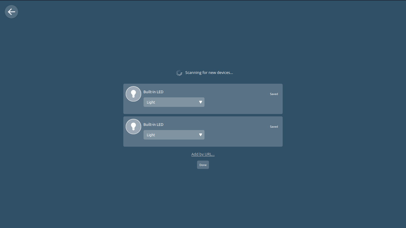
Once you have your NodeMCU running the above Webthings code and your Webthings Gateway running on your Raspberry PI you will need to navigate to your Webthing’s Gateway interface to add your new RF switches. Under the “Things'' tab you will see a small Plus button in the bottom right hand corner, click this and your Lights should be automatically discovered! Simply click add and then save, by clicking on them the RF should power on and off.
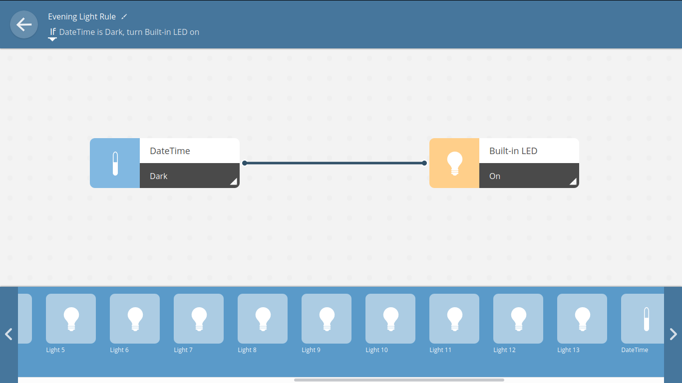
Next we can set up some rules by navigating to the “Rules'' tab and then clicking the Plus icon again. The left section will be the trigger for the rule and the right side will be the effect of the rule. What’s available out of the box is limited, i.e. rules that turn one light off when another is on. You can install a variety of add-ons such as the Datetime add-on that I use to turn lights on at certain times of the day such as when it’s dark out. There are currently add-ons for Weather and many open source integrations!
As of submitting this I have rules set up that turn on our coffee pot ten minutes before we wake up, turning off our lights when our phones are not detected on our network for 10 minutes and powering off all our lights at a certain time of night automatically.
Problems and Future Ideas
This system has worked great for over a year with little issue and I found it a great alternative to messing with relays. Additionally it comes with a remote backup if the system is down. If I had one problem it’s that we sometimes still use the RF remotes for the lights though this desyncs their on/off state from Webthings. I think in the future some sort of robust feedback would be good, but powering the lights off at night is a hacky patch currently.
As for future ideas I would like to see how this system could be expanded to have one low power Arduino control multiple sets of RF lights, maybe 20-30 different ones with different signals. I also have friends who would like to be able to control their IR devices such as their air conditioners with such a bridge as this.
If you end up setting this up yourself please let me know! Post and let everyone see the automation you create with this NodeMCU RF Light controller!