Automatic Smart Light for Homes
by Ayush Goel1 in Circuits > Arduino
262 Views, 0 Favorites, 0 Comments
Automatic Smart Light for Homes

Have you ever been to one of those homes where the light automatically switches on when you enter the room and switches off when you leave? I have and I wanted that light in my house but when I checked the price, I changed my mind. Eventually, my eagerness got the better of me and I decided to make one using Arduino, and I did! Now I am going to show you how to make it as well.(A crude form at least, but it is still exciting to use:)
Supplies
Arduino Uno x 1
PIR (motion sensor) x 1
Relay (to manage the 220V that comes out of the mains) x 1
A couple of jumper cables
Bulb (obviously:) x 1
Wiring


For those of you who like a video format, watch the video above. Everything is the same, except this instructable is more detailed.
Now, the first step is to wire the Arduino with the components. Let's do it one by one.
PIR ----- Arduino
VCC -- 5V
Gnd -- Gnd
OUT -- 2 (Digital Pin)
'OUT' may be labelled as 'In' in some Pir's but it is basically the data pin.
Now that we have the Arduino wired up, let's move on to the relay.
Relay -- Arduino
VCC -- 5V
Gnd -- Gnd
In -- 11 (Digital Pin)
'In' is again the signal given by the Arduino to the relay.
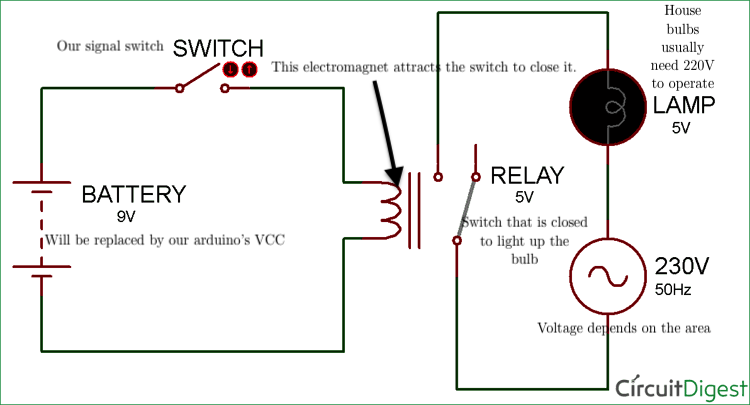
Before we move on, let's understand how a relay switch works.
A relay switch essentially has 2 independent circuits. One of them carries a large current or voltage but needs to be controlled by a smaller device that can't handle that voltage or current. This circuit has a switch that keeps the circuit open until the circuit is given.
The other circuit is an electromagnet that attracts the switch. In other words, it is the device that closes the switch on the signal.
Thanks to CircuitDigest for this image.
So hopefully the image gave you a clearer understanding.
When the relay says 5V Relay on it, it means that it takes 5V supplied through the electromagnet for the switch to close.
Lastly, we need to connect the bulb to the relay.
Firstly, the positive wire of the bulb goes to the 'Normally Open (NO)' port in the relay. Then the 220V which comes from the mains goes to the 'COM' port of the relay. This is generally the centre one. The other end of the 220V wire goes to the live part of the plug and the negative wire of the bulb goes to the other part.
You can check the video for a better understanding of the relay wiring. The reason there is something called 'Normally Closed NC' is that there are actually 3 circuits in the relay that is sold to us. By default, the switch closes one circuit and leaves the other open. When the switch is activated, it closes the other circuit leaving the previous one open. This is useful for applications where current is to be given one way for a given condition and the other way for another condition.
Sorry if I couldn't explain this concept to you properly. (It is my first instructable and I am 15).
Now the wiring is complete! Is it not surprisingly simple?
Coding
Now we want to know when the PIR detects motion and turn on the bulb at that time.
Following is the code that needs to be uploaded to the Arduino Uno:
int bulb = 11; // the pin that the bulb is connected to
int sensor = 2; // the pin that the sensor is atteched to int state = LOW; // by default, no motion detected
int val = 0; // variable to store the sensor status (value)
void setup() {
pinMode(bulb, OUTPUT); // initalize bulb as an output
pinMode(sensor, INPUT); // initialize sensor as an input
Serial.begin(9600); // initialize serial
}
void loop(){
val = digitalRead(sensor); // read sensor value
if (val == HIGH) { // check if the sensor is HIGH
digitalWrite(bulb, 1); Serial.println("Motion detected!");// turn bulb ON
delay(10000); // delay 100 milliseconds
} else {
digitalWrite(bulb, 0); // turn Bulb OFF
delay(100); // delay 200 milliseconds
Serial.println("Motion stopped!");
}
}
The code is simple enough to understand. What we are essentially doing is reading the PIR's output using digitalRead(); The PIR returns HIGH whenever it detects motion, so it practically does everything for us. We then send the signal to the relay using digitalWrite() and then wait for 10 seconds to switch off the bulb.
This is the drawback. I haven't gotten how to use the PIR to detect which direction the motion is in, so I just assumed that you are done with your business in 10 seconds, which doesn't happen in real life. However, this light works well for entrances as on average you spend less than 10 seconds entering the house and keeping your stuff. Plus it surprises your guests:)
ENJOY:)
If you want to install this in your house, just replace the open bulb with your house's tube light or bulb. (Electricians will easily do it for you). To power up the Arduino, you can just use your phone's charging adapter and connect the Arduino's USB cable to that. It works like a charm. Once it is set up, it is really fun to use.
Thanks for reading and I hope you learned something. Please give me feedback as well, since this is only my first instructable.