Automatic Hand Sanitizer Dispenser
by Nikolas Babetas in Living > Health
6868 Views, 28 Favorites, 0 Comments
Automatic Hand Sanitizer Dispenser

.png)
.png)
.png)
Hi friends, in this Instructables I will show you how to make an accessory that can be attached to most hand sanitizer/soap dispensers and make them Completely Automatic and Hands-Free! Firstly though check out the video above to see the device in action and understand how it functions!
My name is Nikolas, I am from Greece and I will go into the 10th Grade this month!
Story
Over the last months the COVID-19 pandemic has been spreading chaos all around the world. There have been countless infections and unfortunately many casualties. One of the most important measures suggested by the World Health Organization is frequent hand washing with either soap or hand sanitizers. But one of the most significant problems is the way we do it and that is by physically touching the dispenser which eliminates the whole purpose of the action and even creates a great risk of infection. So I decided to create something using an Arduino Nano board that could combat this problem, but I also wanted it to be cheap and to be able to be attached to many different dispensers easily, quickly and effectively! And this is exactly what I made, an accessory that can be attached to most hand sanitizer/soap dispensers and turn them Completely Hands-Free and Automatic!
Supplies
Here is the list of things you will need
- 1 x Arduino Nano
- 1 x DRV8825 Bipolar Stepper Motor Driver
- 1 or more x Generic breadboards (I used 2 mini breadboards as they seem to fit the enclosure more easily)
- Many Jumper Wires
- 1 x 28BYJ-48 4 Phase Stepper Motor DC 5V For Arduino (OEM)
- 1 x Infrared Obstacle Avoidance Sensor Module
-
1 x Limit Switch KW12-3 - Micro Roller Lever Arm Normally Open/Close
-
1 x Aluminium Rigid Coupling 5mm to 8mm
-
1 x Trapezoidal Lead Screw T8-300mm with Brass Nut, Pitch 2mm (you will need about 80mm of the screw)
-
1 x On-Off switch (generic)
-
A Hand Sanitizer Dispenser
-
1 x 688zz Ball Bearing 8x16x5mm
-
1 x LM8UU 8x15x24mm Solid Polymer Linear Bearing
-
2 x Velcro ties
-
1 x 9V battery (generic)
-
1 x 9V Battery Clip
-
1 x Resistor 1kΩ
-
1 x Electrolytic Capacitor 100μF
-
19 x M3 Screw any length from 8mm to 20mm
-
A 3D printer (If you don't have access to one you could try using wood or cardboard instead)
- A stapler
-
A Soldering Iron (generic)
-
Software
-
Arduino IDE
-
3D Slicer ( I would suggest Cura)
Understand the Mechanism
.png)
.png)
So basically a stepper motor is connected with a coupler to a screw. The 3D printed Presser is connected on one side with the screw using a nut and on the other side it is supported by a 3D printed rod. The rod does not allow the screw's rotational force to rotate the presser and instead the presser moves linearly. This way we can command the stepper to move in any direction (back and forth), at any speed and for as many steps as we like.
Understand How the Device Works
.png)
.png)
.png)
.png)
The concept is that when the IR Obstacle Sensor, which is attached to the 3D printed IR Holder, gets activated, by simply putting your hand a few centimetres (inches) below it, the presser goes down a set distance, (pressing the dispenser) waits for 2 seconds and then returns to the initial position by simply going up until the end-stop switch gets activated. Similarly when the device first gets powered on, the presser will go up until the switch gets activated and then it stops there, as a kind of self-calibration so that the presser is ready for use. Then using the Velcros you wrap the Hand-Sanitizer of your choice and tighten it as much as possible.
Now the Automatic Hand Sanitizer Dispenser is completely functional!
Design Custom Parts
.png)
.png)
.png)
.png)
.png)
.png)
.png)
.png)
All the 3D printed parts were designed by me on Onshape but you don't need to worry about 3D designing because I have provided all the necessary .stl files!
3D Printing Custom Plastic Parts
.png)
.png)
.png)
.png)
.png)
.png)
I 3D printed the parts on my Creality3D Ender 3 V2 Printer in Grey and White PLA at 0.2mm layer height and at 20% infill. If you don't have access to a 3D printer don't worry you could always try using cardboard or wood.
Modding the Stepper
.png)
.png)
.png)
.png)
The 28BYJ-48 stepper motor is a small and really cheap unipolar stepper motor and has a torque of about 300 g/cm which works with our project but I wanted it to be stronger for better results. We can increase the torque to 800+ g/cm by converting it to a bipolar motor with a simple and easy mod! This is because bipolar steppers have bigger coils and as a result a lot more torque.
- Firstly you want to remove the blue cover with a screwdriver.
- Once removed you want to fully cut off the middle copper trace that goes up to the red wire using a knife. You want to make sure that it does not connect at all anymore.
- Now you can cut off and remove the red wire from both sides.
- You can reattach the blue cover now, if you want. I needed to cut off 2 of its supports to be able to put it back.
Now you have your own bipolar 28BYJ-48 stepper. It has approximately 2.5 times the initial torque. However now you will need to get a bipolar stepper driver such as the DRV8825 which I am using. The minimum voltage supply for the driver is rated at 8.4V and our motor is rated at only 5V. But don't worry the bipolar version of the motor can easily handle that voltage!
DIY Velcro Ties
.png)
.png)
.png)
.png)
It's time to make the Velcro ties that will attach the accessory to the dispenser! If you already have some Velcro cable ties feel free to use them. Otherwise cut one part at 30cm - 40cm and the other at 4cm - 7cm, you can make them as short or as long as you like. Now you want to staple the two parts together. Make sure that the sides that will be stapled together are either both rough or both soft. Now your Velcro tie is ready to use! You will need two of these.
Circuit
.png)
.png)
.png)
.png)
.png)
.png)
It's time to create the electronics circuit!
- For starters connect the 9V battery's Ground to Arduino Ground with a 100μF electrolytic capacitor in between (Remember the side of the capacitor with the white line is the ground/cathode). Connect the 9V positive end to a generic On-Off switch and then to Vin on the anode of the capacitor. I am using two mini breadboards because they fit well inside the case, use any breadboard you like but please take into consideration the limited space.
- Connect the IR Obstacle Sensor VCC to 5V, Ground to Ground and finally OUT to Digital pin 9.
- Now we are going to connect the end-stop switch. Connect the common leg to 5V and the normally open to Digital pin 8 and to Ground through a 1kΩ resistor.
- Add the DRV8825 bipolar motor driver to the breadboard. Connect the Vmot to the Vin of the Arduino. Connect the two Grounds to Ground. Connect the Dir pin to Digital pin 2, the Step pin to Digital pin 3, the Enable pin to Digital pin 4. Connect the Reset and Sleep pin to each other.
- Lastly connect the 28BYJ-48's blue cable to A2, the yellow cable to A1, the orange cable to B1 and the pink cable to B2.
The electronics are finally connected!
Programming
const int dirPin = 2;
We define the Dir pin of the driver as the Digital pin 2.
const int stepPin = 3;
We define the Step pin of the driver as the Digital pin 3.
const int enablePin = 4;
We define the Enable pin of the driver as the Digital pin 4.
const int stepsPerRevolution = 6000;
We define the number of steps per revolution as 6000, one 360 degree rotation is 2048 steps.
int endStop = 8;
We define the input pin of the endStop switch as the Digital pin 8.
int irSensor = 9;
We define the input pin of the IR obstacle sensor as the Digital pin 9.
void setup(){ pinMode(endStop, INPUT);
pinMode(irSensor,INPUT);
In setup we declare the endStop and irSensor pins as Inputs.
pinMode(stepPin, OUTPUT);
pinMode(dirPin, OUTPUT);
pinMode(enablePin, OUTPUT);
We declare the stepPin, dirPin and enablePin as Outputs.
digitalWrite(enablePin, LOW);
We set the enablePin LOW to enable the DRV8825 driver
while(digitalRead(endStop) == LOW){As long as the digital value of the endStop switch is LOW (The switch is not being pressed.)
digitalWrite(dirPin, HIGH);
the direction of the motor's rotation is set as anti-clockwise
for(int x = 0; x < 1; x++){ digitalWrite(stepPin, HIGH);
delayMicroseconds(2000);
digitalWrite(stepPin, LOW);
delayMicroseconds(2000);
}
and the stepper will rotate anti-clockwise one step at a time until the While statement's condition is false.
digitalWrite(enablePin, HIGH);}
This disables our driver so that when not in use the driver does not consume much current.
void loop(){ if(digitalRead(irSensor)== 0) {<br>In the loop if the digital value of the irSensor is 0 (there is an obstacle (hand) in front of the IR Obstacle sensor)
digitalWrite(enablePin, LOW);
The driver gets enabled.
digitalWrite(dirPin, LOW);
The direction of the motor's rotation is set as clockwise.
for(int x = 0; x < stepsPerRevolution; x++)
{digitalWrite(stepPin, HIGH); delayMicroseconds(2000);
digitalWrite(stepPin, LOW);
delayMicroseconds(2000);
}
The stepper will rotate clockwise for 6000 steps.
delay(2000);
It will wait for 2 seconds.
while(digitalRead(endStop) == LOW)
{As long as the digital value of the endStop switch is LOW (The switch is not being pressed)
digitalWrite(dirPin, HIGH);
the direction of the motor's rotation is set as anti-clockwise
for(int x = 0; x < 1; x++){ digitalWrite(stepPin, HIGH);
delayMicroseconds(2000);
digitalWrite(stepPin, LOW);
delayMicroseconds(2000);}
}
and the stepper will rotate anti-clockwise one step at a time until the While statement's condition is false.
digitalWrite(enablePin, HIGH);}
}
Then the driver will get disabled until the If statement's condition is true and the code plays again.
Downloads
Cover Assembly
.png)
.png)
.png)
.png)
.png)
- Just place the Velcro tie in the gap,
- Add on top of it the holder and
- Screw them together.
- Screw the Velcro grip to the cover.
You will need to do this twice for both Velcros. The cover assembly is now complete!
Presser Assembly
.png)
.png)
.png)
Push the linear bearing in the right hole until it is stuck in the middle. Then screw the T8 nut to the left hole of the presser with 4 screws.
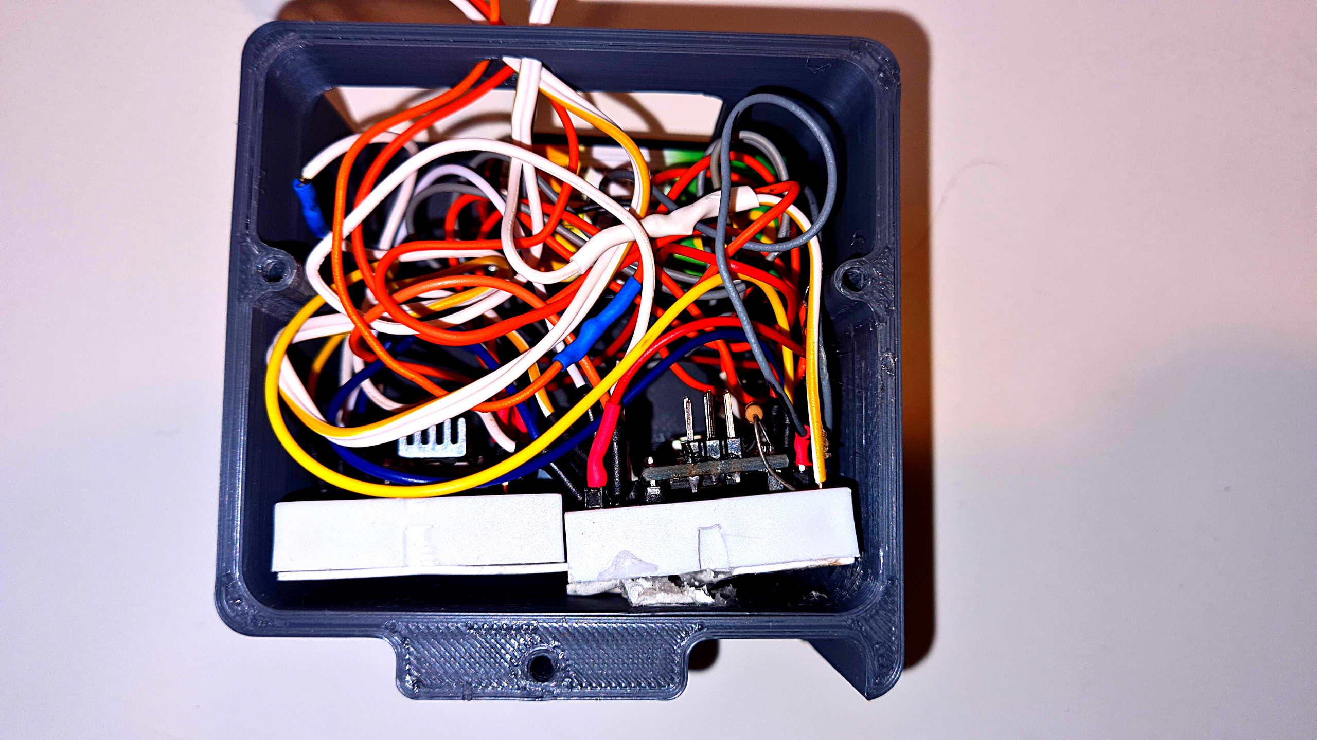
Electronics Case Assembly
.png)
Put your circuit in the electronics case. Run the cables of the stepper, the End-Stop switch and the IR Obstacle Sensor through the hole.
IR Obstacle Sensor Holder Assembly
.png)
.png)
Screw the IR Obstacle Sensor to the hole and use a nut to tighten it.
Final Assembly Part 1
.png)
.png)
.png)
.png)
- Insert the bearing.
- Add the T8 screw through the bearing and through the Presser's T8 nut. (The T8 screw needs to be 70mm to 82mm long. If you have a longer screw you should cut it to the wanted size using a tool like a hacksaw. Otherwise you can try 3D printing one.)
- Then add the 3D printed rod.
Final Assembly Part 2
.png)
.png)
.png)
.png)
- Tighten the coupler to the motor's shaft.
- Then tighten it to the T8 screw.
- Lastly screw the motor to the base with two screws.
Final Assembly Part 3
.png)
.png)
.png)
Add the end-stop switch as shown in the picture and screw the Cover to the Base with 5 screws.
Final Assembly Part 4
.png)
.png)
.png)
.png)
Screw the IR Obstacle Sensor Holder to the front of the base with 2 screws. Finally, screw the Electronics Case to the Cover with 3 screws!
Enjoy Your Creation!

Well done! This project is now completed! Now tie it to a Hand Sanitizer/Soap Dispenser turn on the switch and you now have your own safe way of Automatic Hand Sanitation during these difficult times!
Thanks for reading! If you enjoyed make sure to check out my YouTube channel for upcoming projects!