Automatic Fan/Air Conditioning System
by InnovativeEngineer in Circuits > Arduino
527 Views, 3 Favorites, 0 Comments
Automatic Fan/Air Conditioning System
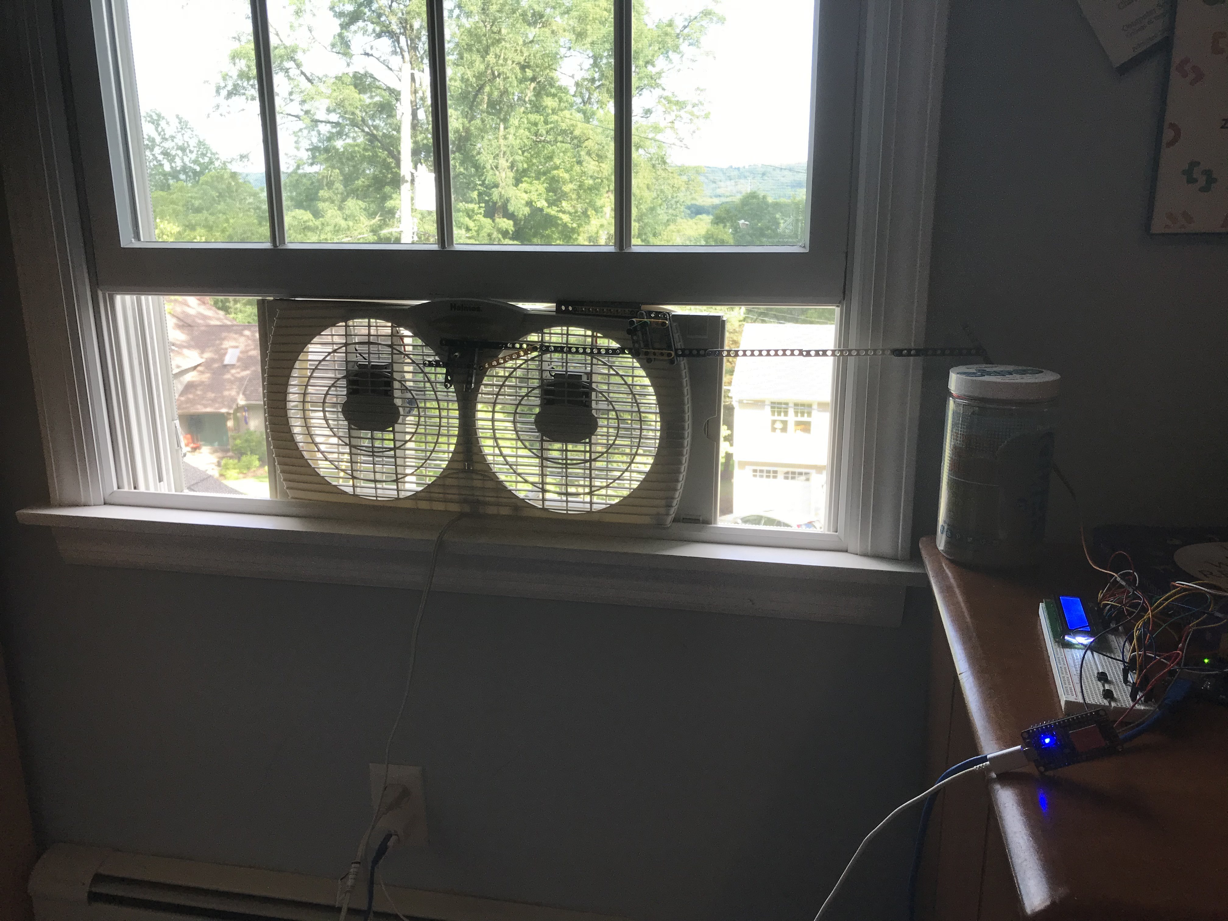
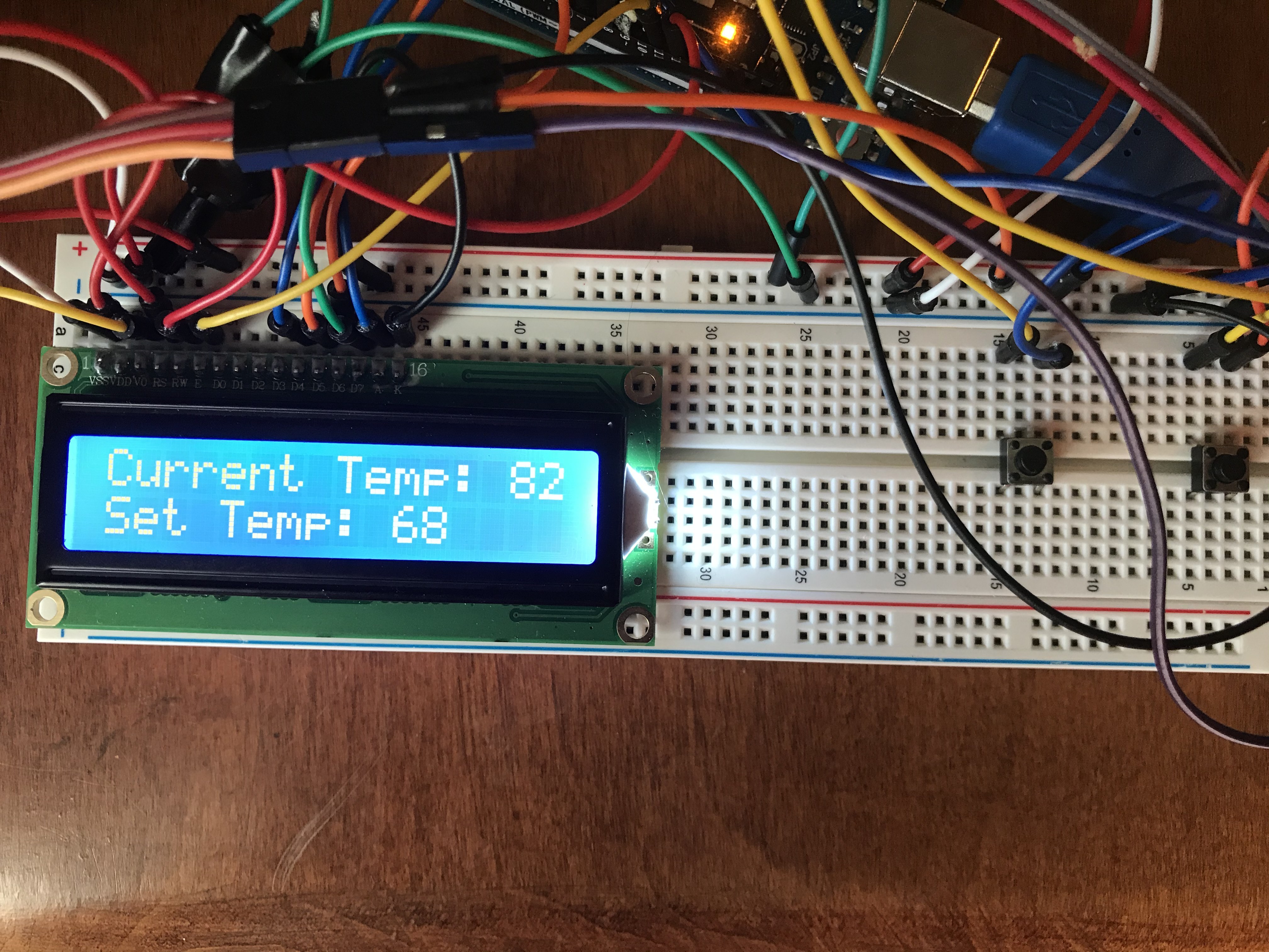
Welcome! In this Instructable I will walk you through how to build your very own automatic Fan/Air Conditioning System. This Instructable deals with a window fan, which is used to cool down rooms in the heat of summer. The goal of this project is to create a system that will automatically monitor and regulate the temperature of a room by controlling a common window fan. Additionally, the ability to control the fan wirelessly with a smartphone will be implemented using a Esp8266/NodeMCU Wifi Development board along with the IoT app, Blynk. The main control system utilizes an Arduino and a few other components. Let's get into it!
Gathering Components
For this Instructable, you will need:
- Arduino Uno (comes with USB data cable) - Buy Here (Amazon) (other similar boards like the Arduino Mega will work as well)
- 16x2 LCD Display (in this project, I use a display without a 16 pin module adapter. If you have the adapter, Arduino has tutorials on how to wire the module adapter up to an Arduino Uno)
- DHT11 Temperature/Humidity Sensor (3 pin) - Buy Here (Amazon) - there are two versions: a 3 pin and a 4 pin. Here I use the 3 pin sensor as it is easier to use and wire up because you don't have to add a resistor. Make sure to check the pinout of your sensor, as different manufacturers have slightly different pinouts for this sensor.
- 10k Ohm Potentiometer - Buy Here (Amazon)
- 2 Pushbuttons - Buy Here (Amazon)
- Metal Gear Servo - Buy Here (Amazon) - you do not have to use a metal gear servo, as it all depends on your window fan. The servo will be used to move the switch on the fan, so it all depends on how much force is required to move the switch. I use a beefy metal gear servo because my fan has a sturdy switch, and in general, metal gear servos are way less likely to break than regular plastic gear servos.
- Male to Male & Male to Female Jumper Wires - Buy Here (Amazon)
- Esp8266/NodeMCU Wifi Development Board - Buy Here (Amazon)
- Blynk (Free mobile app available on App Store and Google Play)
- Micro USB Cable for programming Esp8266/NodeMCU
- Miscellaneous materials for constructing a device to allow the servo to move the switch on the fan. (A picture of my device will be included further down)
Wiring It All Up
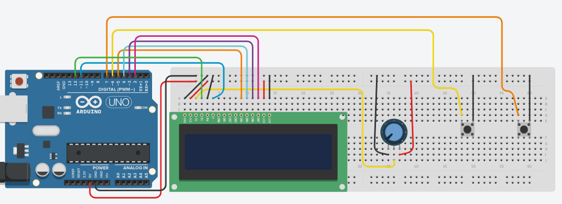
The custom-made wiring diagram for the Arduino is shown above.
*IMPORTANT NOTE*
The DHT11 and Esp8266/NodeMCU both still have to be wired up to the Arduino. The servo also needs to be wired up to the Esp8266/NodeMCU.
Connections:
DHT11 ---> Arduino
VCC ---> 5v (on breadboard)
GND ---> GND (on breadboard)
Signal (S) ---> Analog Pin A0
____________________________
Arduino ---> Esp8266/NodeMCU
Digital Pin 8 ---> Digital Pin 3 (D3)
Digital Pin 9 ---> Digital Pin 2 (D2)
____________________________
Servo Connections
Red Wire ---> 5v (on breadboard)
Black/Brown Wire ---> GND (on breadboard)
Yellow/Orange Wire ---> Digital Pin 0 (D0) on Esp8266/NodeMCU
Programming the Arduino
The downloadable Arduino file for the main Arduino circuit is located below.
*IMPORTANT*
Make sure you have the required libraries installed (dht11 and LiquidCrystal)
*If you already have both of these libraries installed (double check, as there are many different DHT11 libraries) then you can upload the Arduino code from the file above to your Arduino*
To download the LiquidCrystal Library, in the Arduino IDE, click on Sketch, Include Library, and then click on Manage Libraries. Wait for all of the libraries to load, and then type LiquidCrystal in the search bar. It should be the first library to show up, by Arduino and Adafruit. (FYI this may already be installed, as this is one of the libraries that often comes built-in when you download the IDE. If it is, then just go to the next paragraph) Make sure it is the most recent version, and click Install. When it is done installing, close out of the IDE.
To download the dht11 library, go here, and click on the green button on the right that says "Clone or Download", and click "Download ZIP". A zip file should be downloaded to your device. Open back up Arduino IDE and click on Sketch, Include Library, and Add .ZIP Library. Select the compressed ZIP file you just downloaded. Once the library has successfully been installed, close out of the IDE once more. Re-open it and navigate to the Custom_Fan_AC_System. Now you can select your board and port and upload it to the Arduino.
Downloads
Setting Up Blynk With the Esp8266/NodeMCU
First off, download the Blynk app from either the App Store (iOS) or the Google Play Store (Android).
Open up the app, and make an account. Create a New Project, and name it Automatic Fan A/C System. Choose Esp8266 or NodeMCU for the device (either should work). Choose Wifi as the connection type. Then click "Create Project". An authentication code should be created. That will be used later.
Now click on the screen (or swipe left) and a menu should pop up. Click on Styled Button, and enter System Control as the name. For Pin, scroll to Digital and select D1. Slide the Mode from the Push to the Switch. For the off label, name it Room. For the on label, name it Mobile. Then click OK at the top right of the screen. Click on the screen again to go to the menu, and click slider. Name it Fan Switch. For the Pin, scroll to Virtual and select V0. If the set range is from 0-1023, change the 1023 to 180. Then click OK at the top right. Click on the screen one last time and scroll down until you see Segmented Switch. Click "Add Option" and since my fan has three settings, Off, Low, and High, I named the first option Off, then Low, then High. DO NOT CONNECT THIS SWITCH TO A PIN. Place this switch below the slider. (the reason for this switch will become clear later)
_____
There is one more library (possibly two) you need to install, and that is the Blynk library. Again, go into the Arduino IDE, to Sketch, Include Library, then Library Manager. Search Blynk in the search box, and the one by Volodymyr Shymanskyy should come up. Download the latest version and once it is done, close out of the IDE.
_____
Make sure you have the Servo library installed. It is a built-in library for the IDE, so it should be installed. The library is by Michael Margolis and Arduino. If it is not installed, install the latest version and exit out of the IDE.
_____
The Esp8266 needs to be setup within the IDE. It is rather simple, just open the IDE and go to File, Preferences, and in the Additional Boards Manager URLs box, type in:
http://arduino.esp8266.com/stable/package_esp8266c...
Then click OK.
_____
Go to Tools, Board, then Boards Manager. Search for Esp8266. If it is not installed, install it and exit out of the IDE once more.
_____
Open up the IDE, and plug your Esp8266/NodeMCU into your device with the Micro USB Cable. Make sure the Arduino Uno is unplugged. Go to Tools and select the available port, and for the Board, choose NodeMCU 1.0 (Esp-12E Module).
_____
Download the file for the Esp8266/NodeMCU above, and read through my comments and fill in the necessary information. Once that is done, upload it to the board.
Constructing the Servo/Fan Switch Device
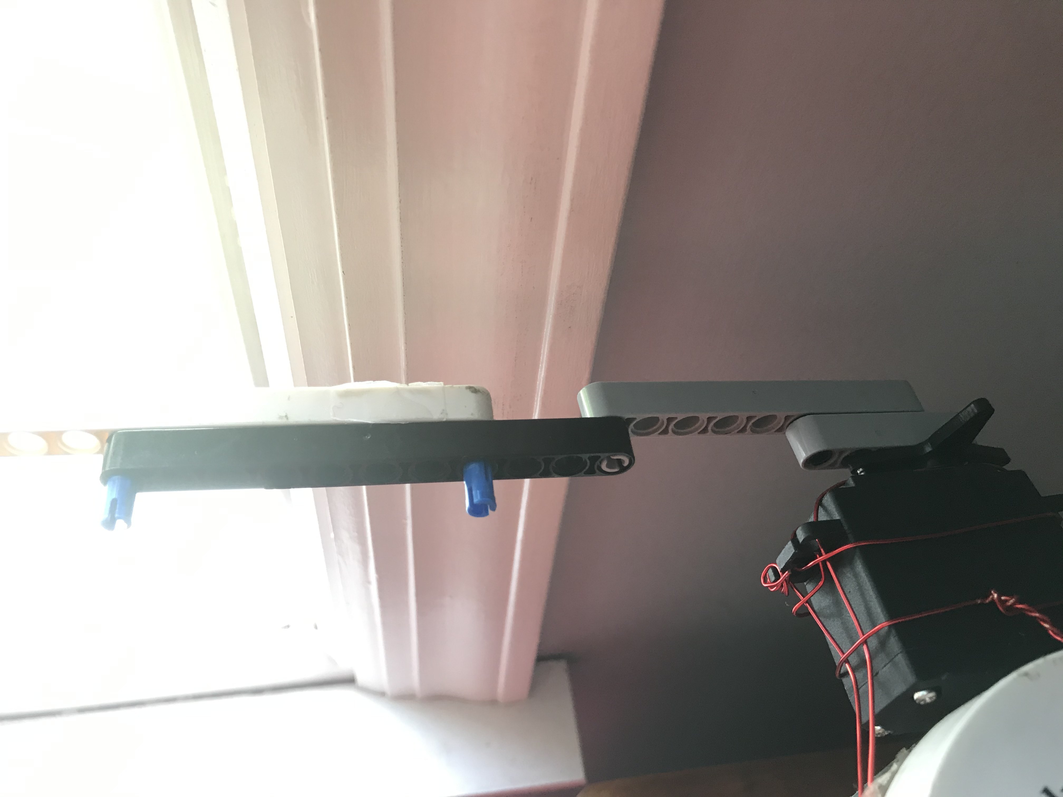

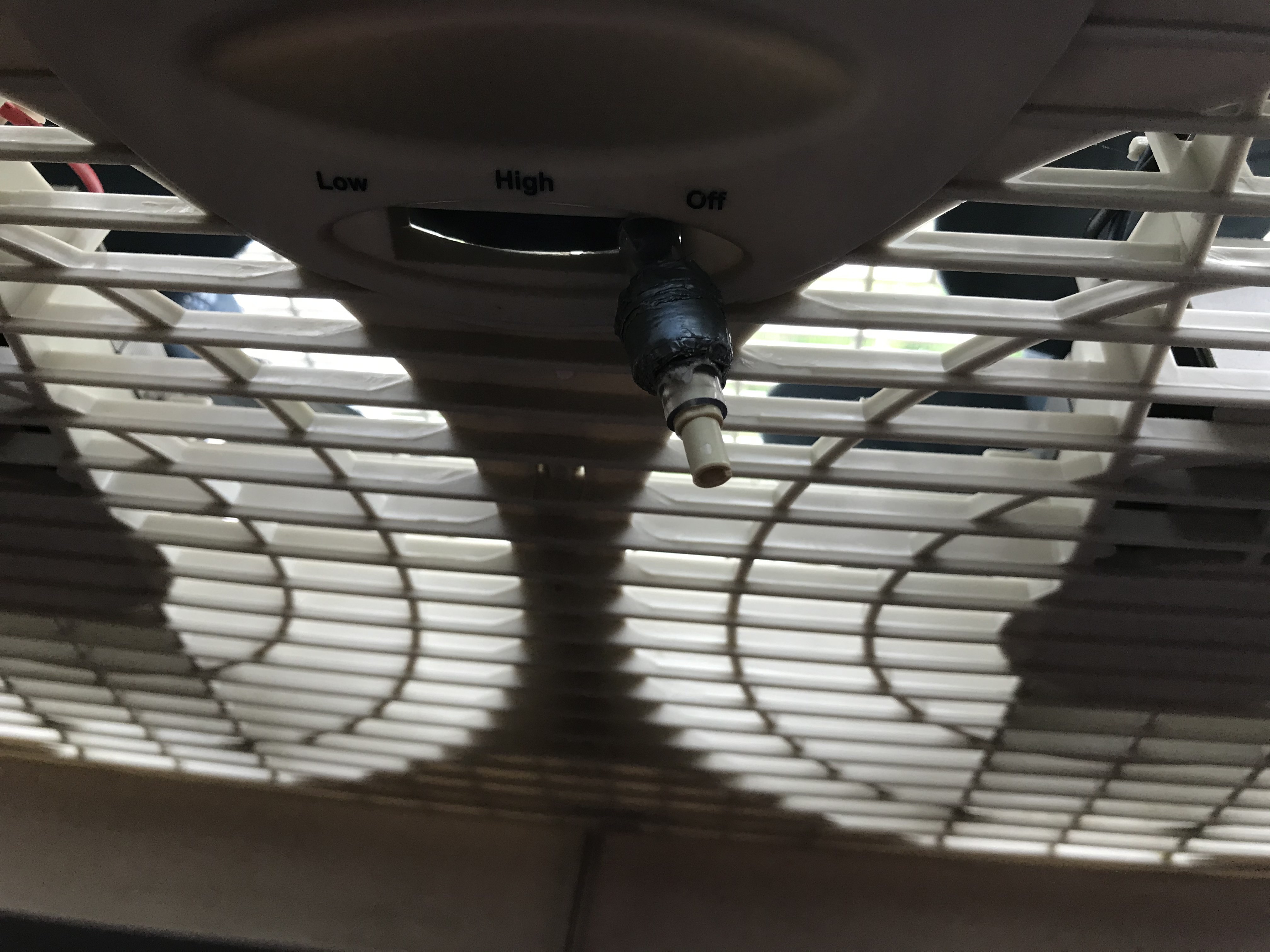
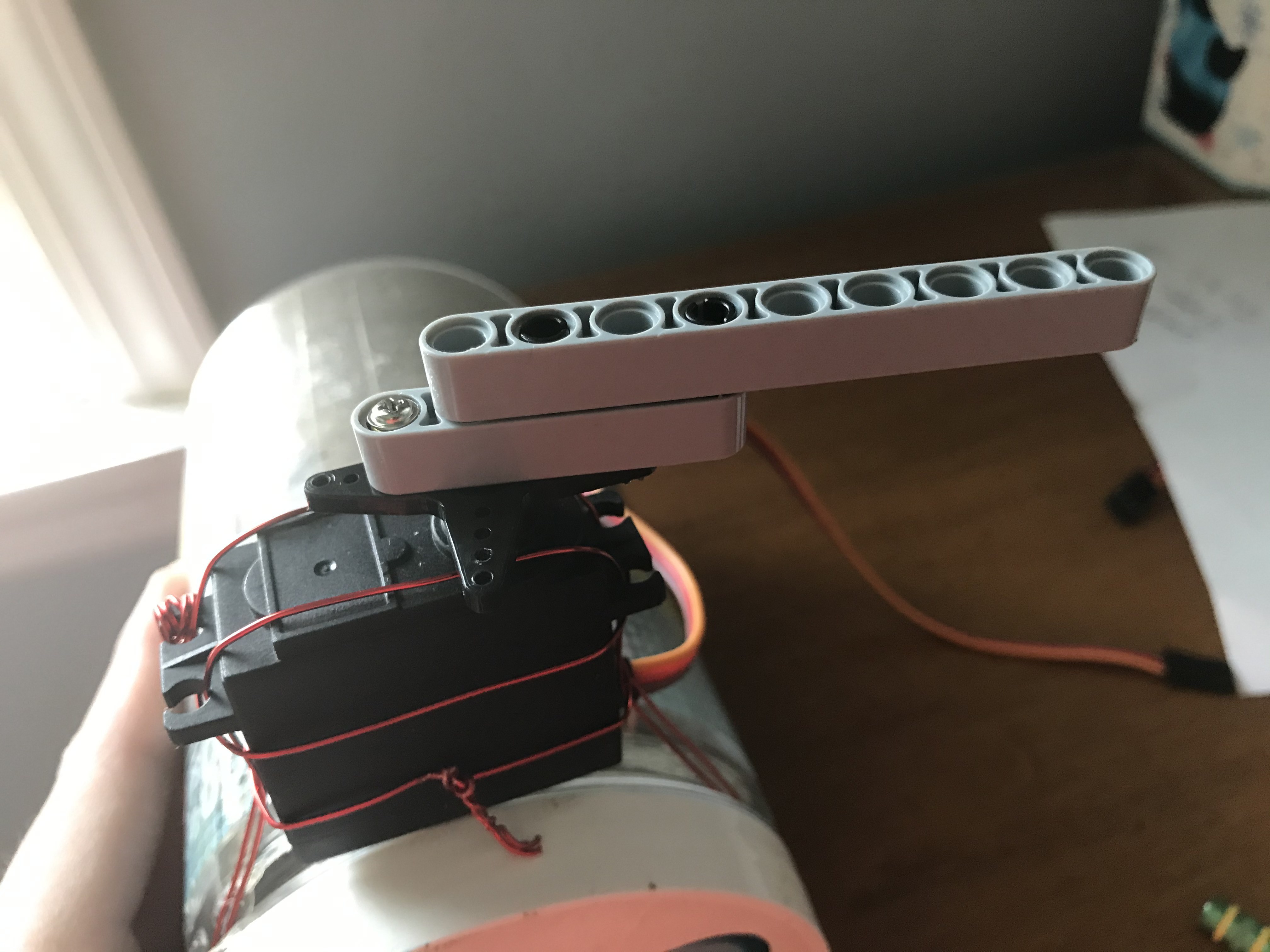
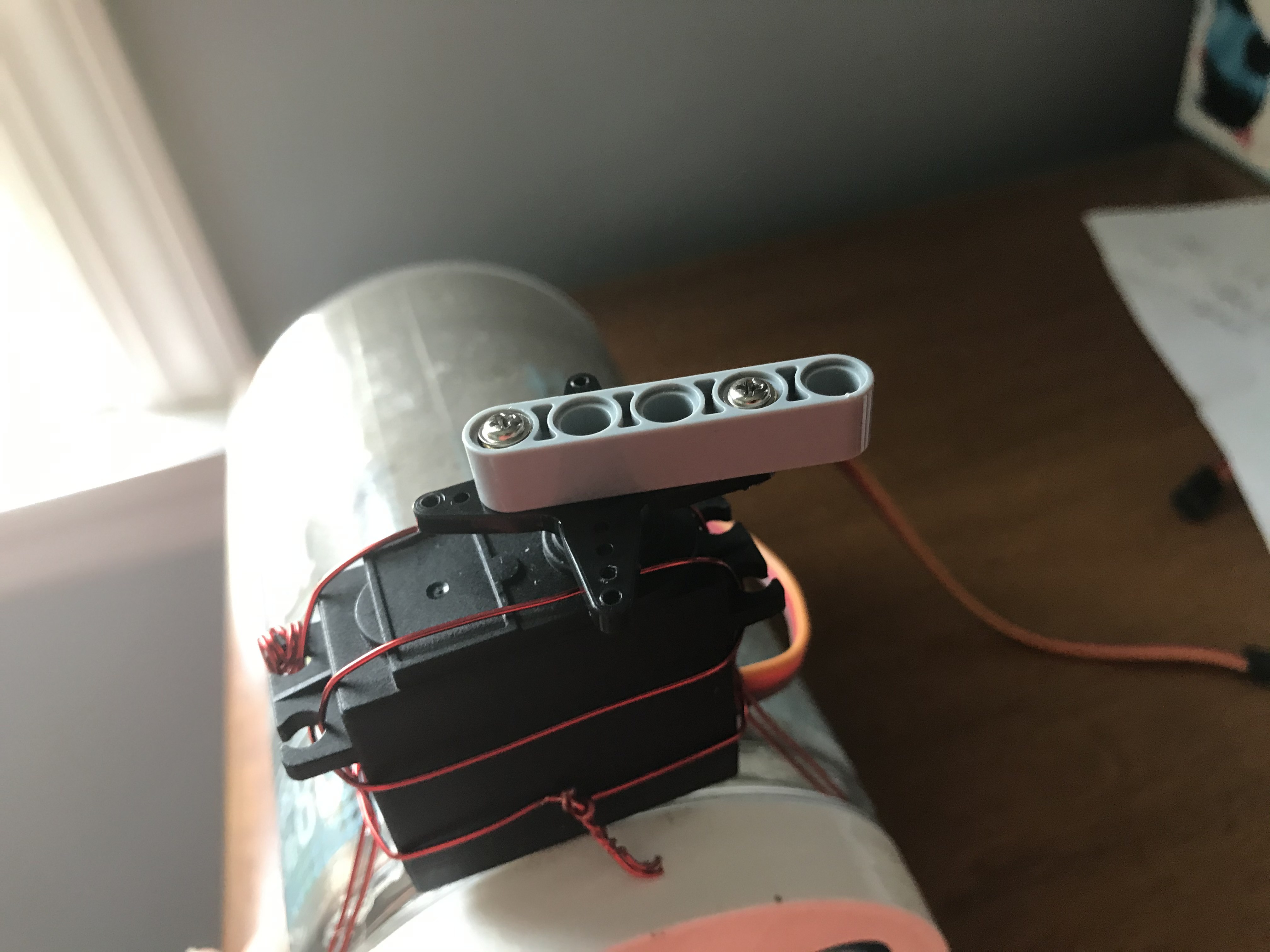
Here I will show you how I constructed a device to allow the servo to switch the fan between Low, High, and Off.
I used a piece of clear tubing that fit snugly around the switch of my fan, and I used Lego Technic pieces to create an arm with a sliding holding mechanism that would mount under the window, just like the fan. This all depends on your fan and the setup of the room. I have a desk near the fan, so I can just mount it to something on the desk. If you do not have a solid stationary object near the window, you may need to attach the servo to the fan directly.
The Lego arm can move freely for a certain distance, a distance that allows for the switch to move fully from end to end. I also mounted a Lego piece to the servo horn by using some small screws and brass adapters that came with the servos. I did not strongly secure the Lego arm around the tube that is on the switch because the switch needs to move freely enough because the angle of the tube changes due to the switch being a semicircle. I just made a Lego box around the switch so the arm would not have trouble turning the fan on and off. There is a video below that you can download and watch that shows the arm up close and how it moves the switch. On to testing!
Testing & Overall Explanation of Project
I decided to make this project after my brother and I repeatedly disagreed on the temperature of our room. I like the fan on a lot so the room is very cool, and he ends up turning off the fan a lot of the time, saying that it is too cold. Additionally, when it is hot out, I sometimes forget to turn the fan on when I'm not in the room, and when I go up to sleep the room is so hot, and I have to turn on the fan then, which doesn't change the temperature fast enough for a good sleep. So I set out to make a system that can solve the problem.
_____
This system has two elements: the Automatic Part and the Manual Part
The Automatic Part is controlled by the Arduino, where it constantly takes the temperature and displays it on the LCD screen. The Arduino also uses the two pushbuttons to adjust the desired temperature of the room. In Automatic Mode, or Room Mode, the Arduino turns on the fan when the desired temperature is lower than the actual temperature. When the desired temperature is reached, it turns off the fan. The Blynk App is used to control the whole system, as the button can turn the fan into Room Mode and into Mobile Mode, which allows for the user to control the servo and the fan remotely. When in Mobile Mode, the user uses the slider to control the servo. The Arduino still keeps displaying the Current Temperature and the Desired Temperature on the LCD.
_____
Testing:
Once you have uploaded the code onto both the Arduino and the Esp8266/NodeMCU and created a way for the servo to control the fan switch, you have to turn everything on. Power up the Arduino and Esp8266/NodeMCU (whether that be through USB, a 5v source, etc.) and wait a few seconds until everything is turned on. Then open the Blynk app and enter the project screen and hit the play button at the top right. It should be connected to the Esp8266/NodeMCU. Click the pushbuttons to make sure they adjust the desired temperature, and make sure the LCD also changes with it. In the Blynk app, click the switch so the system is in Mobile Mode. Then move the slider and release it and you should see the servo move (to the position of the number of degrees that the slider shows. If it doesn't show the value, go into the slider and check the switch that says "Show Value"). Move the slider around until you get the exact numbers that move the servo so your fan turns on and off. Enter these numbers into the Arduino code. * I only programmed in the low and off settings, even though mine has a high setting, as the low setting is powerful enough * Re-upload the code to the Arduino.
The purpose of the segmented switch underneath the slider is to display the values for the settings on the fan, since you will be controlling remotely with the slider. I changed the name of my options to
Option 1. Off - (value)
Option 2. Low - (value)
Option 3. High - (value)
This way I know where to put the slider when I am controlling the fan remotely. You should enter your servo values into the options so you know where to move the slider. Then you can switch the System back into Room (Automatic) Mode.
____
Once that is done. just set the desired temperature of the room with the two pushbuttons, and the Arduino system will do the work!
//
If you have any questions/problems, feel free to drop them down below and I'll be happy to help you out! :)