Automatic Door Security System
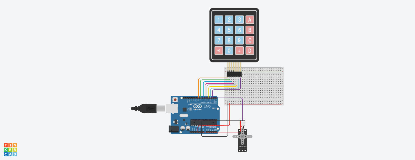
In this instructable, we'll guide you through the process of creating an Automatic Door Security System using an Arduino. This system combines the power of electronics and programming to enhance the security of your space. By integrating a keypad and a servo motor, you'll be able to control access to a door with a personalized password, adding an extra layer of protection to your environment.
Imagine having the ability to secure a room, storage area, or any space you want with a simple yet effective security mechanism. This project is perfect for anyone interested in learning about Arduino programming, electronic components, and practical applications of technology.
Whether you want to add a touch of tech-savvy flair to your home or explore the world of DIY electronics, this project offers a great opportunity to dive into the exciting realm of automation and security. Join us as we guide you through the step-by-step process of building your very own Automatic Door Security System.
Supplies
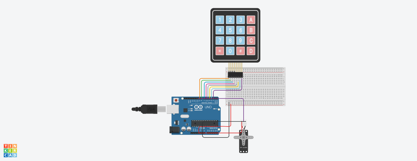
Tools and Materials Used:
1. Arduino Board: You'll need an Arduino board (such as Arduino Uno) to act as the brain of the system. You can find Arduino boards at Arduino Store.
2. Servo Motor: A servo motor is used to physically control the door's locking mechanism. You can find servo motors at electronics stores or online retailers like Adafruit or SparkFun.
3. 4x4 Keypad: The keypad allows users to input the password. You can find these keypads at electronics stores or on sites like Amazon.
4. Jumper Wires: Jumper wires are essential for connecting components on the breadboard. You can find them at electronics stores or online retailers.
5. Breadboard: A breadboard provides a platform for prototyping and connecting components without soldering. Available at electronics stores and online retailers.
6. USB Cable: Required to connect the Arduino board to your computer for programming and power.
7. Computer: You'll need a computer to write and upload the Arduino code.
8. Arduino IDE: The Arduino Integrated Development Environment (IDE) is necessary to write, compile, and upload the code to the Arduino board. Download it from the Arduino website.
9. Screwdriver: Depending on the servo motor, you might need a screwdriver for assembling components.
10. Door or Hatch: The physical object you want to secure using the system.
11. Screws and Mounting Hardware: Required for attaching the servo motor to the door or hatch.
12. Power Source: Depending on your setup, you might need an external power source for the servo motor if the Arduino cannot provide sufficient power.
13. Optional Enclosure: A protective enclosure for the electronics can enhance the project's aesthetics and safety.
**Printed Circuit Board (PCB) (Optional): Instead of using a breadboard, you can design and fabricate a custom PCB for a more permanent setup.
Make sure to follow safety precautions while working with electronics, and double-check the specifications and compatibility of components before purchasing.
Links to sources for purchasing components:
I HAVE MADE THIS PROJECT ON TINKERCAD, AND I HAVE TAKEN THESE COMPONENTS ONLY:
- Arduino
- Servo Motor
- Breadboard
- Jumper Wires
- 4*4 Keypad
Downloads
Add Components to the Workspace
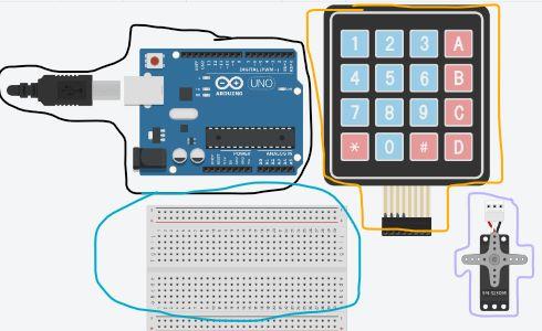
- From the components panel on the right, search and add the following components to the workspace:
- Arduino Uno
- Servo Motor
- 4x4 Keypad
- Breadboard(Small Size Suggested for this project)
- Drag and arrange the components on the workspace to create a layout similar to the physical setup.
Wiring the Circuit
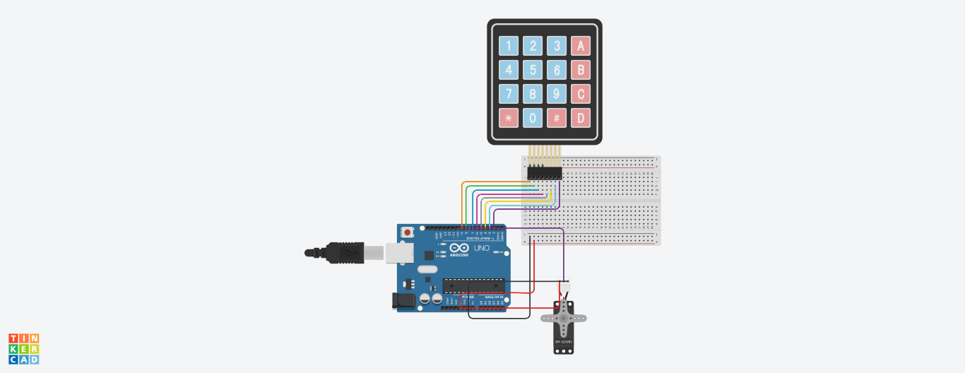
Connect the components using virtual jumper wires:
- Connect the power (+5V) and ground (GND) pins of the keypad to the +5V and GND pins on the Arduino.
- Connect the keypad's row pins (R1, R2, R3, R4) to Arduino pins 9, 8, 7, and 6 respectively.
- Connect the keypad's column pins (C1, C2, C3, C4) to Arduino pins 5, 4, 3, and 2 respectively.
- Connect the servo motor's signal (control) pin to Arduino pin 10.
- Connect the servo motor's power (+) and ground (-) pins to +5V and GND on the Arduino respectively.
Programming the Arduino
- Click on the Arduino component to open the code editor.
- Delete the existing code and replace it with this code:
Downloads
Reviewing the Logic of the Code
Review the code to understand its functionality:
- The code initializes the servo and keypad in the setup() function.
- In the loop() function, it checks for keypresses on the keypad.
- If a key is pressed, it adds it to the password array and compares it to the correct password.
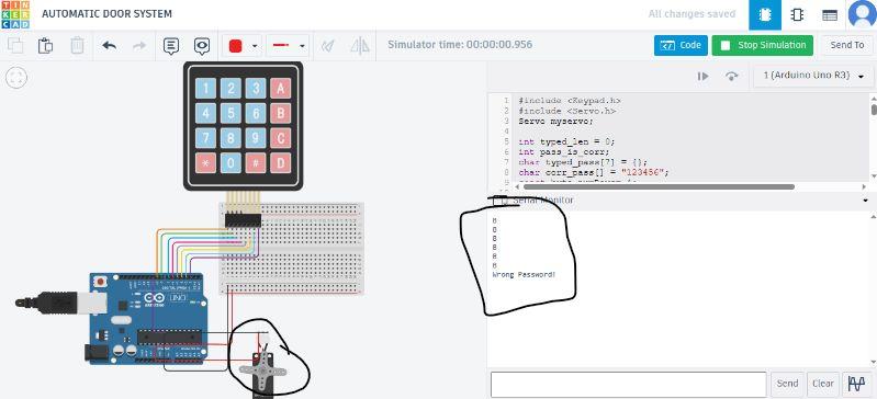
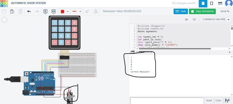
- If the user typed 6 times, and then if password matches, the servo rotates to unlock the door temporarily, and serial monitor print "Correct Password", else servo not rotates and Serial monitor print "Wrong password".
Simulation and Testing Password Input
- Close the Arduino code editor and return to the main Tinkercad workspace.
- Arrange the components as you want them to be for simulation.
- Click the "Start Simulation" button to run the simulation.
- In the simulation, click on the virtual keypad's buttons to input a password (e.g., 123456).
- Observe the behavior of the servo motor and the messages printed in the serial monitor.