Automatic Card Distributor
by Tom Maenhoudt in Circuits > Raspberry Pi
543 Views, 1 Favorites, 0 Comments
Automatic Card Distributor
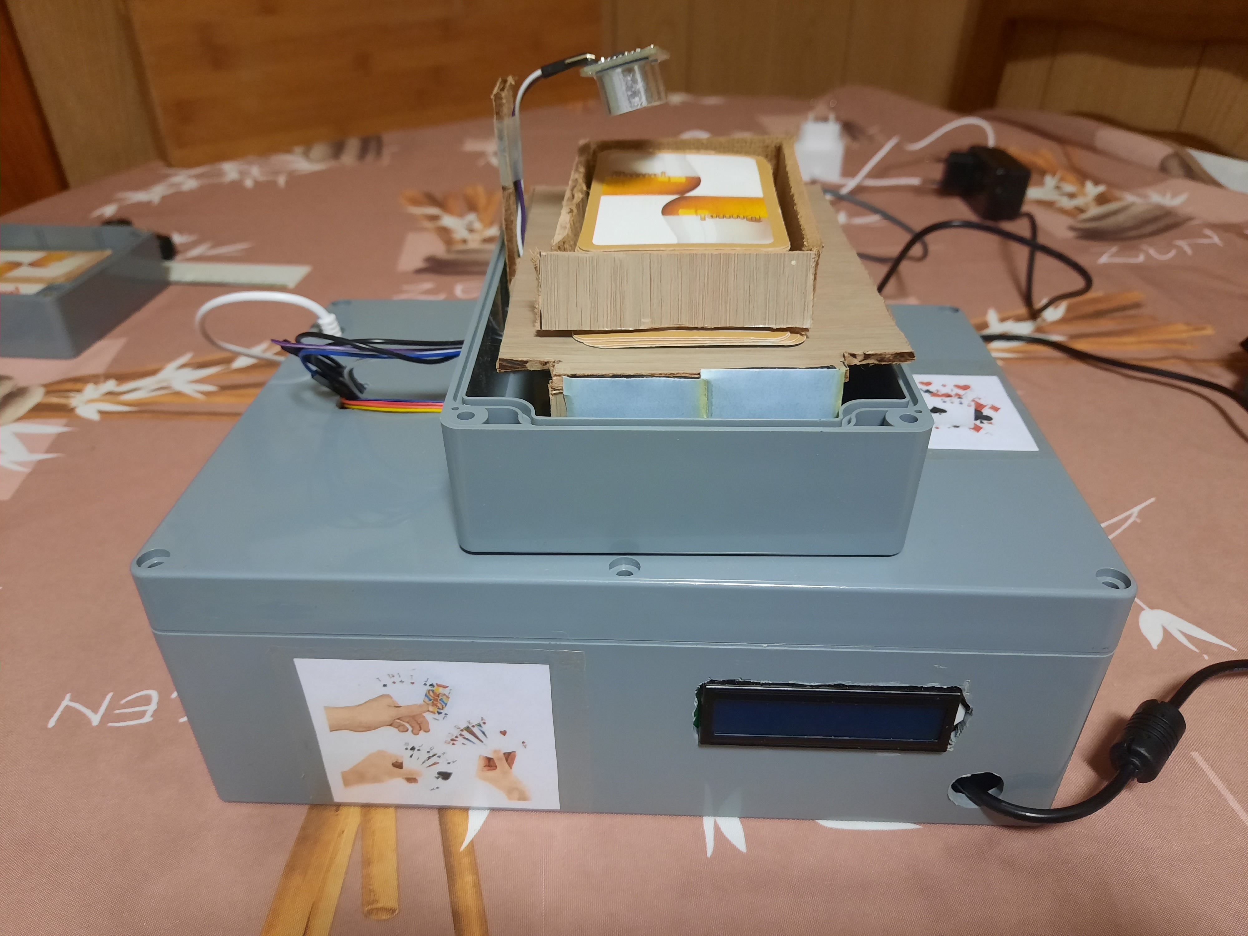
I have chosen a smart card distributor as my first project because I like to play a cardgame. The thing I dislike the most is dealing cards. You have to remember for every game how many cards every person gets. That gets confusing when you know a lot of card games. My project will also help people that have trouble with distributing cards like older people and people who are suffering from Parkinson.
Downloads
Supplies
- 1 Raspberry Pi (I used a Raspberry Pi 4)
- SD card (16GB recommended)
- 1 Outbread piece for Raspberry Pi (T-piece)
- 2 breadboards
- 1 Power supply module for breadboard, 5V and 3V3
- 1 LCD display
- 1 Potentiometer
- 1 MPU6050 (accelerometer and gyroscope)
- 1 NPN transistors
- 1 PCF8574N I/O expander
- 1 stepper motor
- 1 ULN2003 breakout board to control stepper motor
- 1 HC-SR04 ultrasonic sensor
- 1 5V DC motors
- 1 diodes
- 6 470 Ohm resistors
- 4 10K Ohm resistors
- Electric wire to connect everything
Usefull to have while making:
- Soldering iron
- Solder
- Dremel or jig saw (something to cut wood and abs plastic)
Software:
- Putty
- MySQL workbench
- Win32 Disk Imager
- Code editor (I recommend Visual Studio Code)
- WinSCP
- Raspbian image
Preparing the Rasperry Pi
First we need to prepare the Raspberry Pi before we do anything else. Because everything will be running of the Pi so this is one of the most important pieces of the card distributor.
Installation:
Download the Raspbian image from https://www.raspberrypi.org/downloads/raspberry-pi-os/
- Download the ZIP-file
- Extract the ZIP-file where you can find it easily
- Open Win32 Disk Imager and select the extracted image
- Select the SD card in the dropdown menu and click write
- Once the write process is done you can close Win32 Disk Imager
Now we need to do a few more things before we can connect to the Pi
- Navigate to the boot folder on the SD card
- Open the file cmdline.txt
- Add 'ip=169.254.10.1' at the end of the line separated with a space
- Save and exit the file
- Create in the same directory a file called ssh and remove the extension (this wil enable ssh on the first boot so we can connect to the Pi)
- Safely eject the SD card and put it in the Pi
Now we can connect to the Pi:
- Grab an ethernet cable and insert one end in the Pi and the other end in your computer
- Open Putty
- Enter 169.254.10.1 in the Host name field
- Make sure SSH is selected and the port is 22
- Click open
- If you get a warning you can just continue and ignore it
- The username is pi and the password is raspberry
Configuration and installation of software:
Open raspi-config with the following command:
sudo raspi-config
Select the 5th option: Interfacing options
Enable SPI and I2C
Disable the following things in the 3th option: Boot options:
- Splash screen
- Choose cli for startup and not desktop
Wifi setup:
Wifi is usefull to easily navigate to the website. Make sure you have your wifi credentials close.
To setup wifi we need a few things:
Add your wifi by using this command and change SSID and PASSWORD to your information:
sudo wpa_passphrase "SSID" "PASSWORD" >> /etc/wpa_supplicant/wpa_supplicant.conf
Execute this command to reconfigure your wifi:
sudo wpa_cli
Select the correct interface:
interface wlan0
Reconfigure the interface:
reconfigure
Check if the reconfiguration was succesfull with this command:
ip a
If you see an IP-address on the wlan0 interface then everything is setup.
Updating operating system
Update the operating system with these 2 commands:
sudo apt update
sudo apt full-upgrade
Seting up MariaDB:
Installing Apache Webserver:
sudo apt install apache2 -y
lnstalling MariaDB server:
sudo apt install mariadb-server -y
Now we need to reboot:
sudo reboot
It's recommended to secure the MariaDB installation. You can do it by running this command:
sudo mysql_secure_installation
First you'll be asked for the current root password but the default installation doesn't have one so press enter.
Next you'll be asked if you want to set a root password, type y. Make sure you can remember the password!
- Enter y to remove anonymous users
- Enter y to disable root login remotely
- Enter y to remove test databases and access to it
- Enter y to reload priveleges
Your MariaDB installation should be secure!
Now we can create a new user:
Enter the mysql shell with this command:
sudo mysql
Create a user with the username mysql and a password (your_password) the following commands:
create user mysql@localhost identified by 'your_password';
grant all priveleges on *.* to mysql@localhost;
FLUSH PRIVILEGES;
Exit the mysql shell with this command:
exit;
Python packages:
Python should already be installed unless you chose the Lite version:
sudo apt install python3-pip
We need a good amount of Python packages, you can install all of them with the following command:
pip3 install mysql-connector-python flask-socketio flask-cors gevent gevent-websocket
Now we need to reboot once more
sudo reboot
Setting Up Visual Studio Code and MySQL Workbench
Connecting to the Pi with MySQL Workbench:
Open MySQL Workbench
Make a new connection to the Pi with the following information:
- Connection name: Raspi
- Connection Method: Standard TCP/IP over SSH
- SSH Hostname: IP-address of the Pi
You can get the IP-address with this command:
ip a
- SSH Username: pi
- MySQL Hostname: 127.0.0.1
- MySQL server Port: 3306
- Username: mysql
Click ok and enter the password for the user pi and then enter the password for the user mysql.
Setting up Visual Studio Code:
Open Visual Studio Code
Install these 2 extensions:
- Remote - SSH
- Remote - SSH: Editing Configuration Files
Press in Visual Studio Code F1 and type in ssh
Choose Remote SSH: Add new SSH host
Fill in ssh pi@IP-address
In the next step press enter
The connection is now made to the Pi. You can connect to the Pi by pressing F1 and selecting connect to Remote host.
Enter the password so Visual Studio Code has access to the Pi.
One more thing: Install the Python extension on the remote machine so you can easily run and debug code.
Fritzing Diagram
![20200612_133037_-_Copy[1].jpg](/proxy/?url=https://content.instructables.com/FRC/QUCB/KBB439K4/FRCQUCBKBB439K4.jpg&filename=20200612_133037_-_Copy[1].jpg)
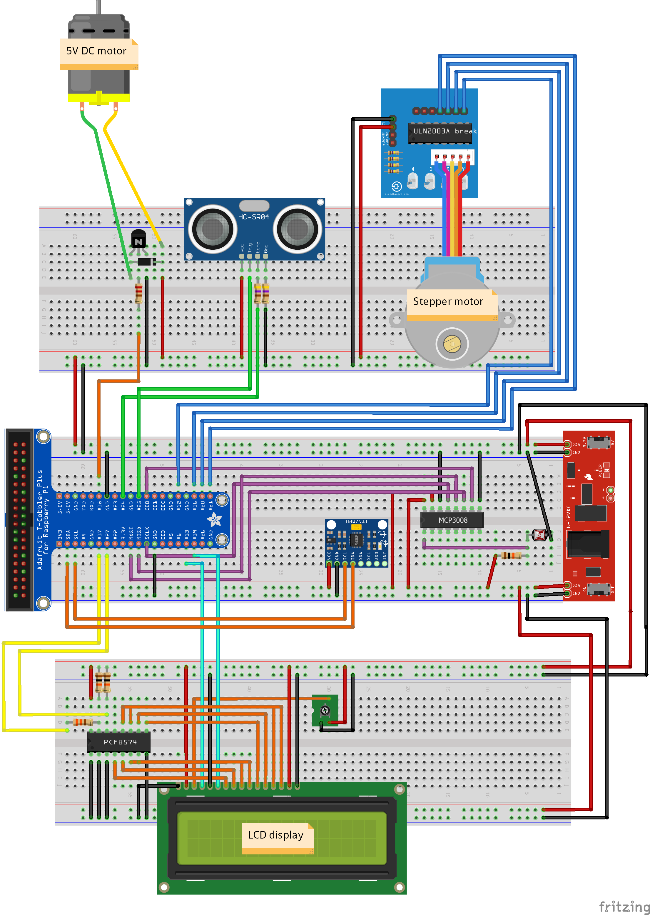
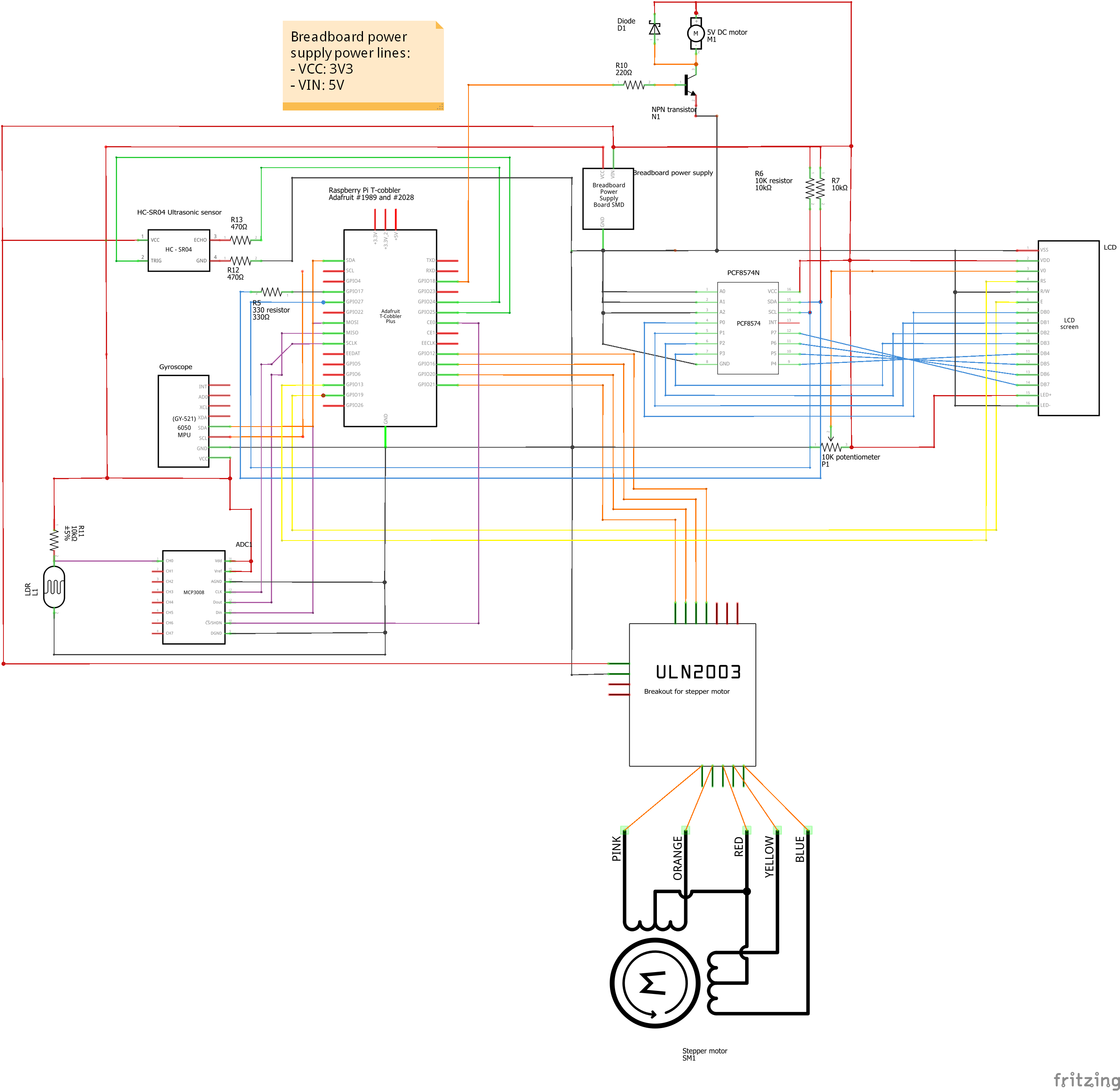
In this step I will explain the circuit.
The schematics above are made with Fritzing.
DC motor:
Connect GPIO 18 to the base of the collector, the middle pin on a npn transistor. Connect the ground of the motor to the collector from the transistor and the power of the motor to 5V. Connect the ground of the transistor to the ground line. Connect the diode in barrier over the motor so it blocks the currunt from flowing directly to the transistor.
Stepper motor:
Connect the stepper motor to the control board. On the control board there are on one side pins to connect 5V and ground. The other pins are control pins. These pins control the magnets inside the motor so it can turn. Connect these pins to GPIO 12, 16, 20 and 21 on the Raspberry Pi.
HC-SR04 Ultrasonic:
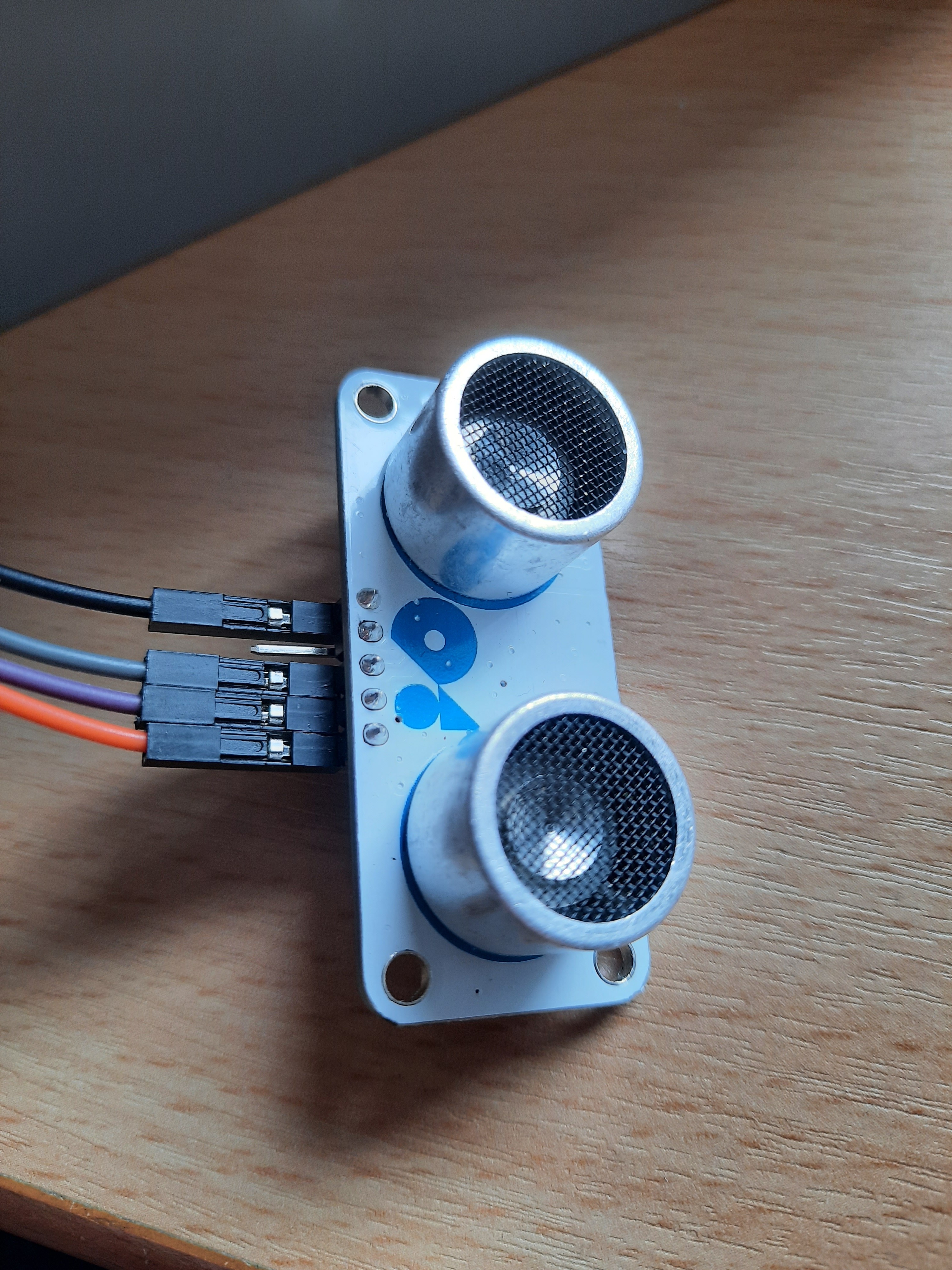
This sensor can measure distances to about 4.5 meters using sound.
Connect the VCC pin to the 5V, the trigger pin to GPIO 25, the echo pin with a resistor of 470 Ohm to GPIO 24 and the ground with a resistor of 470 Ohm to the ground.
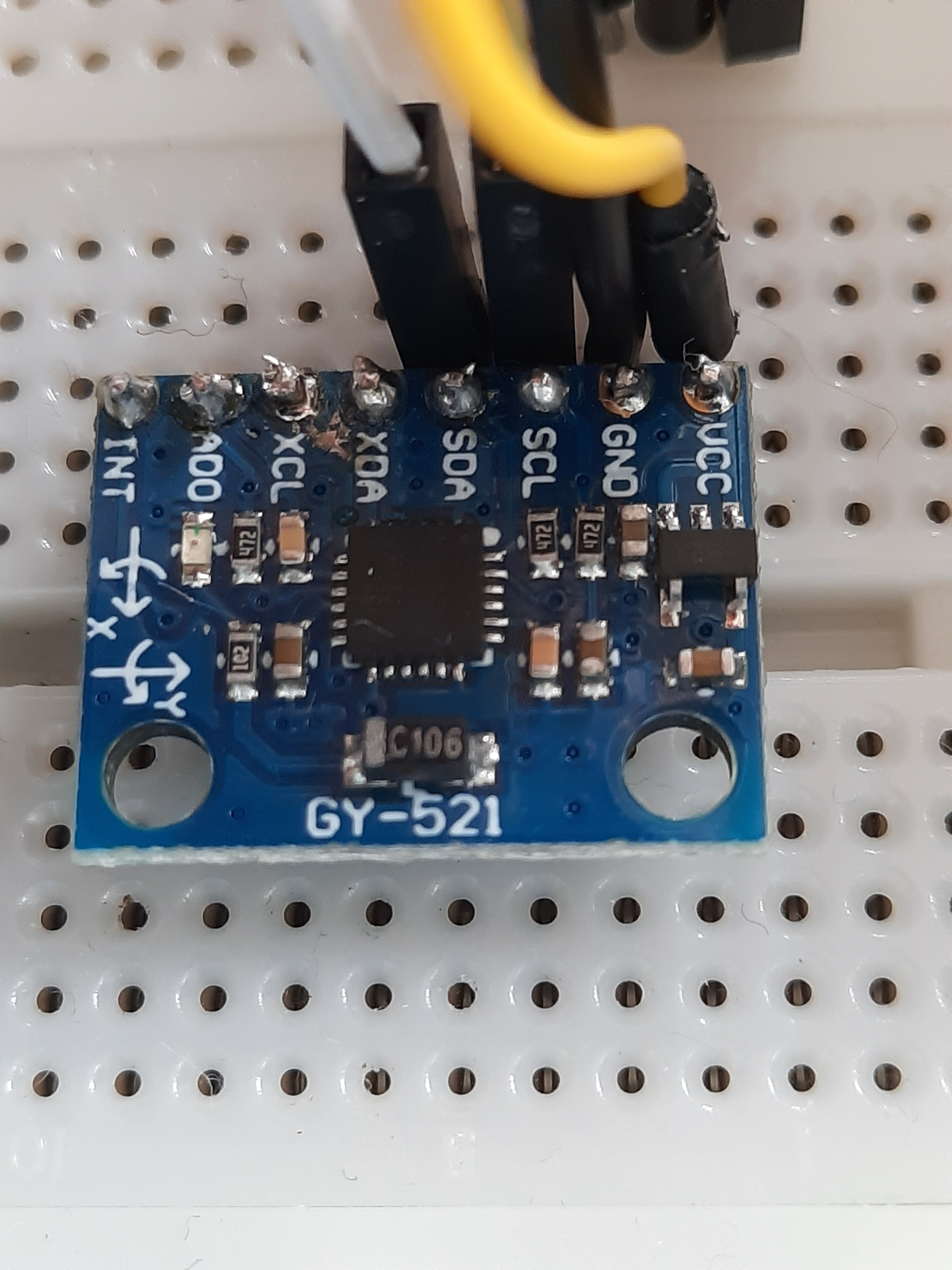
MPU6050:
Connect the VCC pin to 3V3, the ground to ground, scl to the scl on the Pi and the sda to sda on the Pi. For this sensor I use I2C to control it. You can read more about it here. Here is a basic explanation: The Pi is the master and the MPU6050 is the slave. Through the scl line the Pi controls the timings and the sda line is used to sent data from the master to the slave or from the slave to the master. Only the master can initiate data transfer.
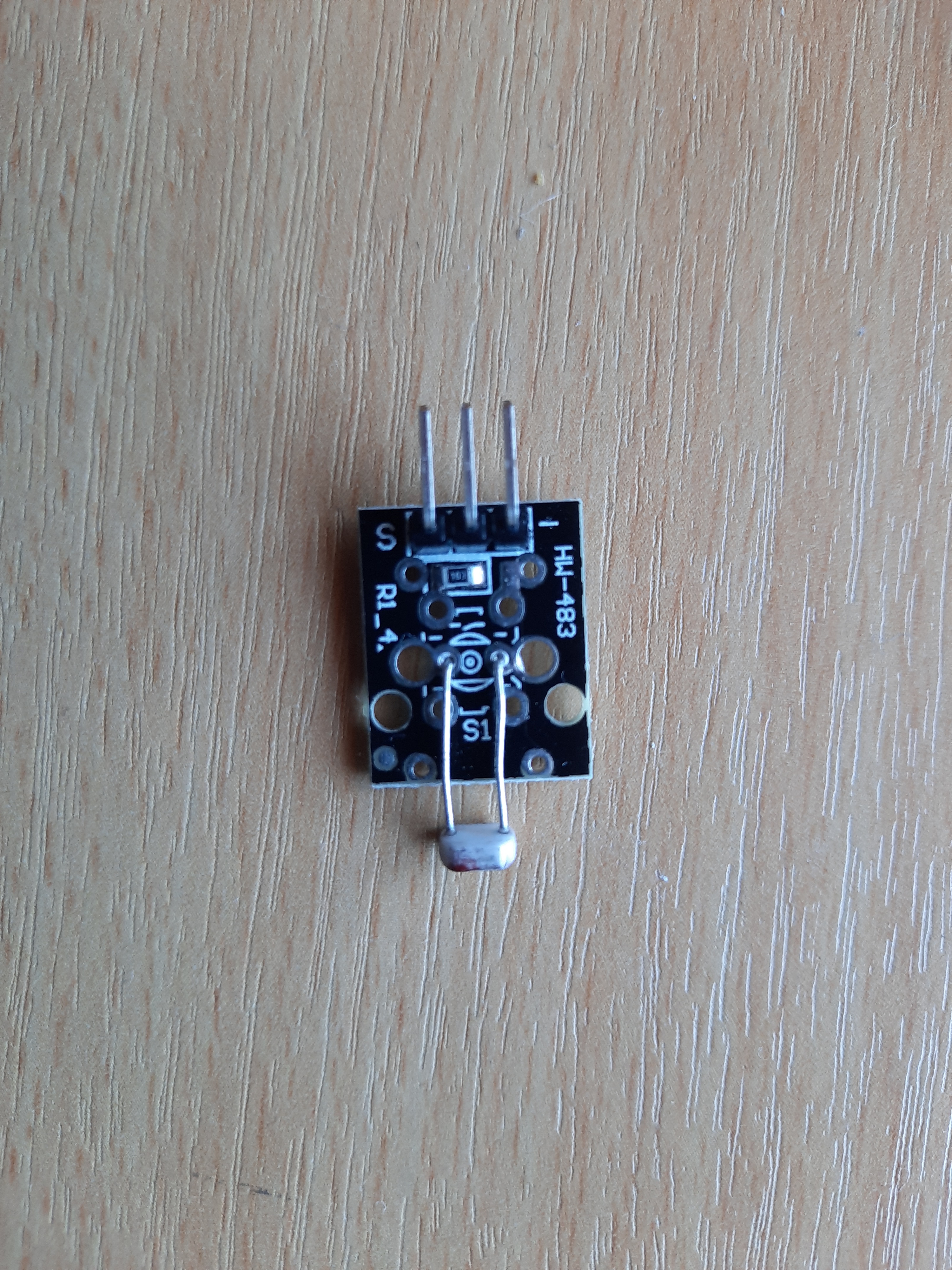
Light depended resistor:
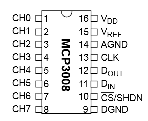
To get correct readings from the LDR I use a MCP3008 chip. This makes sure that the readings from the ldr are stable and correct converted from analog to digital signals.
Connect 3V3 to one side of the ldr with a resistor of 10K Ohm between it. Between the ldr and the resistor connect a wire to the channel 0 of the MCP3008. Then connect the other side of the ldr to the ground.
LCD display:
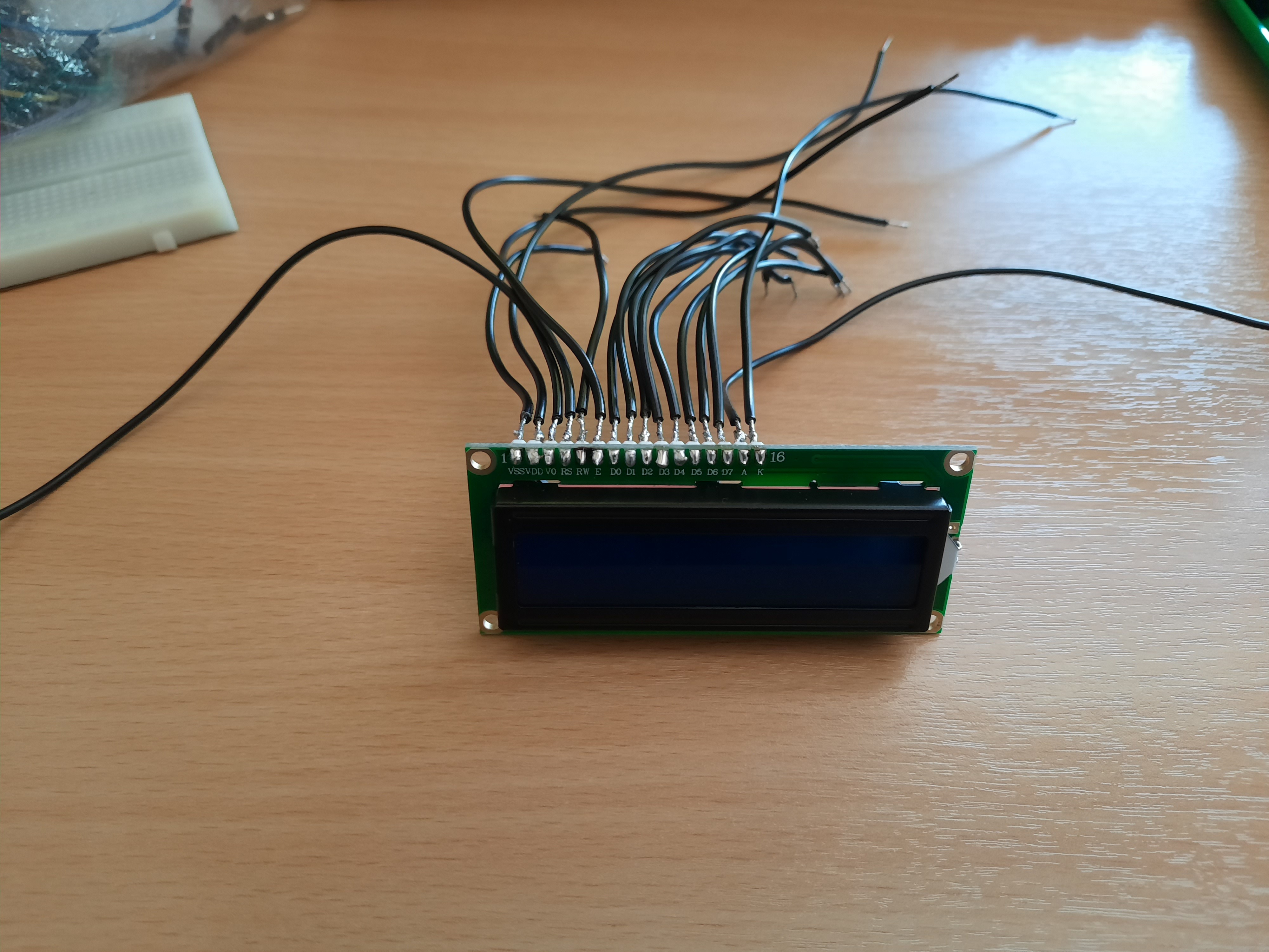
You can use the LCD display without a PCF8574 but because the GPIO pins on the Pi are limited I use a PCF8574 to save some GPIO pins. You can also use a shift register but I prefer a PCF8574. You can control the PCF8574 with the SMbus protocol but I wrote my own class to control it. The potentiometer controls the contrast.
LCD display pins:
- VSS to ground
- VDD to 5V
- V0 to the variable pin of the potentiometer
- RS to GPIO 13
- R/W to ground because I only write to the display and not read
- E to GPIO 19
- DB0 to P0 of the PCF
- DB1 to P1
- DB2 to P2
- DB3 to P3
- DB4 to P4
- DB5 to P5
- DB6 to P6
- DB7 to P7
- LED+ to 5V
- LED- to ground
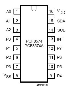
PCF8574 pins:
- A0 to ground
- A1 to ground
- A2 to ground
- Ground to ground
- VCC to 5V
- SDA to GPIO 27
- SCL to GPIO 22 with resistor of 330 Ohm
You may not have LED+ and LED- depending on what type of display you got. LED+ and LED- is for the backlight.
Connect the positive side of the potentiometer to 5V and the ground to ground.
Make sure you use Pull-up resistors!
Code on Github
You can find all the necessary code on my Github.
Folder project1:
This folder contains all the code for the backend. In the folder Klasses are all the classes to control the hardware.
The folder repositories contains 2 files: Database.py and DataRepository.py. Database.py maintains the connection to the database and handles queries. DataRepository.py contains all the queries needed for the site.
App.py is the main file of the backend. This file starts automaticly when the Pi boots.
Config.py contains a few settings to connect to the database. Make sure you fill in these files with your own information.
You can place this folder anywhere in your home directory.
Folder html:
This folder contains all the files for the site, the frontend.
- The folder contains the files for the layout of the site.
- Fonts contains the fonts used on the site.
- Script contains all the Javascript files to make the site dynamic
This folder has to be in the folder /var/www/html
You can copy a file or folder with this command:
sudo mv /path/to/current/directory /path/to/destination/directory
To navigate to the site type in your browser the IP-address displayed on the LCD display.
Normalised Database Structure
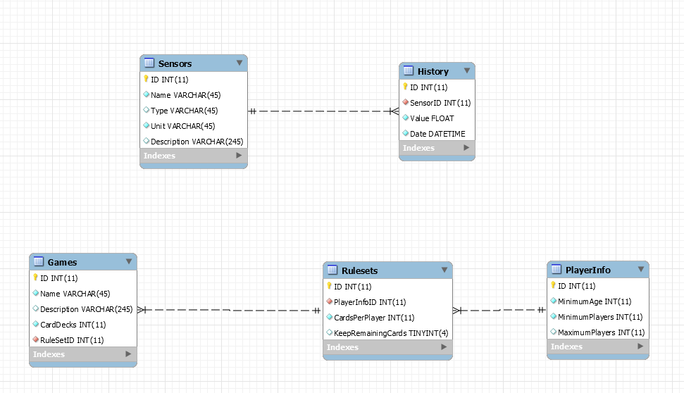
In this step we are going to import the database.
- Connect to your Raspberry Pi with MySQL Workbench
- Click on Server -> Data Import
- Select Import Self-contained File
- In the folder Database-export from Github there is a sql file called dump_project1.sql
- Browse to this file and click start import
That's it. The Pi can now access the database if it has the correct information.
Case for the Card Distributor
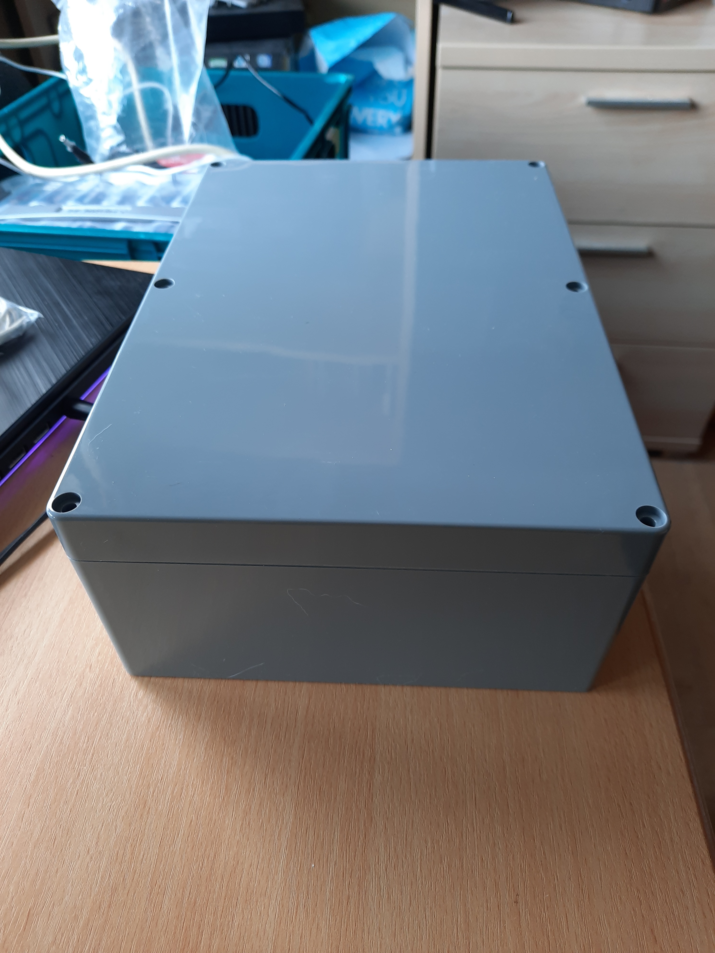
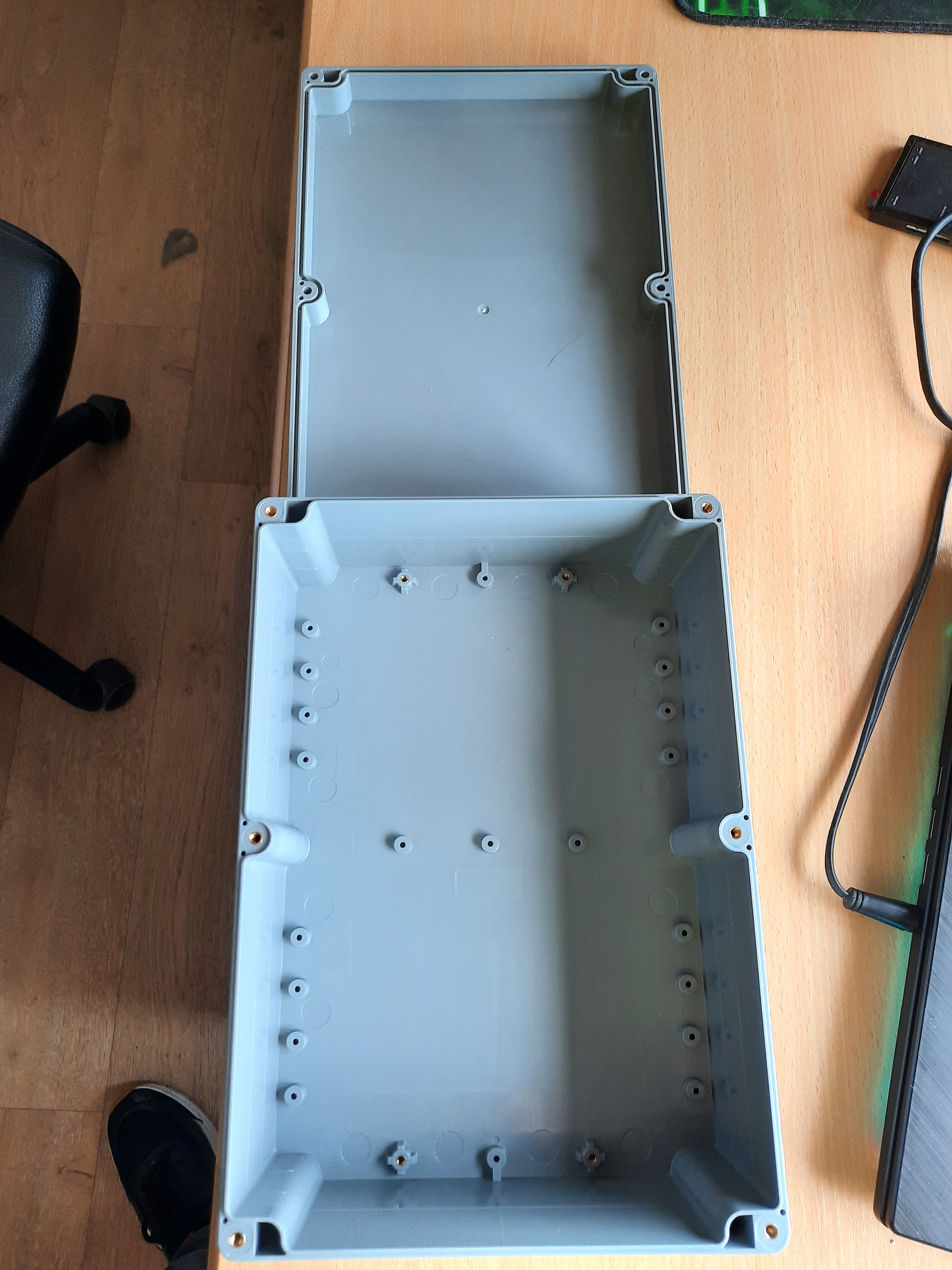
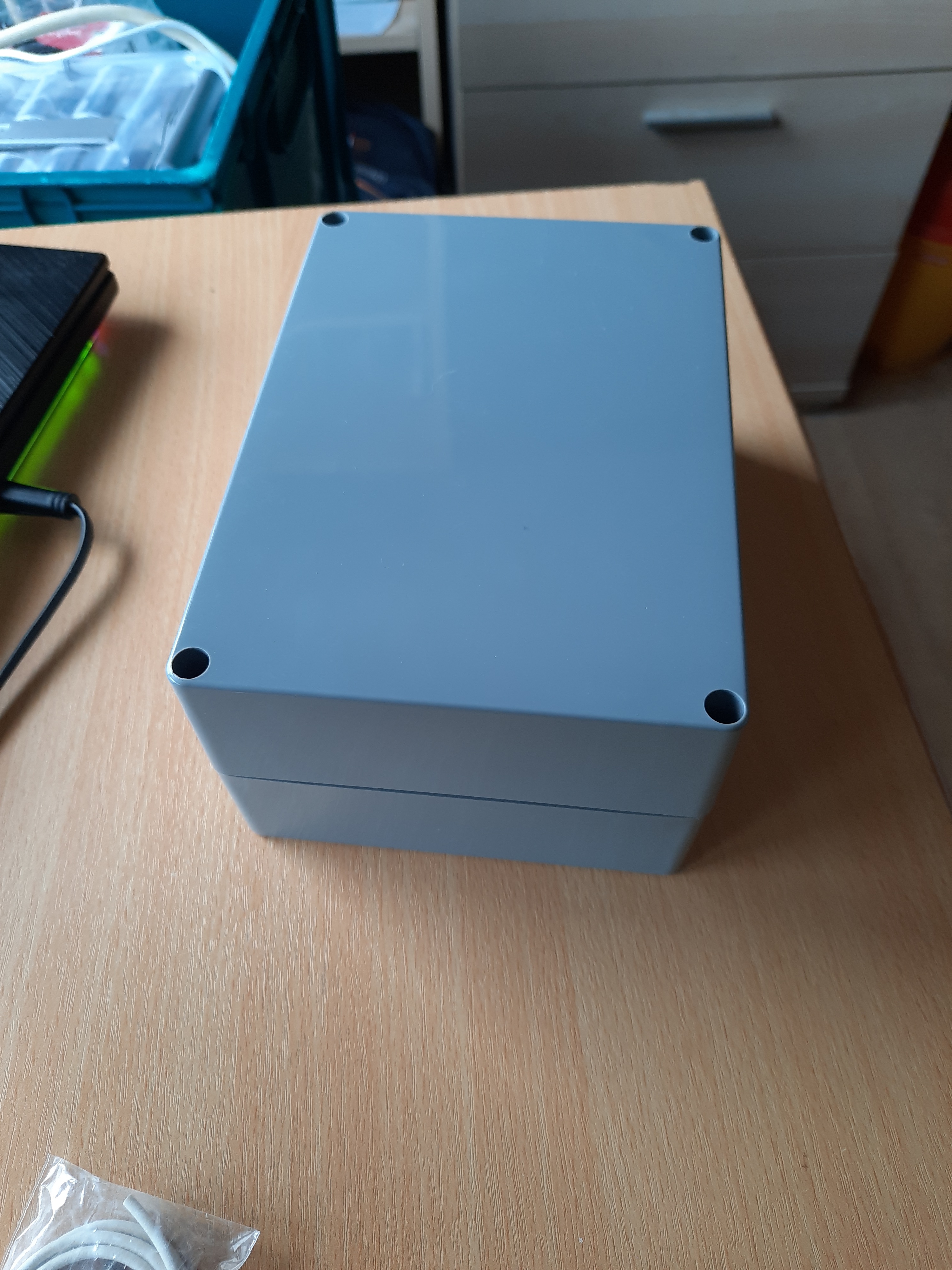
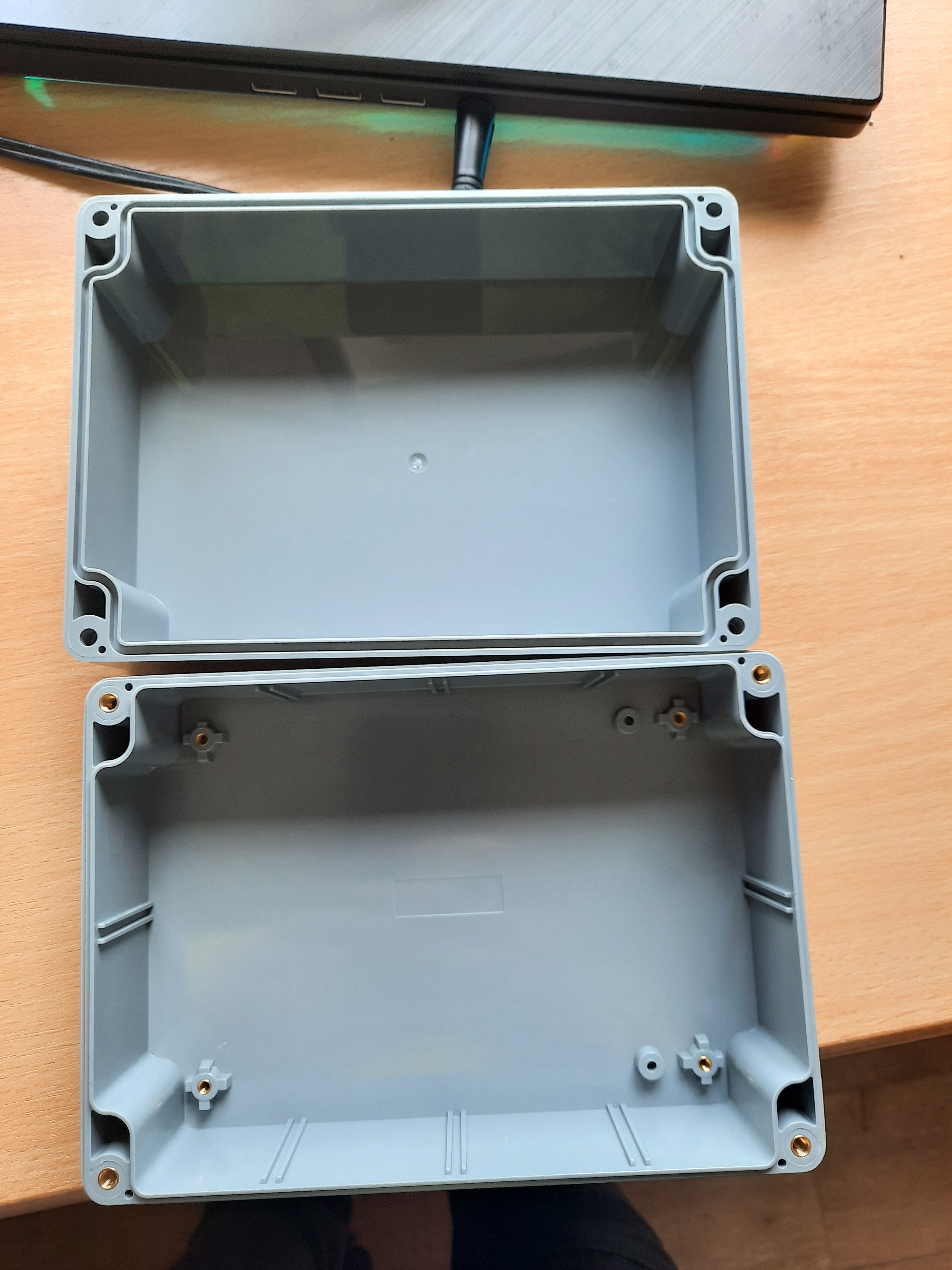
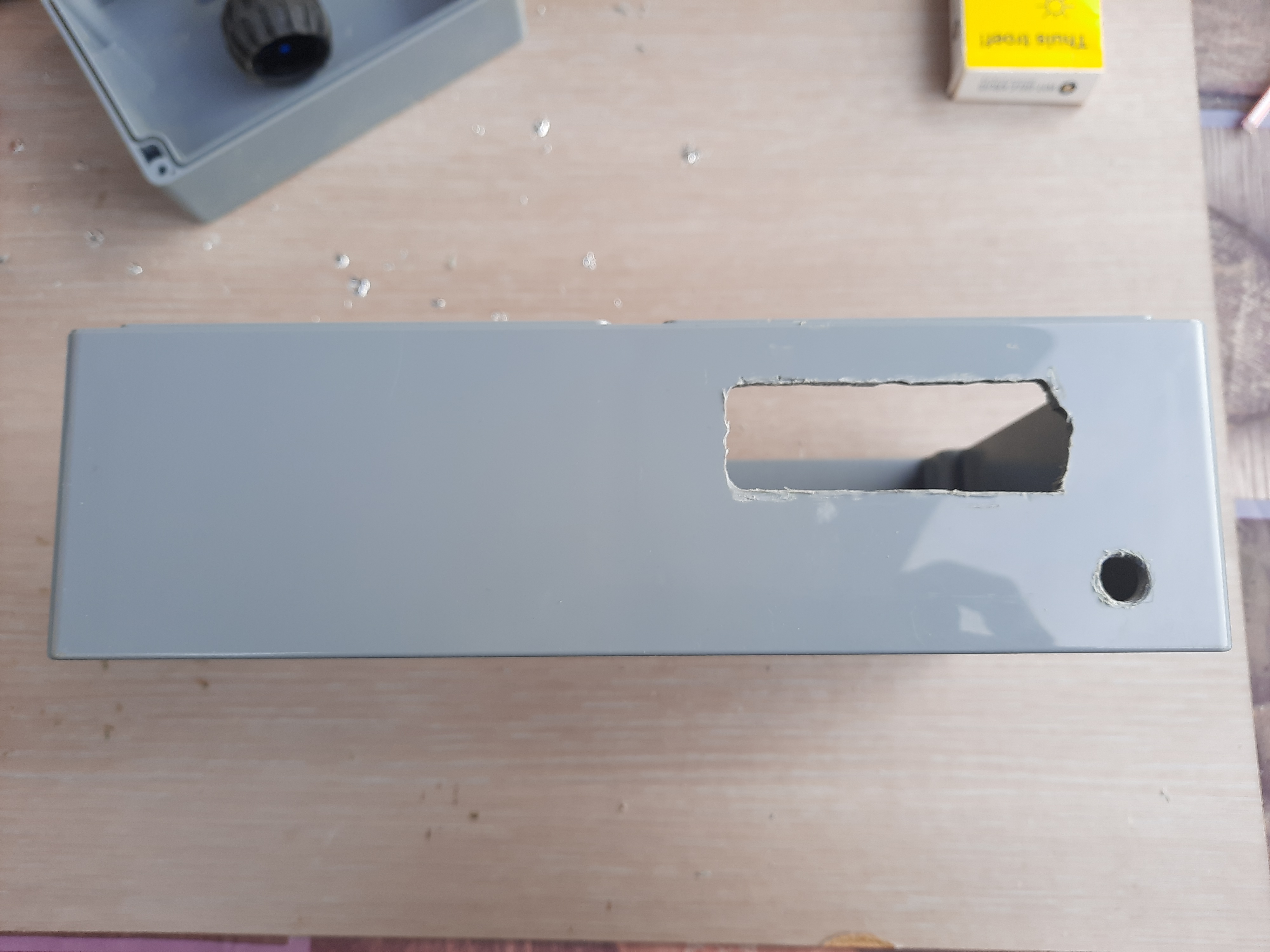
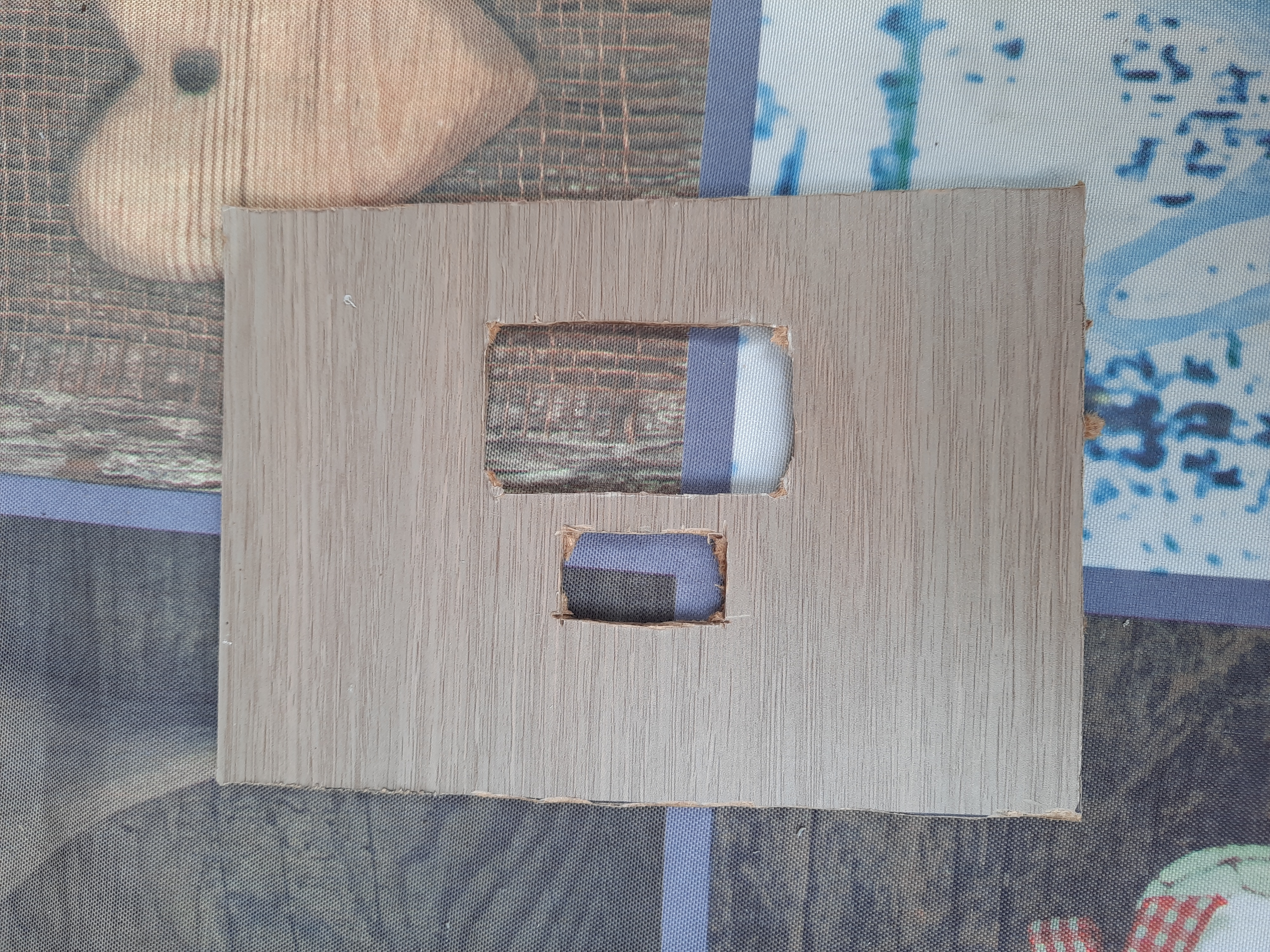
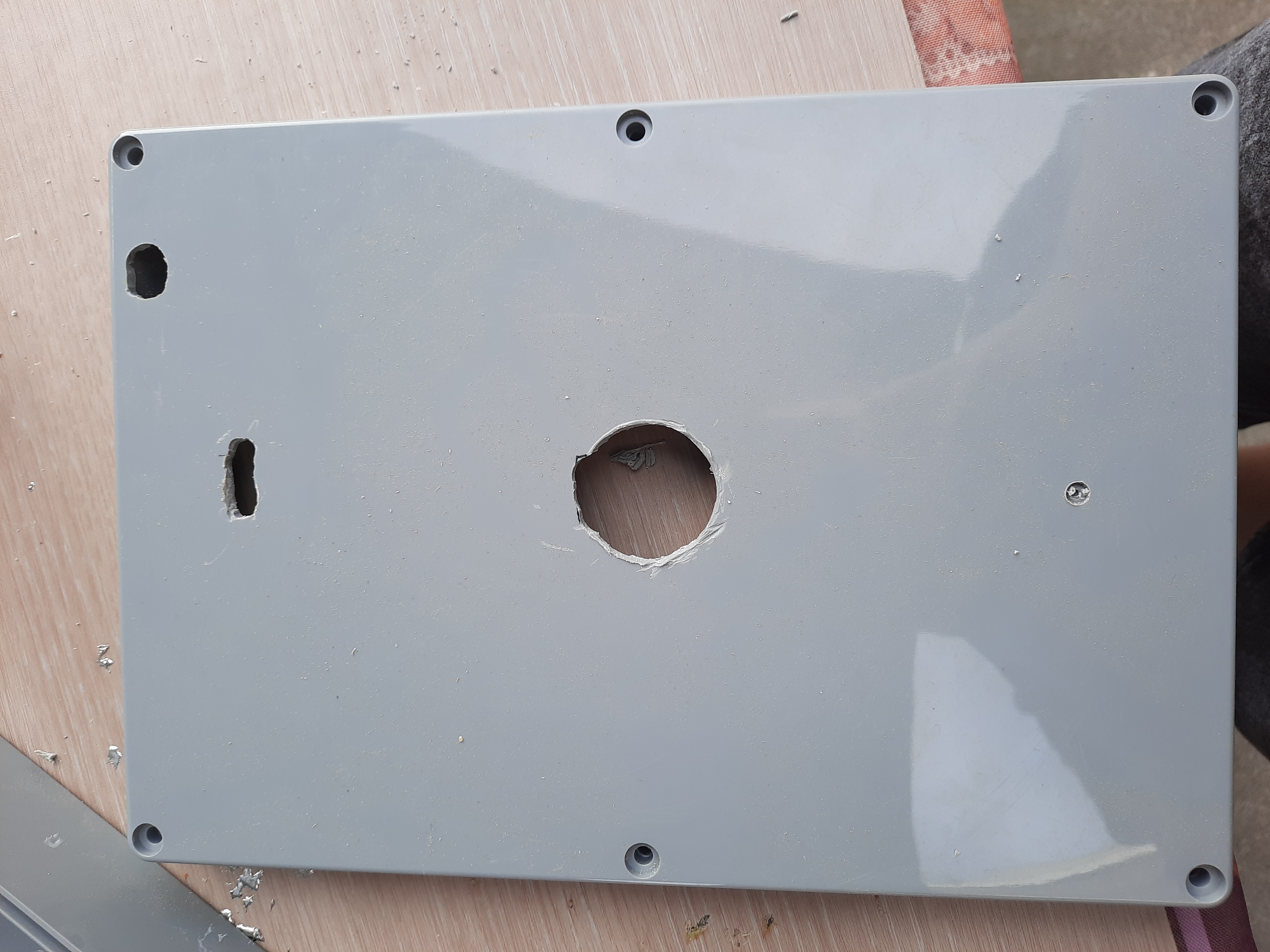
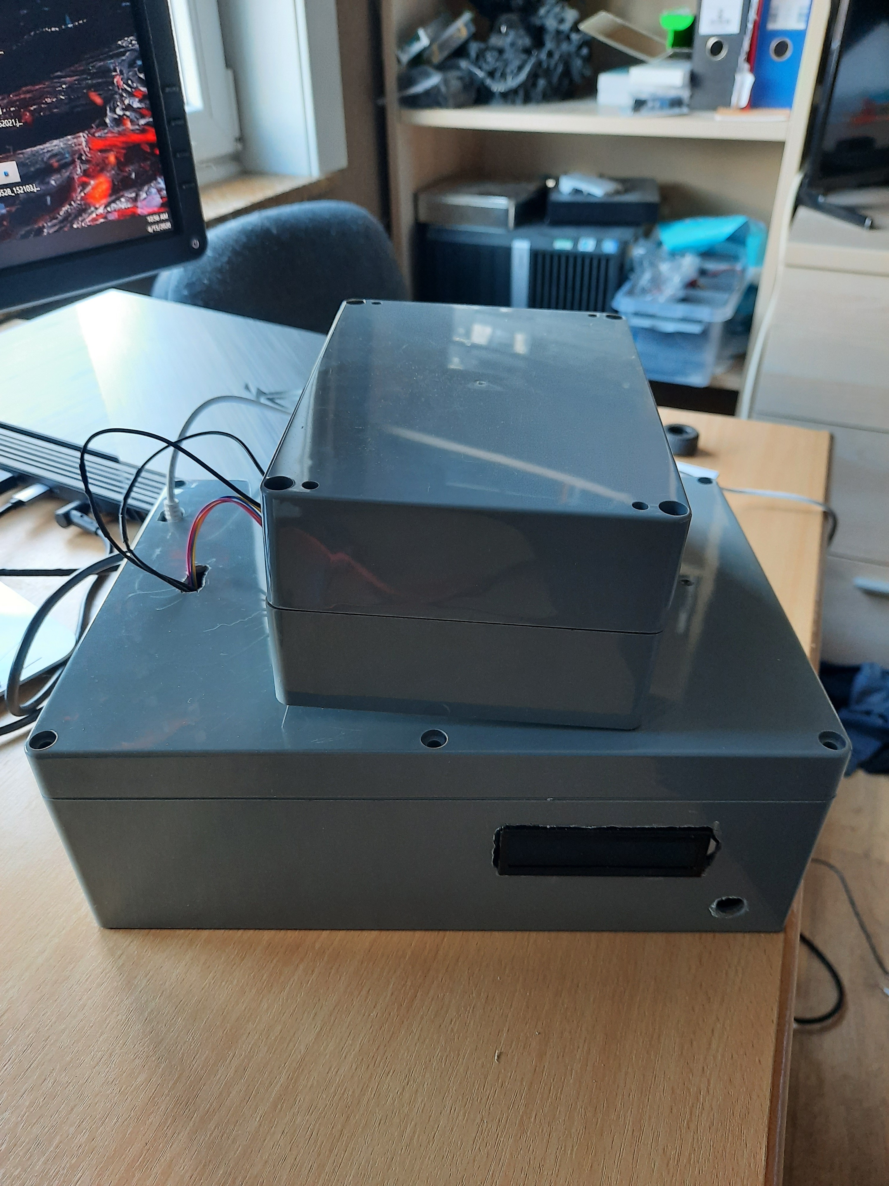
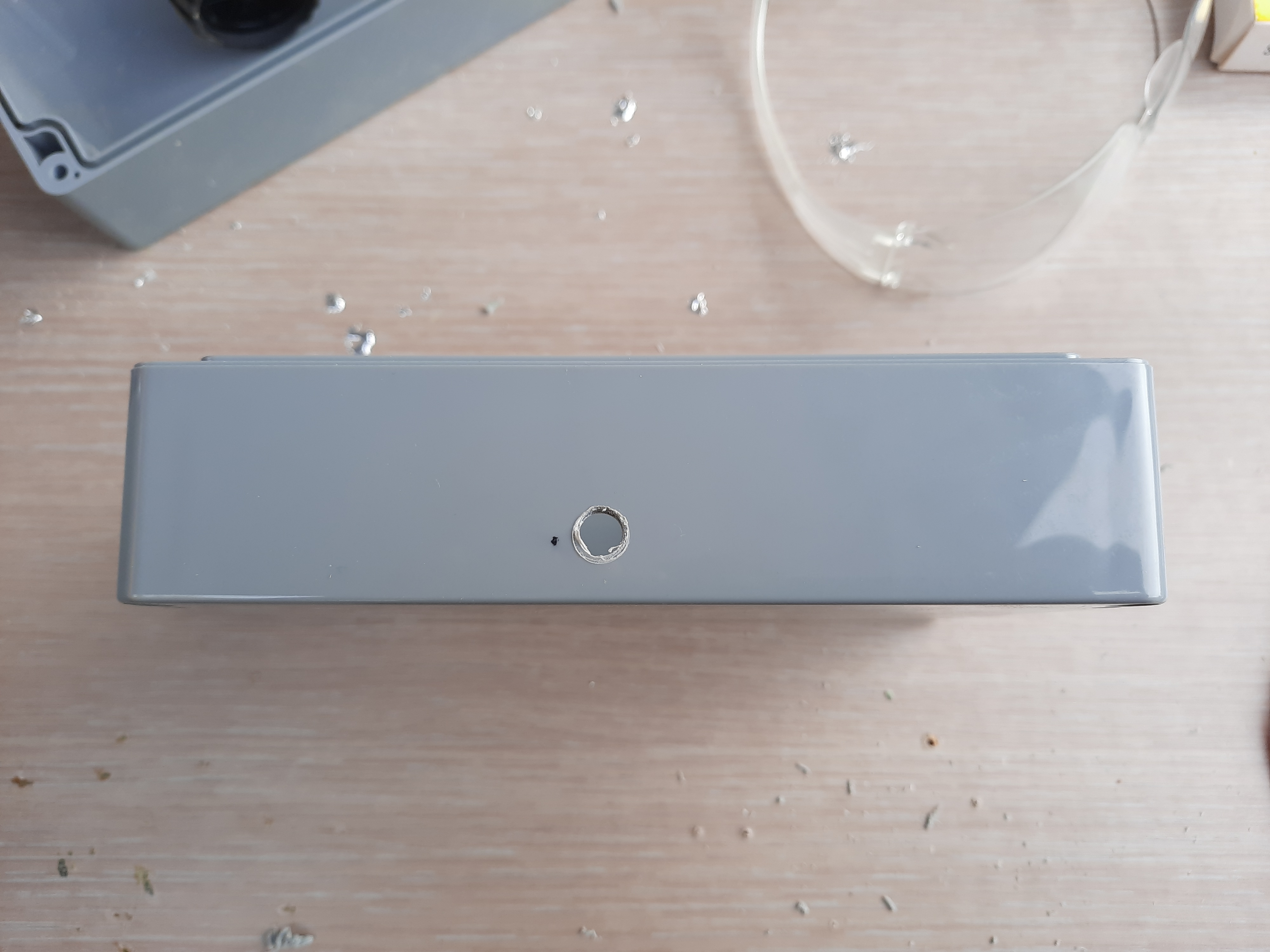
In this step I will explain what I used for the case and how I mounted everything.
For the case I used 2 ABS boxes:
- 265 x 185 x 95 mm
- 171 x 121 x 80 mm
The holes I made in the boxes
A hole for the LCD display, 3 holes for the power cables, one for the wires from the stepper motor, the DC motor and the ultrasonic sensor.
In the smallest box I made a hole for the wires from the components and a hole for the cards to pass through. In the top I made the biggest hole so you can place play cards in the device.
I mounted the DC motor with a bracket and some double sided tape. I made a wooden board to lay the cards on with a hole for the wheel to shoot a card.
I have chosen for ABS plastic because it is lightweight so the stepper motor can turn it easily. Wood can be really heavy and the stepper motor could have problems with this. To cut the holes I used a drill with drillbits designed for metal and a Dremel. Cutting the larger holes took a lot more work and a jig saw would be better.
Program As a Service
It is really usefull to have the code starting after the Pi is booted. For that we are going to make a service.
Create a new file called smartcard.service with the following command:
sudo nano /etc/systemd/system/smartcard.service
This has to go into the file:
[Unit]
Description=Smart card backend
After=network.target

[Service]
ExecStart=/usr/bin/python3 -u app.py
WorkingDirectory=/home/pi/project1
StandardOutput=inherit
StandardError=inherit
Restart=always
User=pi

[Install]
WantedBy=multi-user.target
Now you got your own Smart Card!