Automated Paint Can Opener
.jpeg)
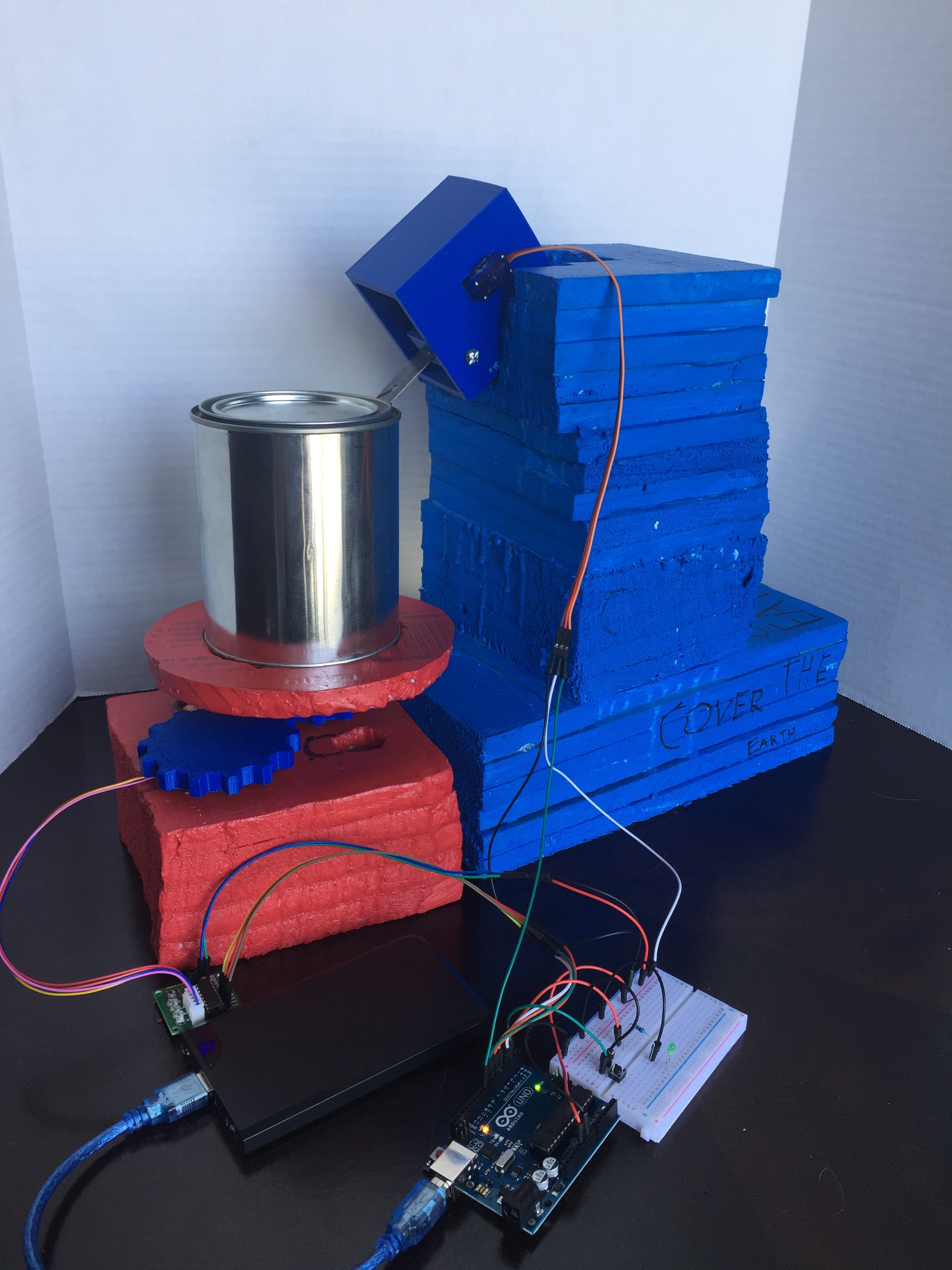
This instructable was created in fulfillment of the project requirement of the Makecourse at the University of South Florida (www.makecourse.com). In today's Instructable, I will be showing you how to create an automated paint can opener.
Step 1: Designing the Paint Can Opener
.jpeg)
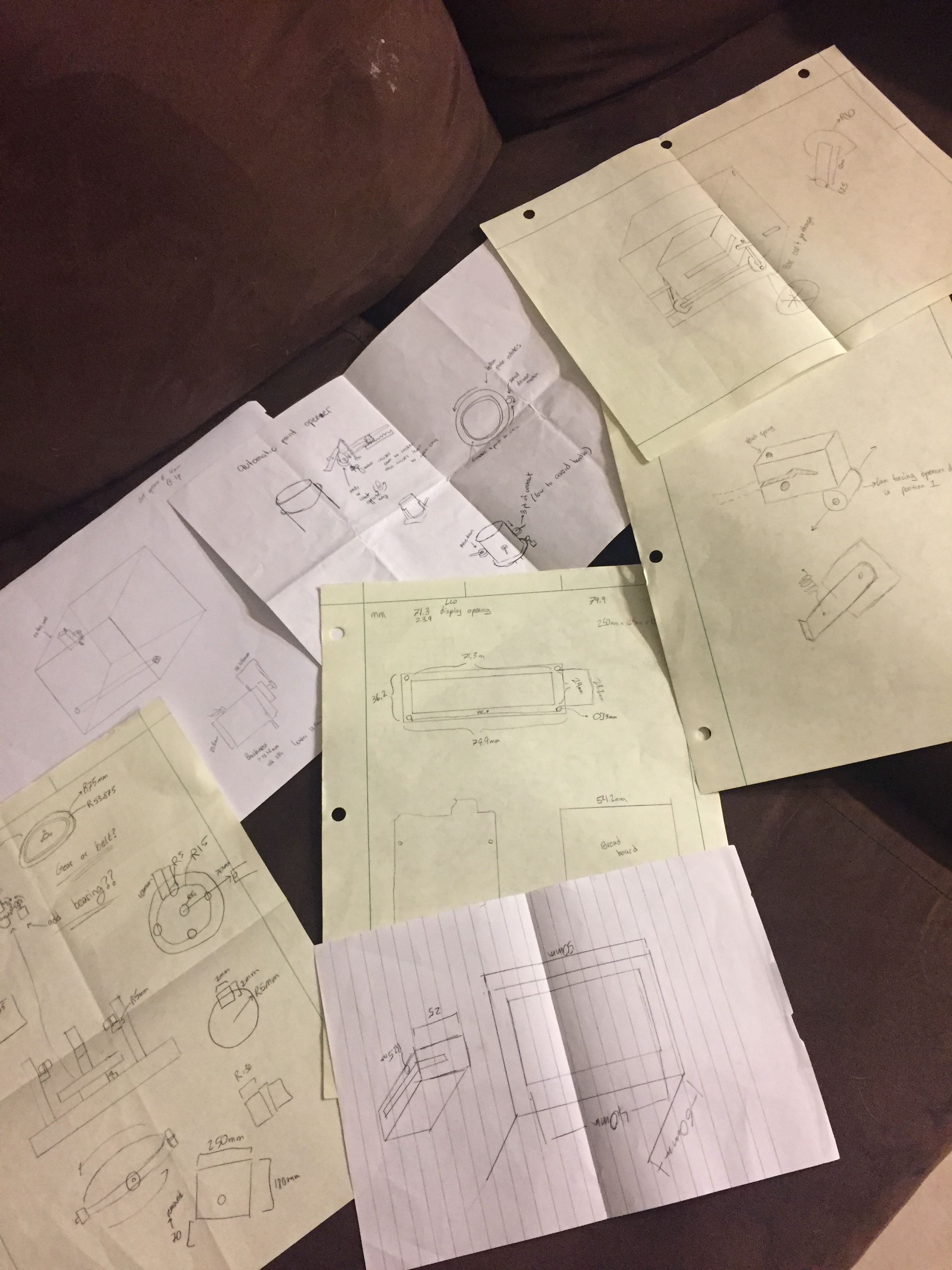
The first step in creating your automated paint can opener is to design and figure out what your overall game plan is. Some may wish to make a project out of wood, others may wish to 3D print, or maybe just Styrofoam/cardboard. The material dictates the stability of the project but some smaller spaces and limiting budgets may dictate the overall design and material that you may wish to use for the creation of your automated paint can opener. From here on out, I will use a mixture of 3D printed parts, styrofoam, and electronic hardware to create a automated paint can opener. Your designing process is most important in trying to make a general goal or plan that you wish to follow to achieve your goal with the limitations at hand. This step isn't easy and may take several attempts and drawings before you find a design that satisfies your limitations, but once you have an overall goal, it will make the rest of steps much easier to follow.
Step 2: Creating Your Arduino Circiut for Operation.
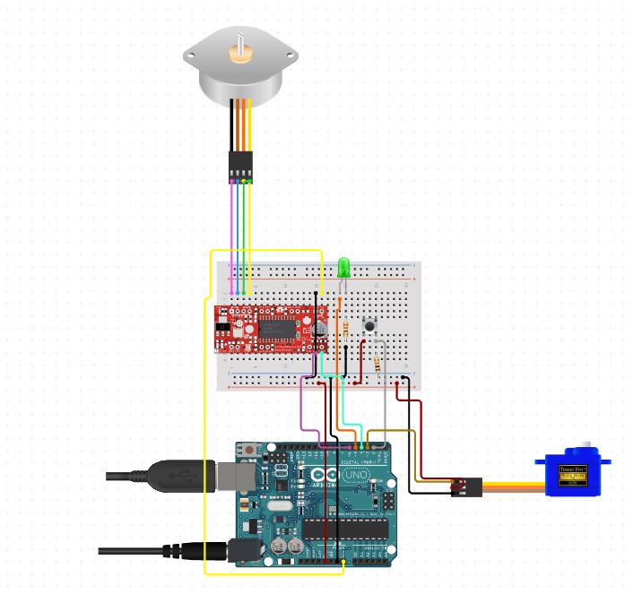
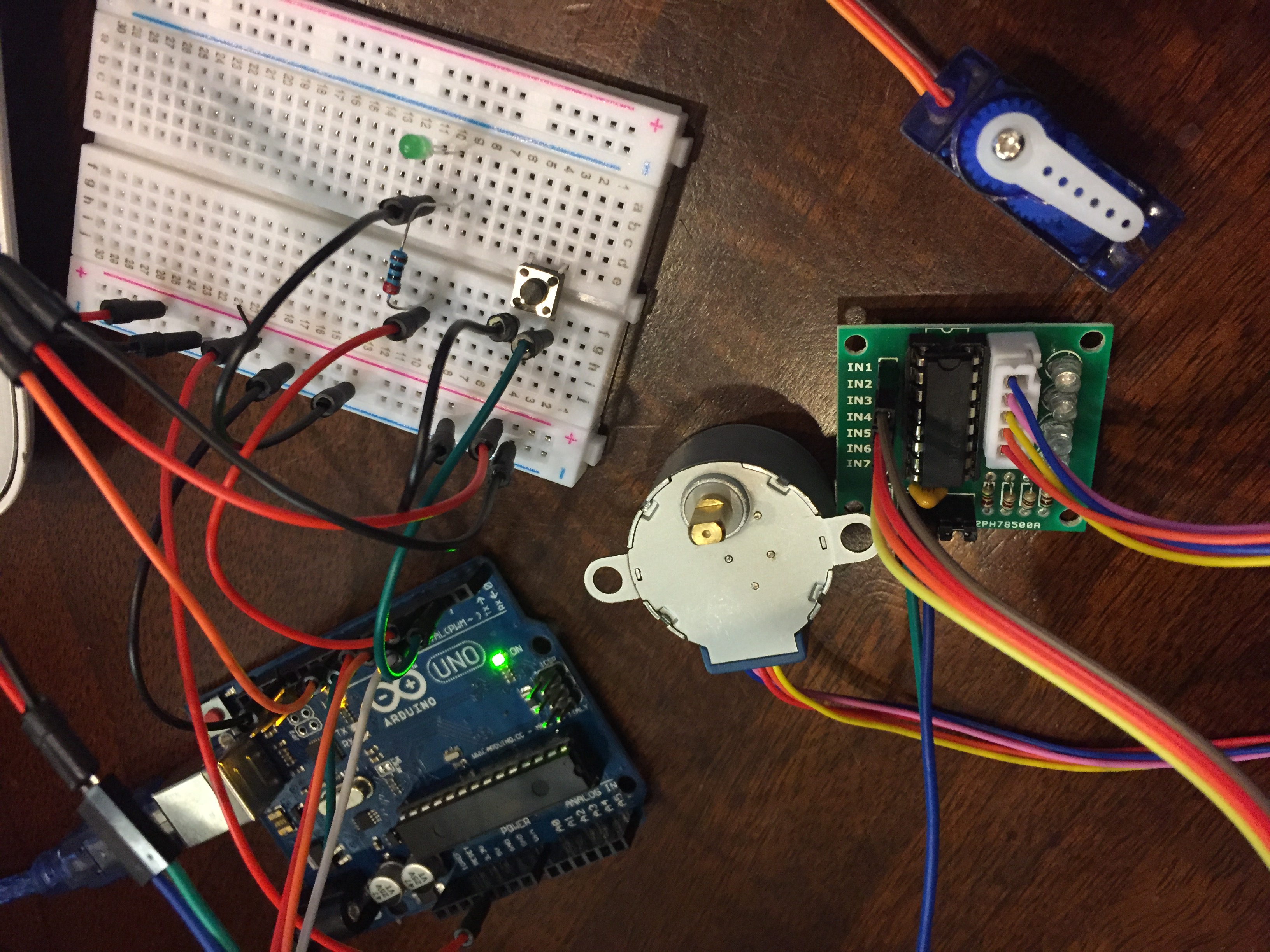
I'm starting with the electronic hardware set-up that I had selected for my automated paint can opener. I used an Arduino Uno as my main micro-controller that controls the overall operations of the project, a 9g micro servo motor that would operate the opening mechanism of my design allowing for repetitive motion of moving the servo arm from 0 to 90 to 0 to 90 etc. , a 5V stepper motor that controls the rotation motion of the paint can through a gear system, a couple 220ohm resisters that allow the button and light to function, a 1/2 breadboard (a full breadboard can be used but for reducing space I selected a 1/2) that allows you to connect everything, a handful of Dupont/jumper Wires to wire together all the components, a ULN2003A driver that controls the operation of the stepper motor (the circuit photo uses an EasyDriver - Stepper Motor Driver but either would work), a 5mm green LED, a mini push switch (button), a USB A to B cable to connect to your computer, and a 5V DC 2200mAh battery power supply that supports power to the Arduino so it may operate the uploaded code that I will describe later.
Step 3: Writing the C+ Code for Operating the Arduino
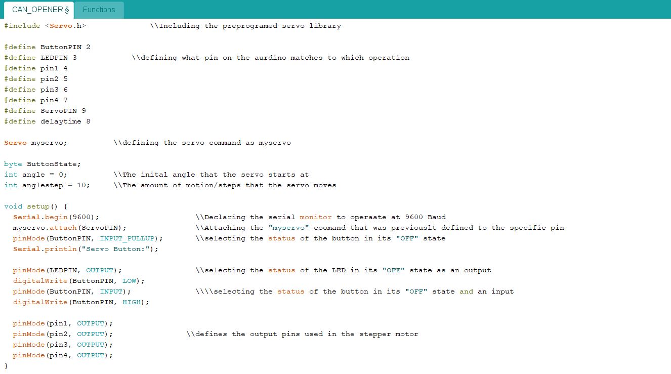


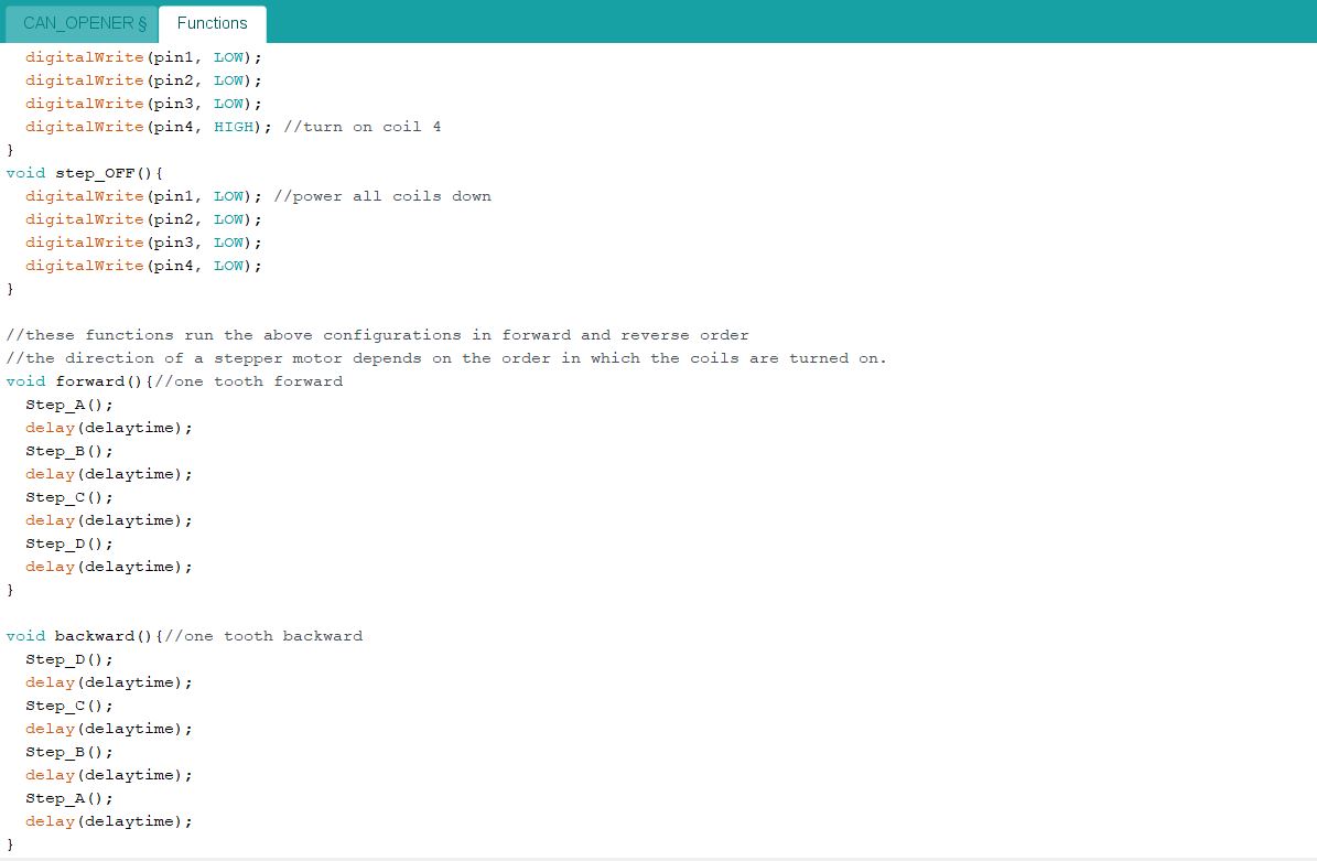
In the following pictures I have the the code I created for operating the circuit setup that I had shown in the previous step. The function library can be downloaded at the www.makecouse.com tutorial for operating the stepper motor that I had used. The code itself overall is made to start a continuous loop once the initial button is pressed on the breadboard. Once the button is pressed, the green LED light activates to signify that the automated paint can opener is in operation. The servo motor and the stepper motor run in unison with the stepper motor operating the torsional motion of the base-plate that the quart size paint can sits on, and the servo operating the opener that uses a lever action and resistance to a spring that allows the opener to pry the lid off the paint can. The reset button on the Arduino Uno stops the operation until the button is then pressed again. Upload this code (or a similar code you have created) to the Arduino using the A to B USB cable. Once the program is uploaded, remove the USB from your computer, and attach to a battery pack or power source to supply power to the unit from here on out.
Step 4: 3D Printing Any Necessary Parts
.jpeg)
.jpeg)
.jpeg)
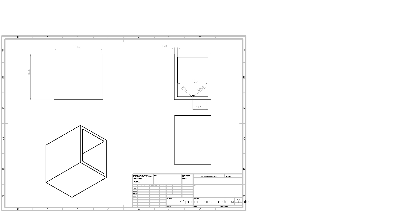
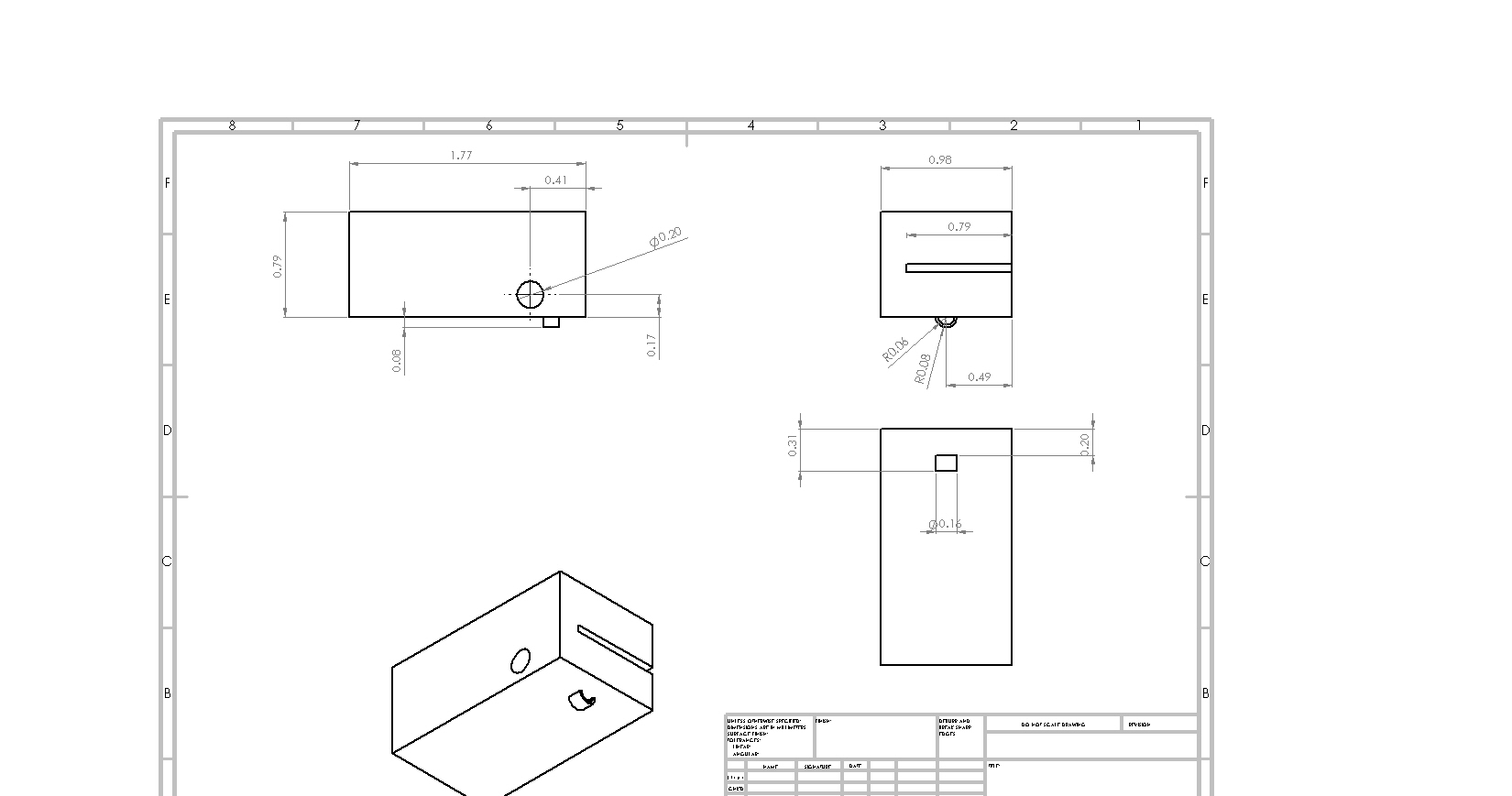
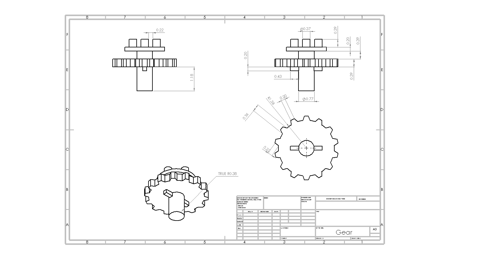
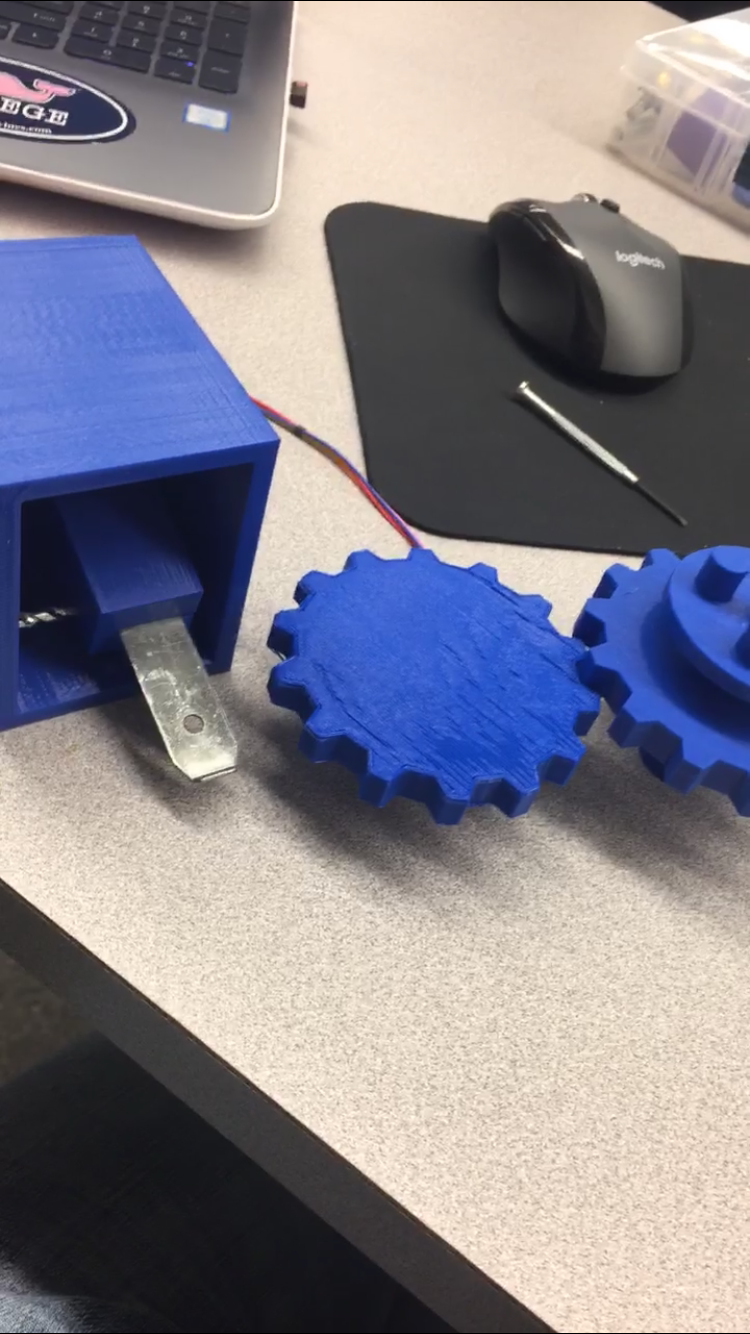
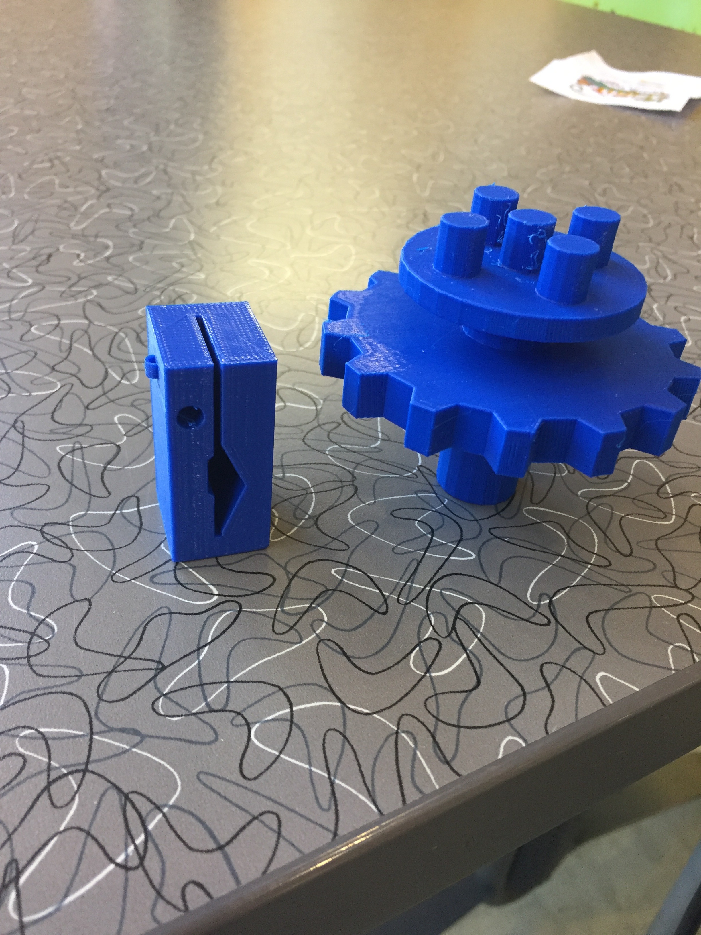
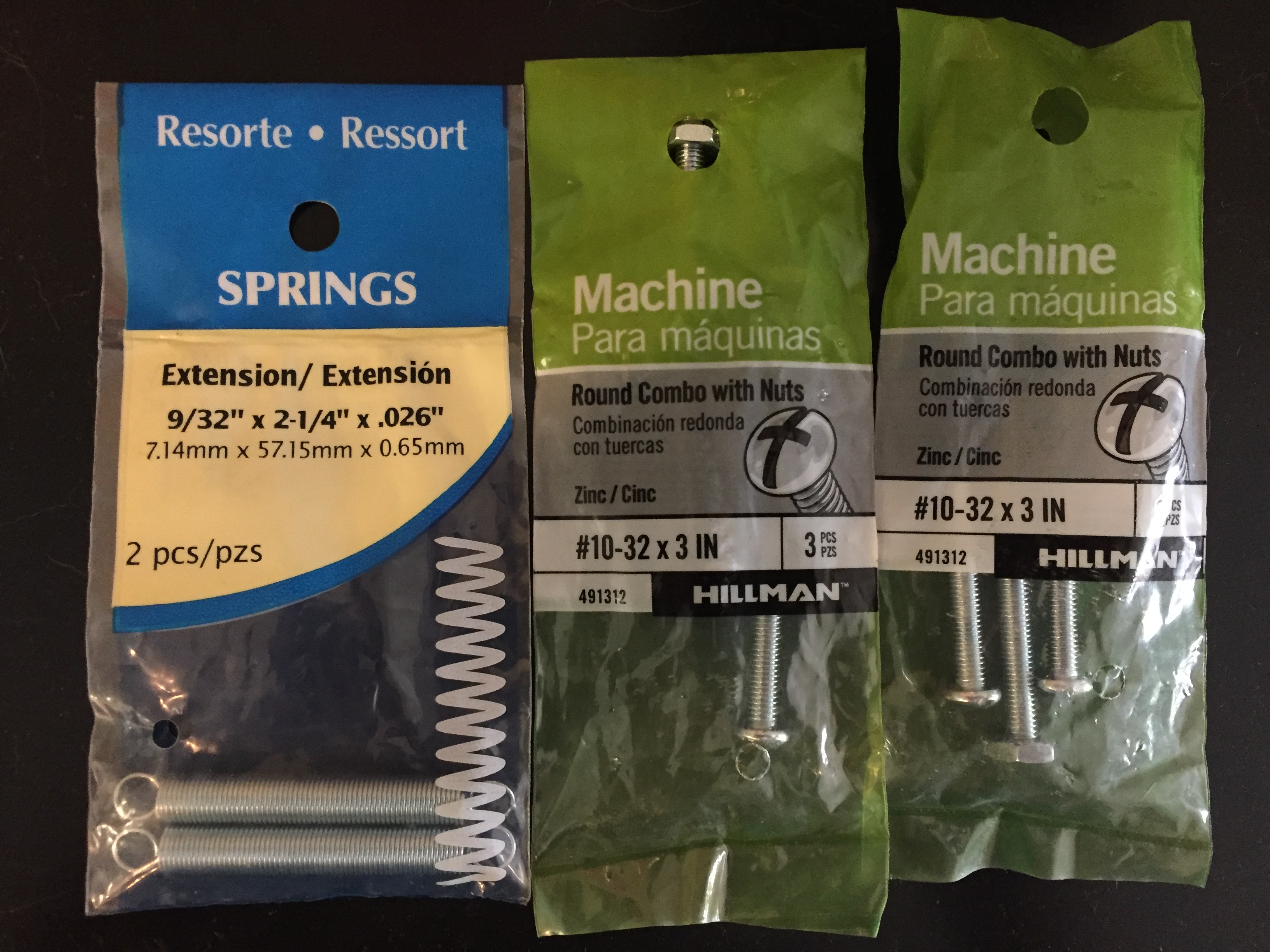
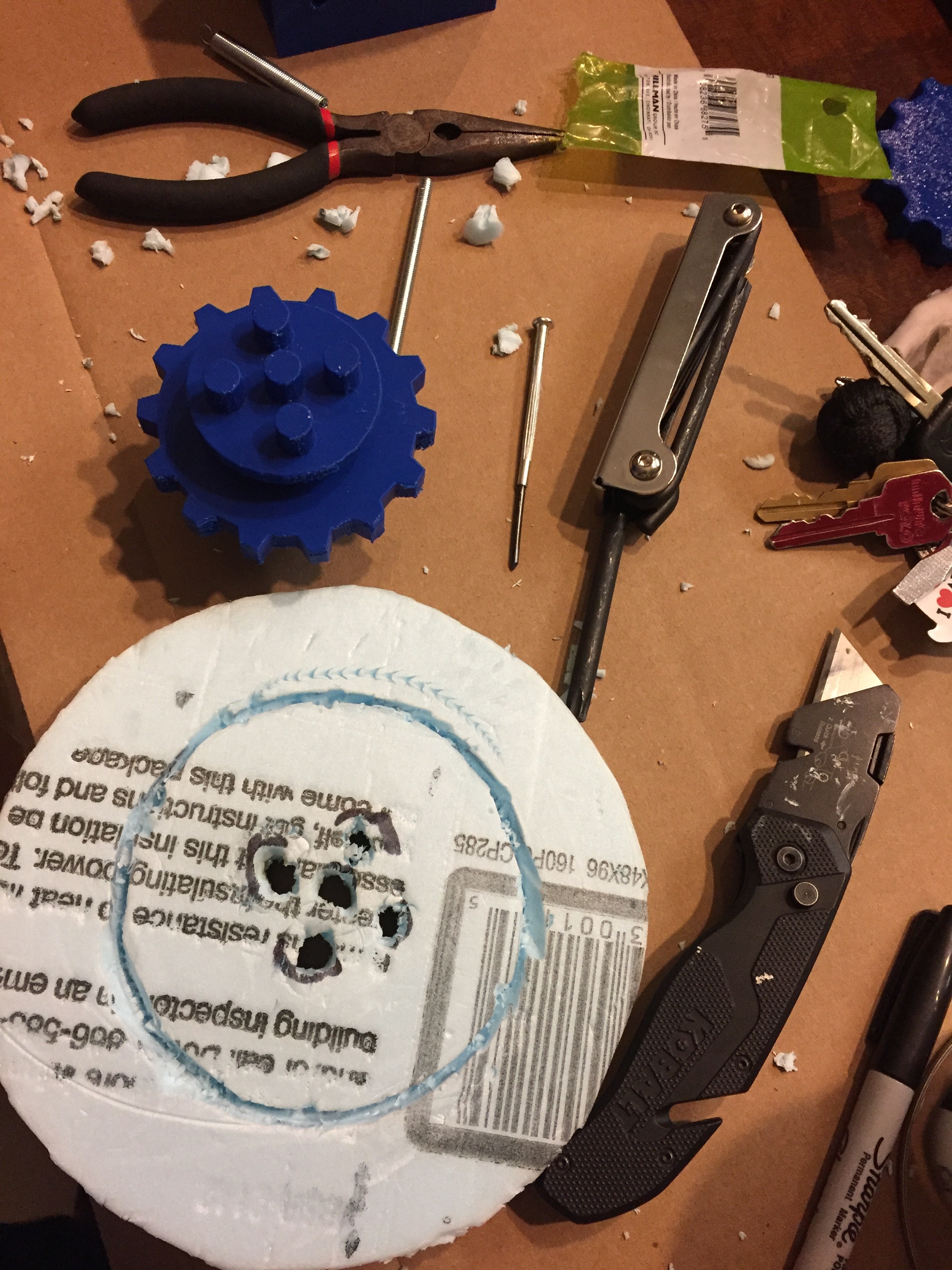
I printed a total of 4 parts for my automated paint can opener. The first part is a holding container that will hold the opening mechanism and servo motor. The second part being the opener itself that fits the basic can opener that can be acquired at any Sherwin-Williams Paint store free of charge. The last 2 being the gear system that operates the base plate that the paint can will rest on. The first gear that's pictured above being a gear/stand that connects to a base-plate and a second gear that controls the rotation of the paint can.The second gear that is located on top of the stepper motor can be printed using the same gear that is shown above. The opener operates against an extension spring pictured above and is fastened by the machine screws that are pictured above as well. A servo motor is attached to the side so it runs in unison with the codes operation that previously has been stated. The base-plate I constructed was using simple insulation Styrofoam found at my local Lowe's with a diameter of 6 1/2" and an inner diameter of 4". The quart size paint can will sit snugly in the grove with wht base-plate and the holes in the middle are to connect the gear/stand to the base-plate. Later on I paint the base-plate red for aesthetic purposes only.
Step 5: Creating the Stand and Base of the Project
.jpeg)
.jpeg)
.jpeg)
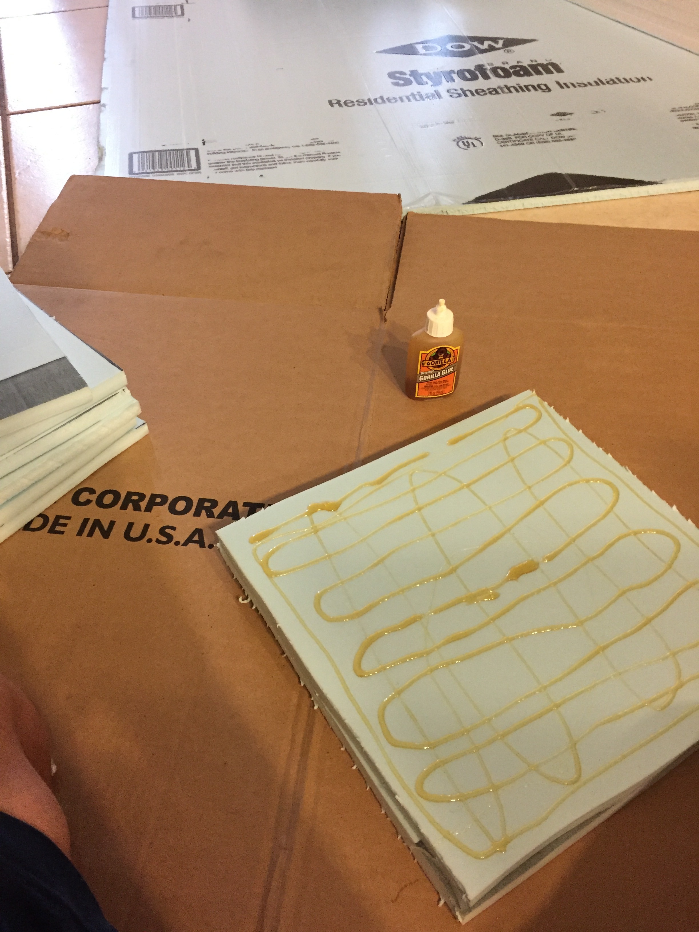
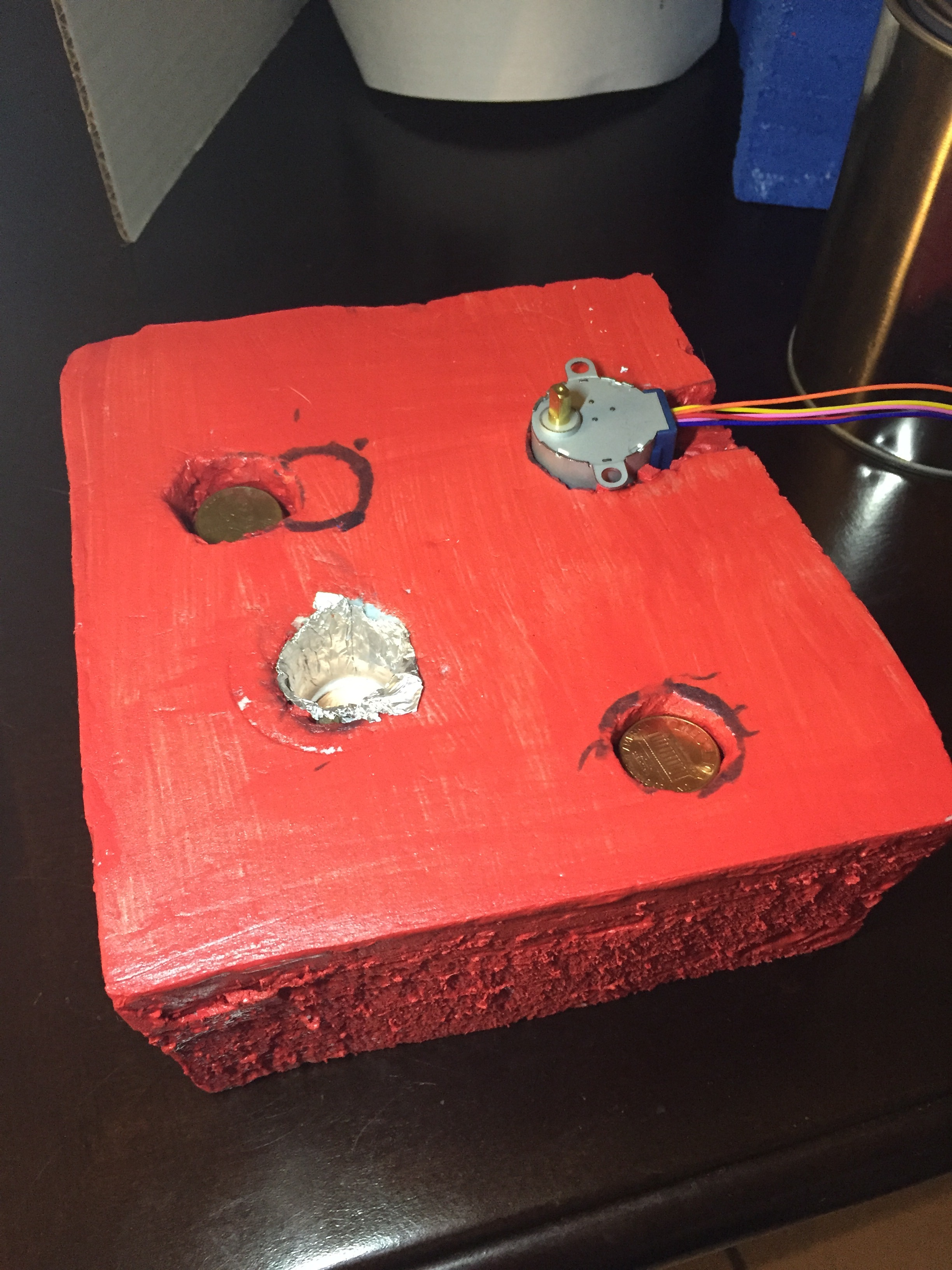
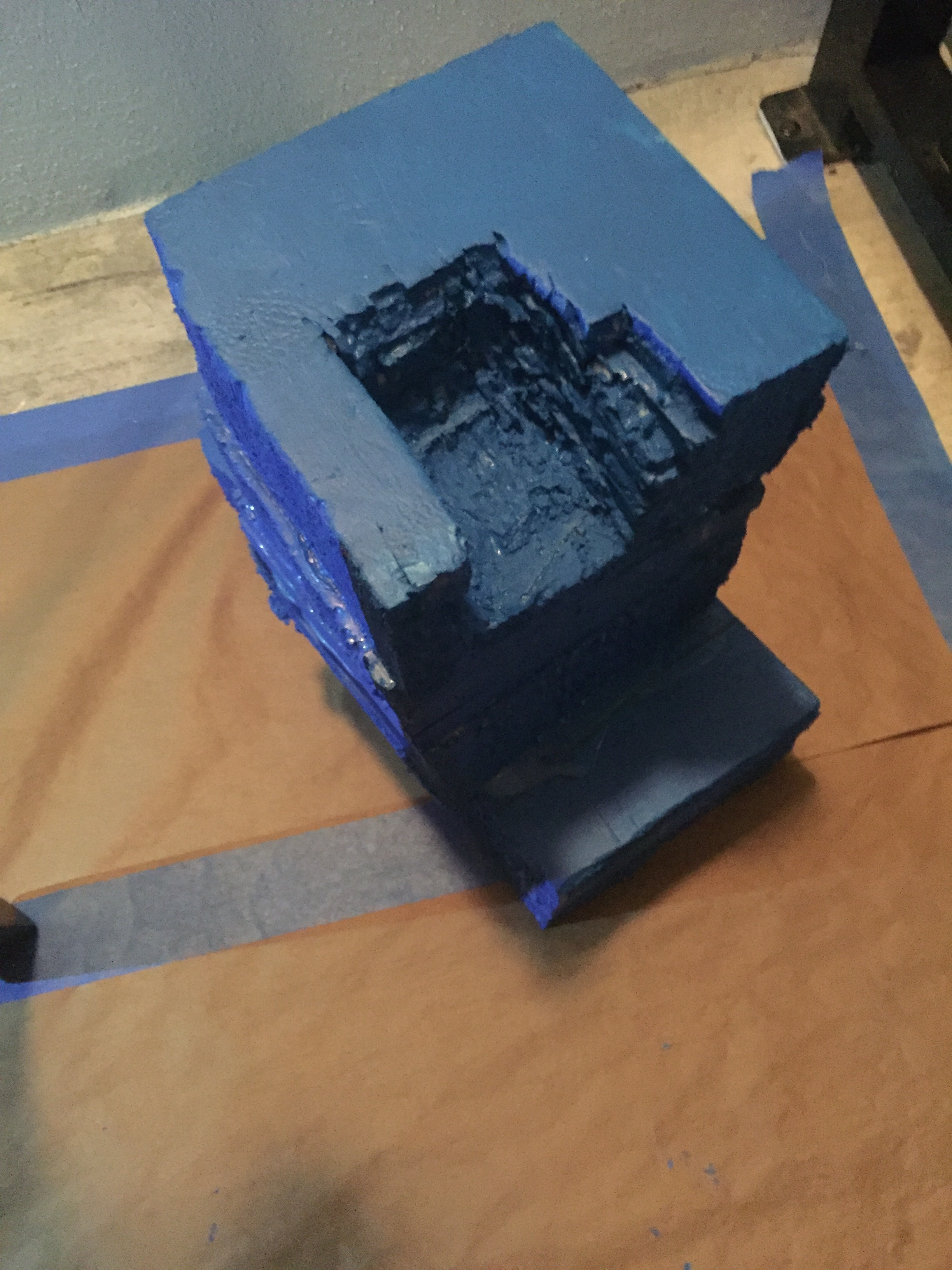
First making the base that the rotating base-plate will sit in, and the stepper motor slides into. I made a structure by gluing Styrofoam on top of each other and allowing the glue to harden before cutting into the desired shape using a simple hack-saw blade that I had purchased at my local Lowe's. (I didn't have the saw itself so just held the blade in a rag to allow me to cut the Styrofoam). I cut the box to be a square shape of 6 1/2" and a thickness of 3". The .9" diameter hole that the base-plate and gear/stand rests in is 3" distance from the stepper motor. Placement of the stepper motor and opener is up to your design but must be 3" for the gears to run smoothly if you used the same dimensions I had used. I added extra holes to add weight to hold the structure down that I filled with pennies and added a aluminum foil lining to the hole in which the base plate sits to decrease the coefficient of friction between the 3D printer gear stand and the box. Also this allowed me to add lubricants if needed to smooth the operation but aren't needed. I would recommend 3D printing the entire body but with my time constraint and available materials, Styrofoam was all I could manage. The stand is 13" high and 6 1/2" wide with a 2" gap that allows the opener to make contact with the quart size paint can perfectly. I added an extra 3 1/2" extension to the base for added support for the stand but may be unnecessary if you are concerned for space This may need some adjustments depending on your personal design. I then cut a 2 1/2" wide hole that's 4" long and 2 1/2" deep where the holding container will fit snugly. I removed a 1/2" extension on the right side of the hole to allow the servo motor to fit properly in place. I painted the structures for display purposes but that isn't necessary.
Step 6: Assembly All Electrical Components and Created Pieces.
.jpeg)
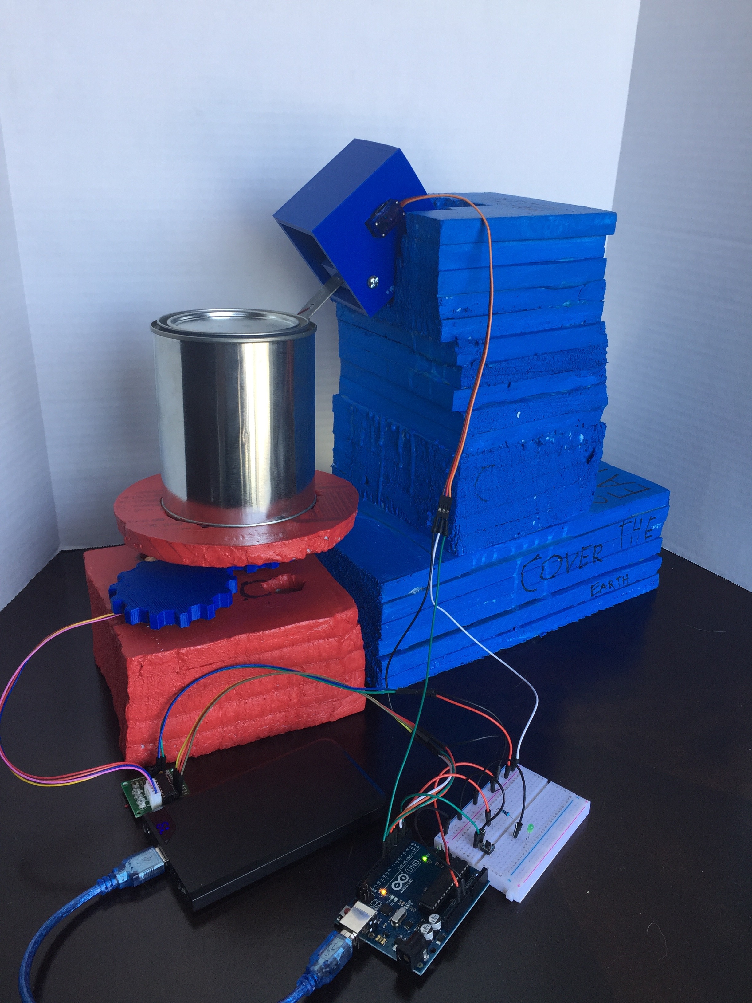
In this step, it depends on your specific design. I slid the opener holding container in the hole that I had cut on the top of the stand. I also added the stepper motor with its corresponding 3D printed gear. The 3D printed gear/stand that connects to the stepper motors gear and holds the base-plate. With this I set up the Arduino circuit that I had described earlier by connecting the stepper motor to the ULN2003A driver and the servo motor to the breadboard/Arduino. With this I tested the rotation and movement of the assembly and made slight adjustment changes to work faster and more smoothly (adding lubricants, opening holes wider, etc.). I added the opener that I had received at any Sherwin Williams paint store and an empty quart size paint can with fluids to demonstrate the operation of a full unopened can of paint. The opener should move in a vertical fashion to use a lever mechanic to pry the lid off the paint can. The stepper motor runs the gear system in unison to to revolve the quart sized paint that sits on the base-plate so the opener allows the lid to fully be removed. Once you have assembled your automated paint can opener with its corresponding electronic Arduino circuit setup, make any adjustments needed, and your final project should be a completed automated paint can opener.