Automated Model Railroad Layout Running Two Trains (V2.0) | Arduino Based
by KushagraK7 in Circuits > Arduino
9480 Views, 28 Favorites, 0 Comments
Automated Model Railroad Layout Running Two Trains (V2.0) | Arduino Based
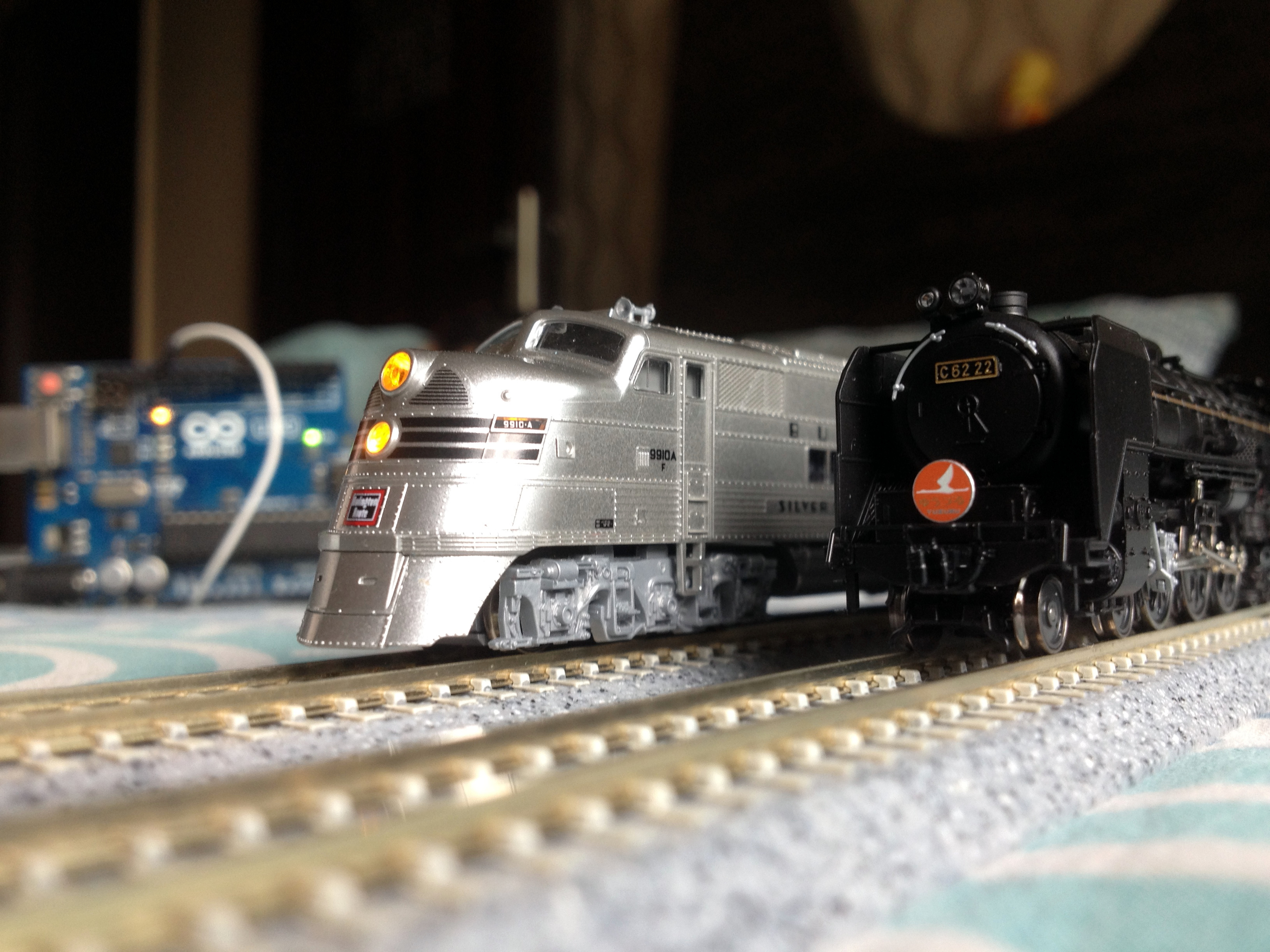
Automating model railroad layouts using Arduino microcontrollers is a great way of merging microcontrollers, programming and model railroading into one hobby. There are a bunch of projects available on running a train autonomously on a model railroad but after some time, a single train starts to get a bit boring. So, to populate our layout, let's get one more train and get started!
Watch the Video
)
Watch the above video to get an idea of how this works.
Get the Parts and Components
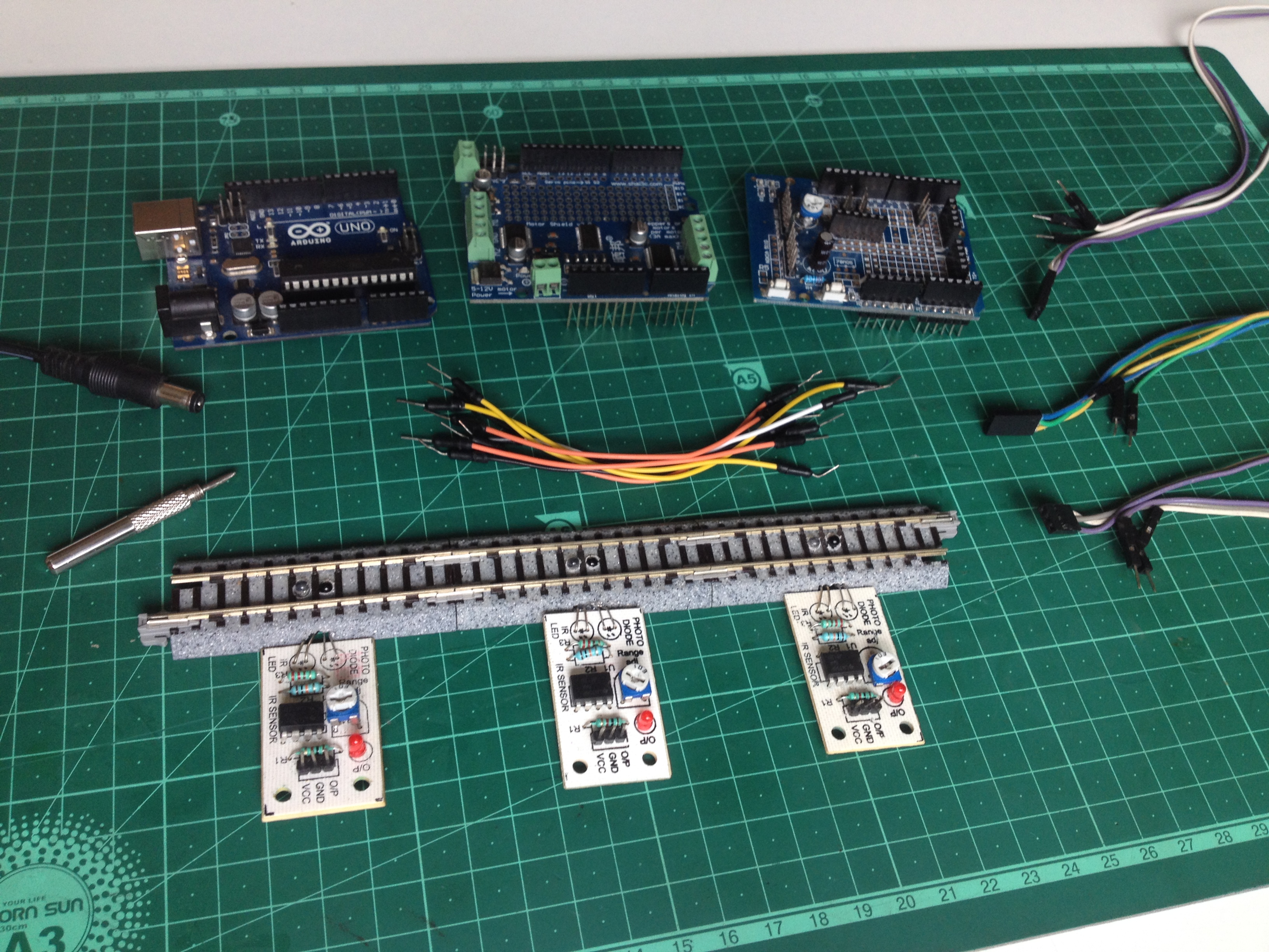
Here is what you will require for this project:
- An Arduino microcontroller board compatible with the Adafruit motor shield.
- An Adafruit motor driver shield v2.0.
- An expansion shield(Optional, but highly recommended to make wiring simpler.)
- 3 'sensored' tracks.
- 8 male to male jumper wires (For connecting track power and turnouts to the motor shield.)
- 3 sets of 3 male to female jumper wires (For connecting 'sensored' tracks to the Arduino board.
- A 12-volt DC power source with a current capacity of at least 1A(1000 mA).
- A suitable USB cable for connecting the Arduino board to a computer.
- A computer.
Program the Arduino Micorocontroller
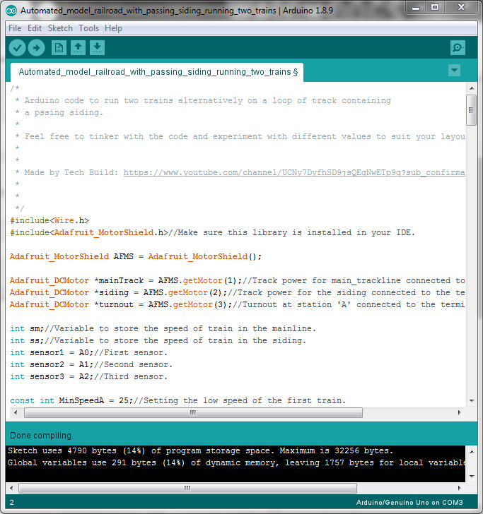
Make sure you have the Adafruit's motor shield v2 library installed in your Arduino IDE, if not, press Ctrl+Shift+I, search for the Adafruit motor shield and download the latest version of the Adafruit Motor shield V2 library.
Before uploading the code on the Arduino microcontroller, make sure to go through it to get an idea of what all is happening and how.
You can learn more about the motor driver shield here, but be sure to come back to continue the project!
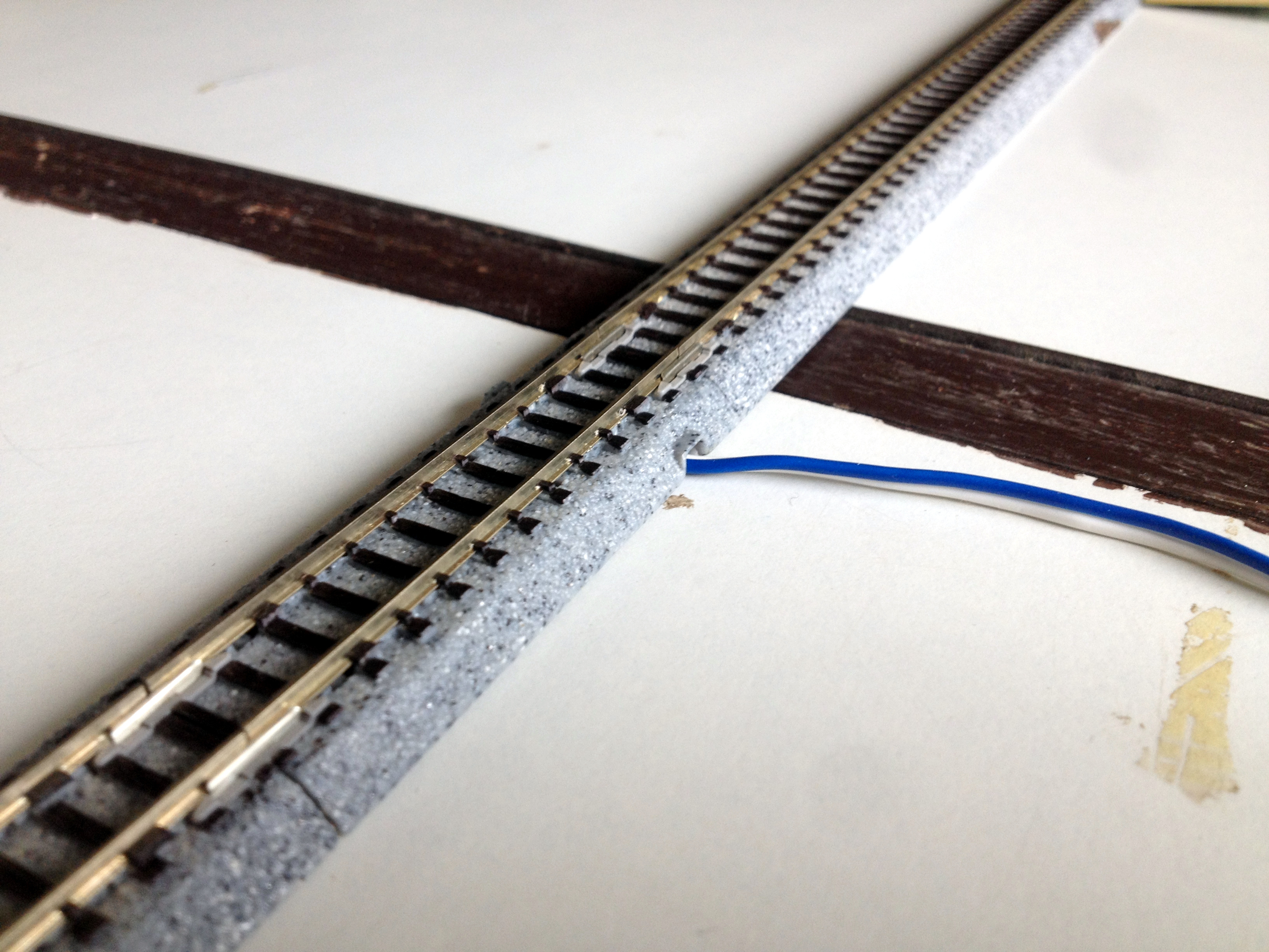
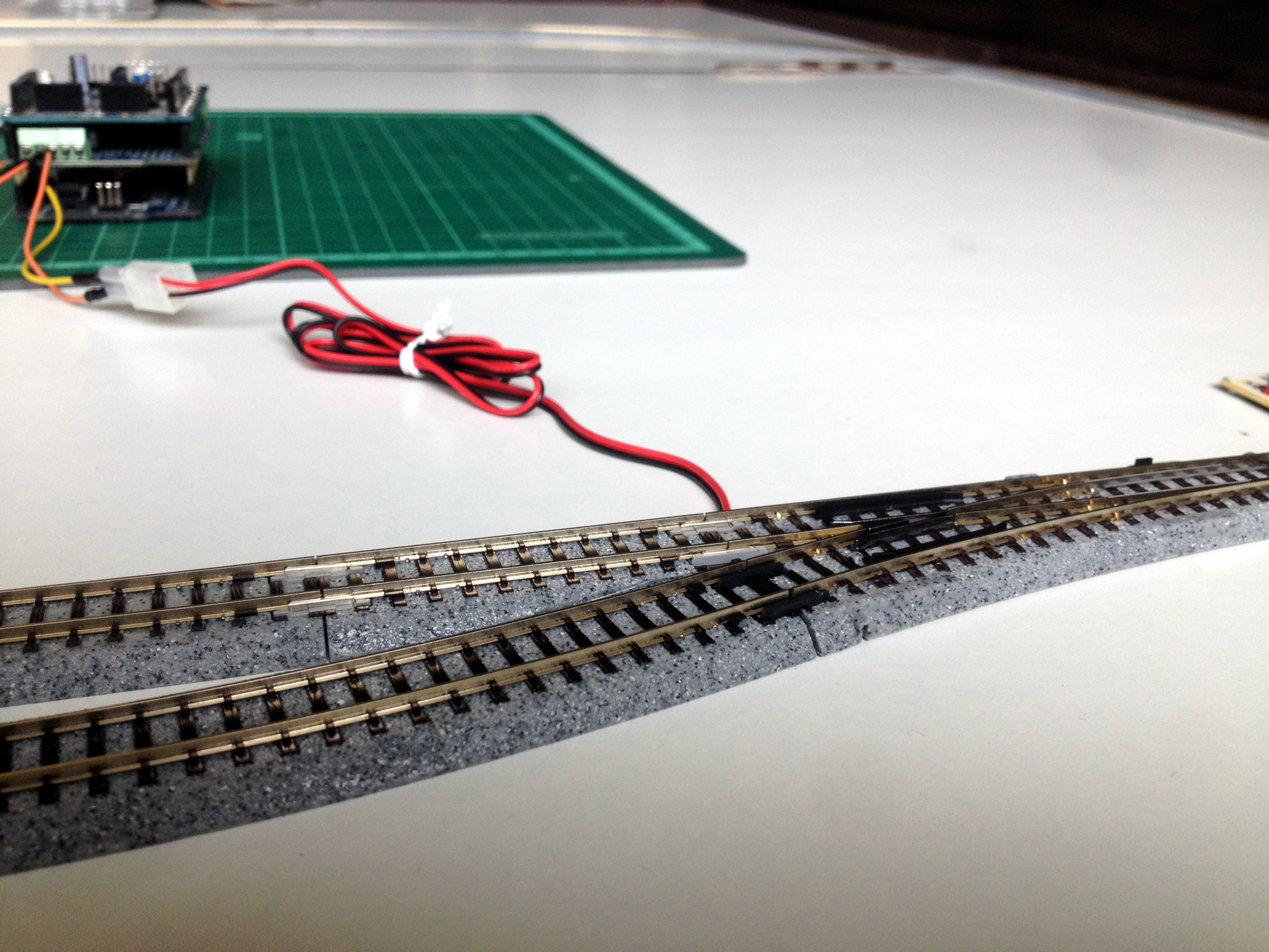
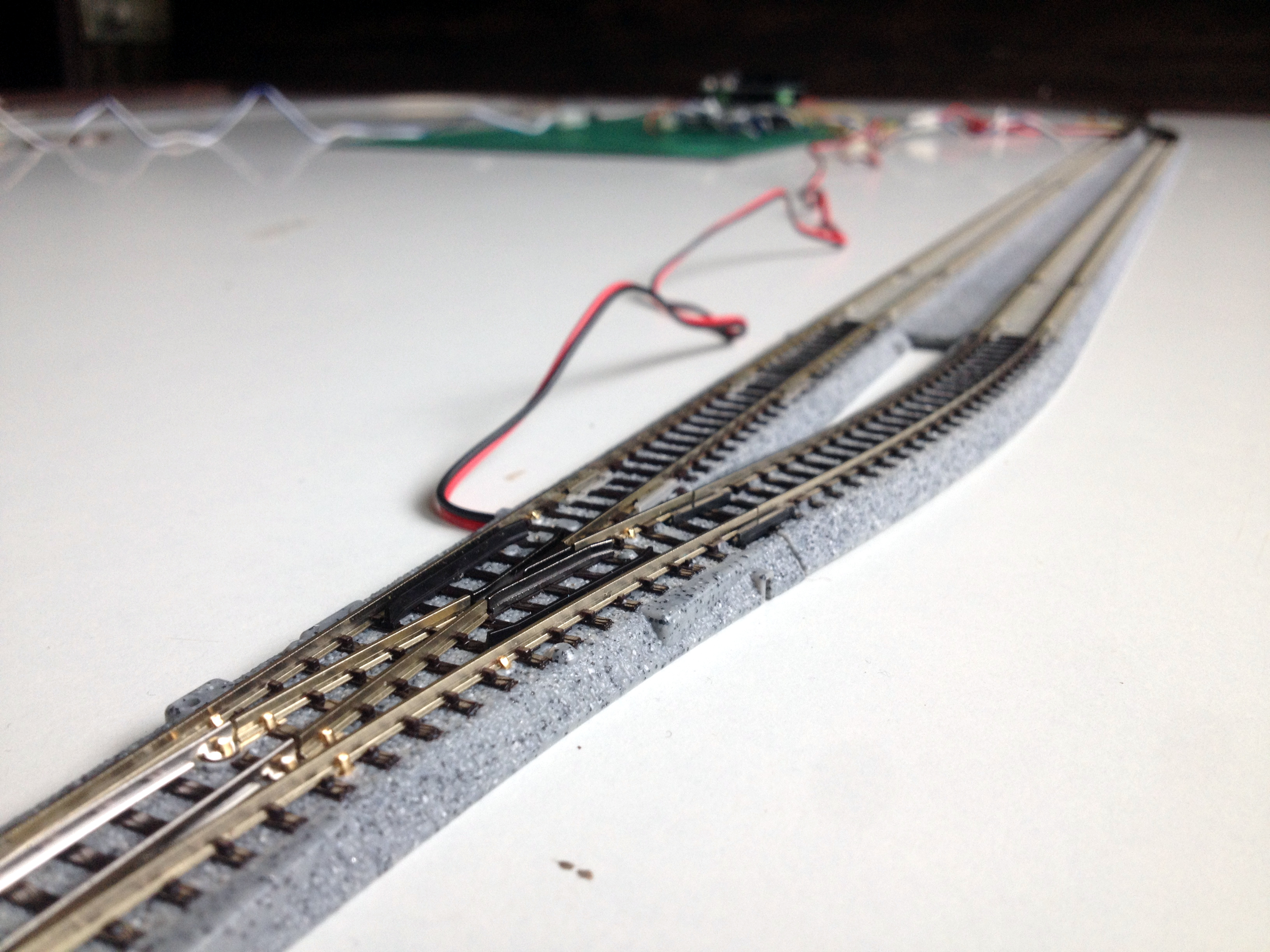
Make the Layout
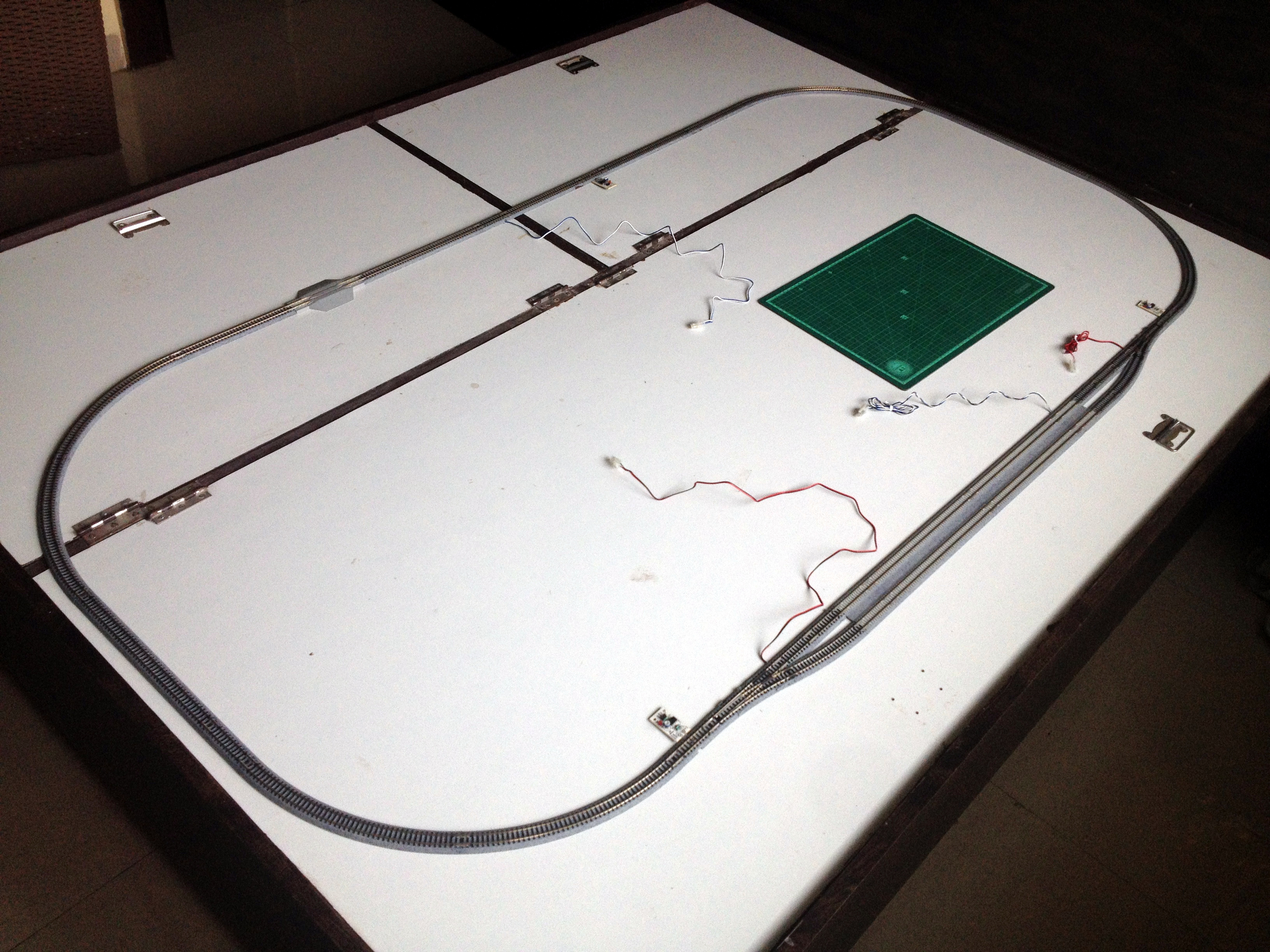
Click on the first image for more information.
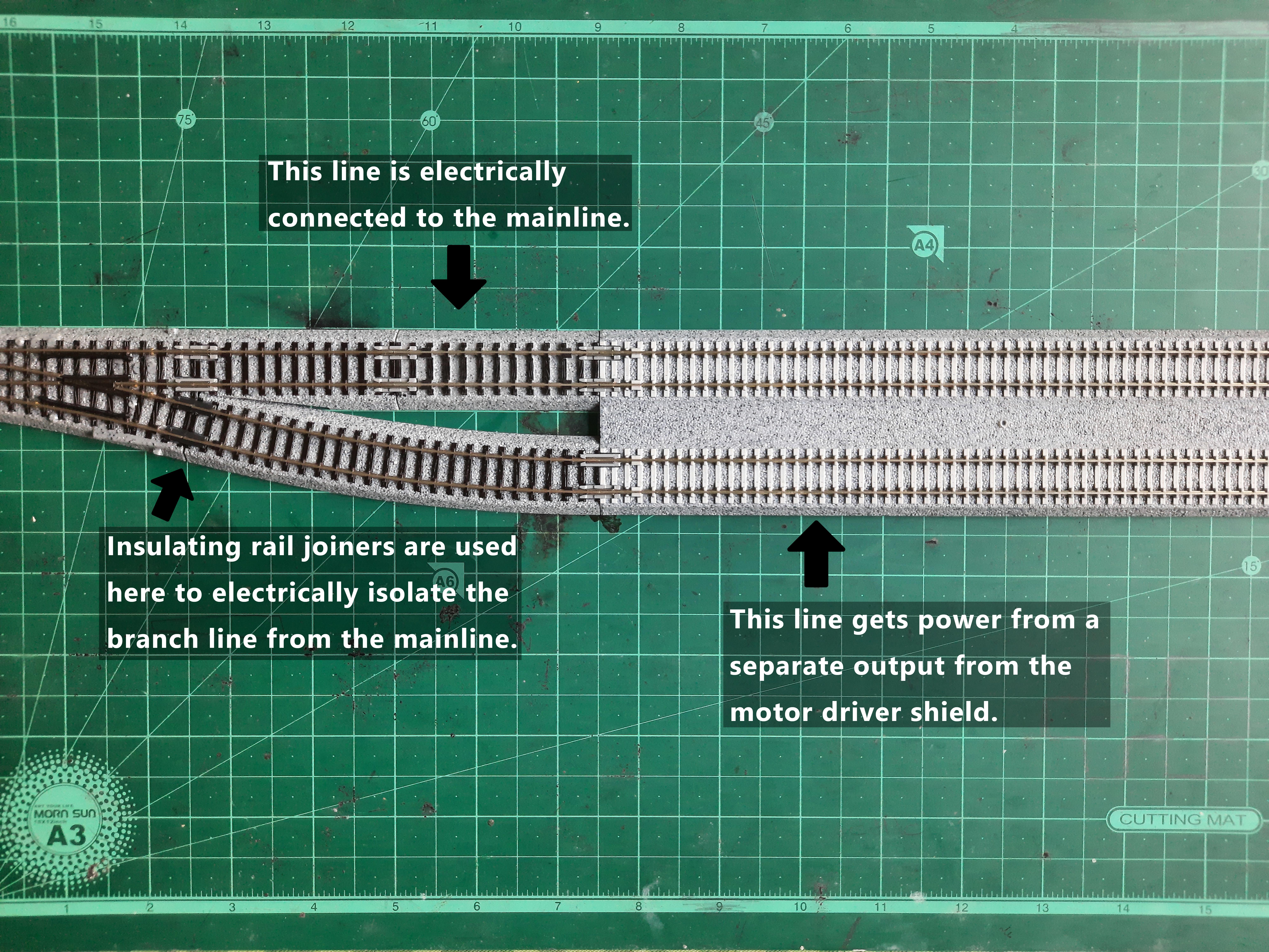
Make the layout and install a power feeder on the mainline as well as the passing siding. Make sure to isolate the passing siding tracks electrically from the mainline using insulated rail joiners at the branching location of the siding track near both the turnouts.
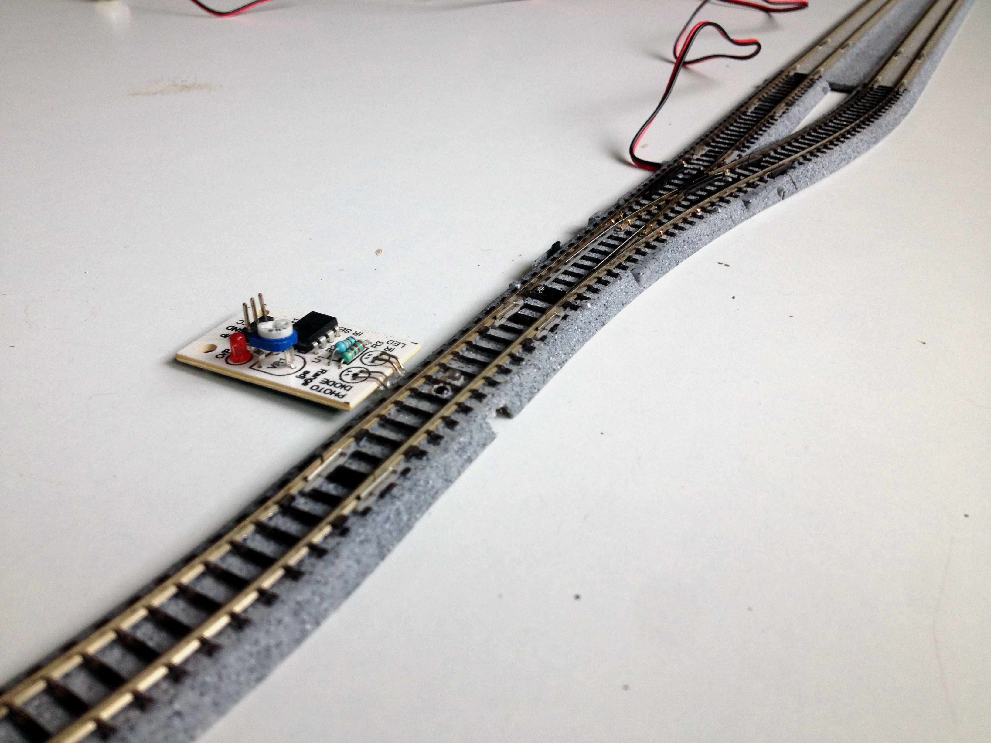
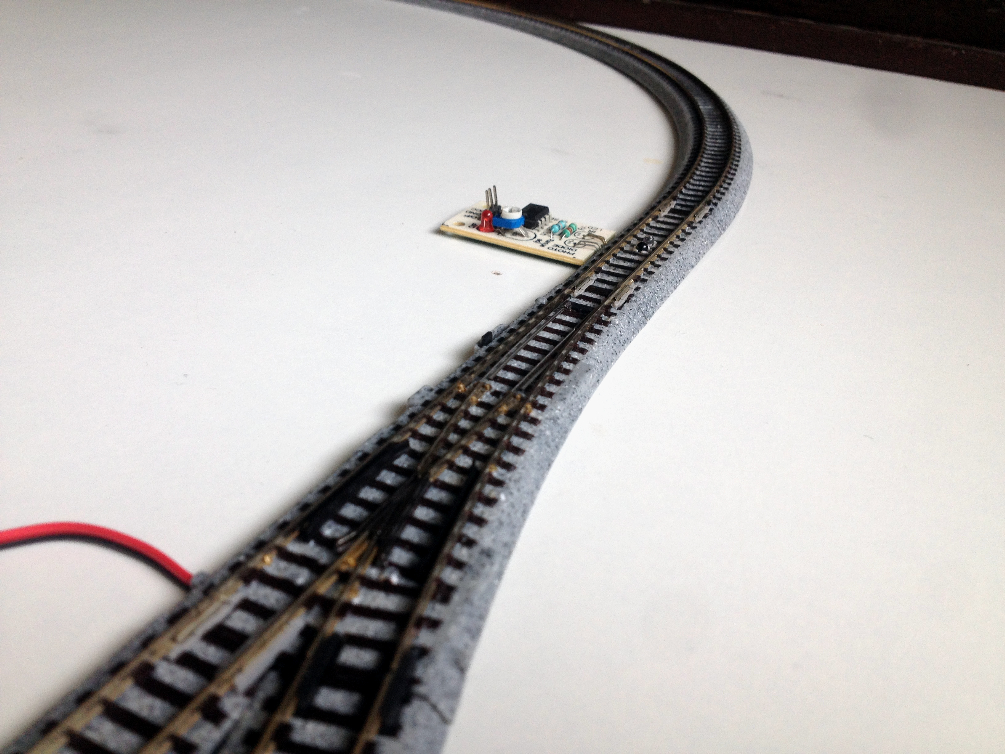
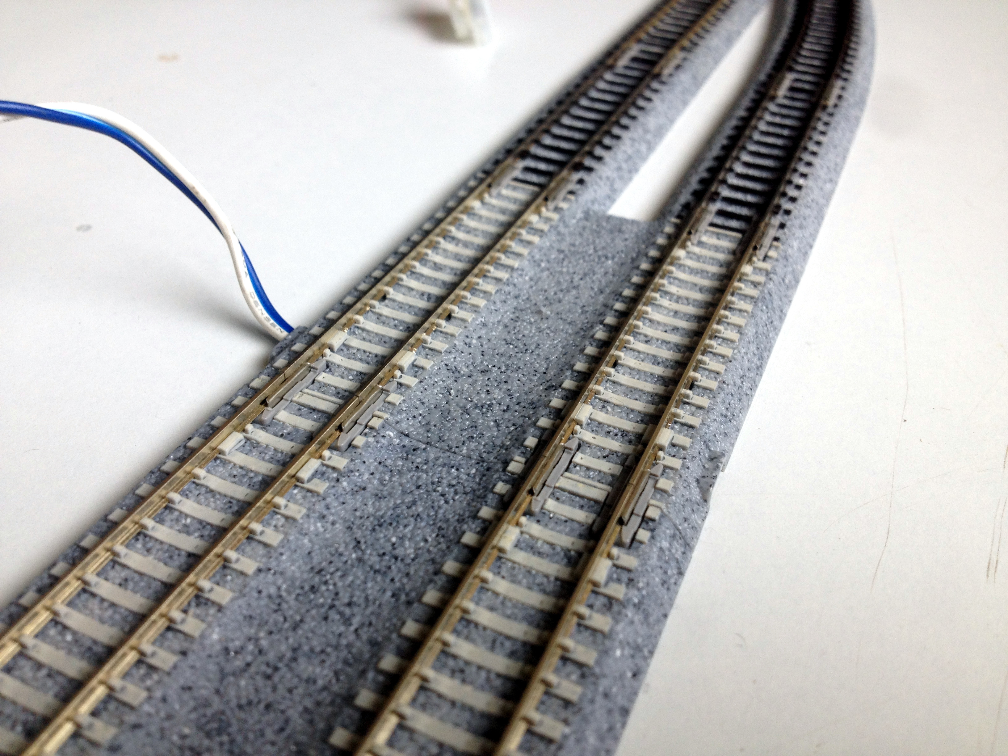
Note the location of each 'sensored' track:
- The first 'sensored' track is installed just after the turnout installed at the exit of the siding so that the train leaving the siding crosses it just before coming on the mainline.
- The second 'sensored' track is installed in the mainline some distance before the entrance of the siding(See the first image for reference).
- The third 'sensored' track is installed just before the turnout installed at the entrance of the siding.
Install the Motor Driver Shield on the Arduino Board
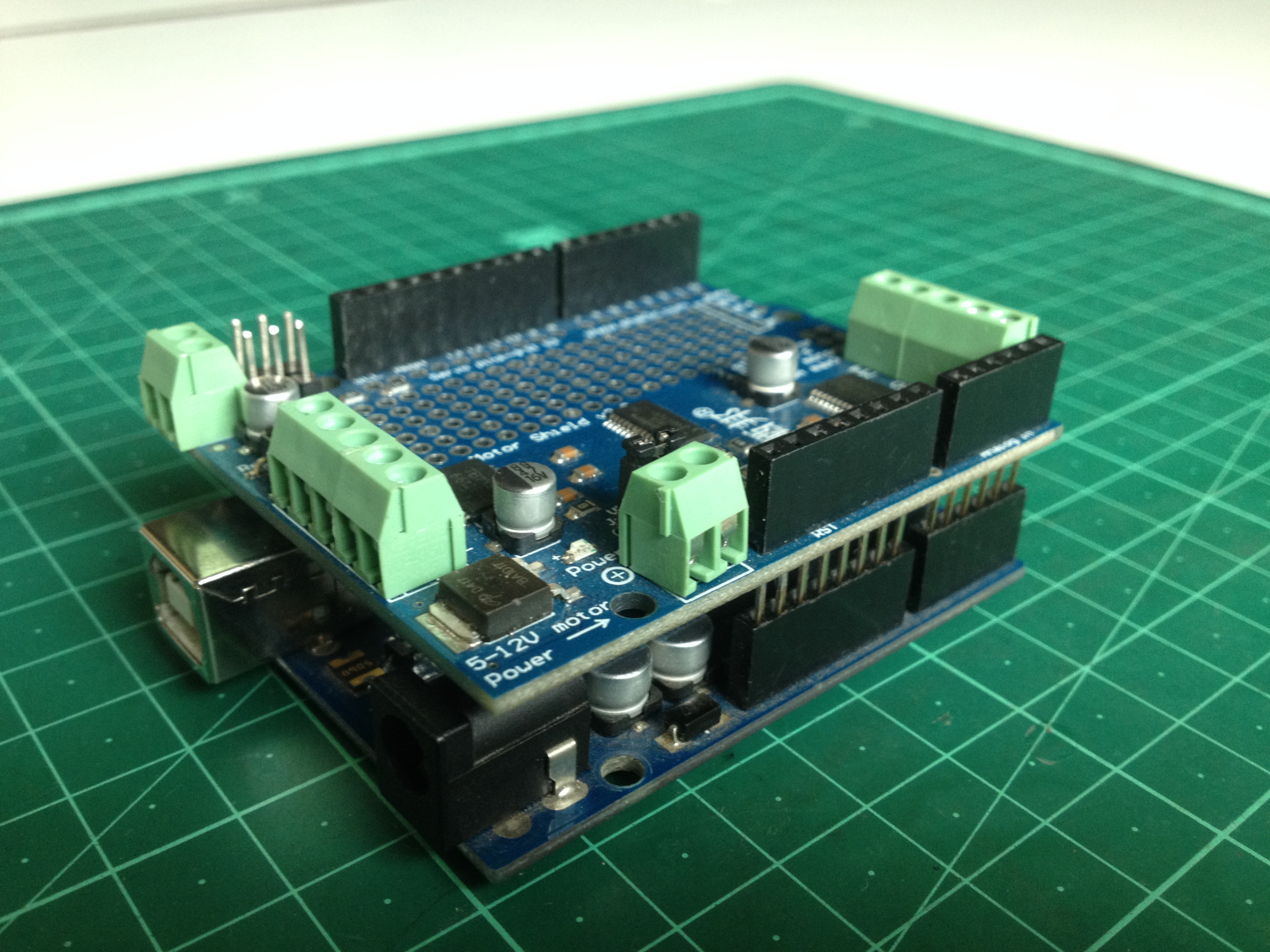
Install the motor driver shield on the Arduino board by carefully aligning the pins of the driver board with the female headers of the Arduino board. Take extra care to ensure the pins do not get bent in the installation process.
Connect the Track Power Wires to the Motor Driver Shield
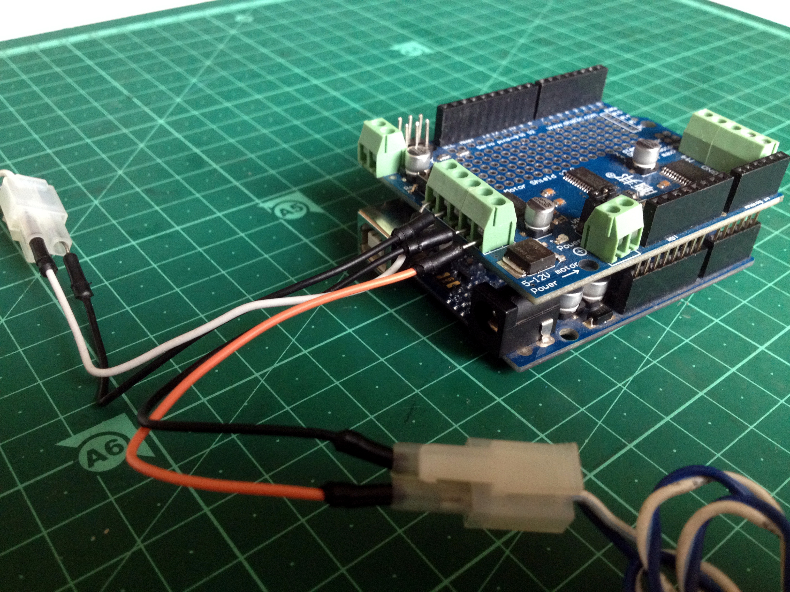
Make the following track power connections:
- Connect the mainline track's power feeder to the terminal block on the shield marked 'M1'.
- Connect the passing siding track's power to the terminal block on the shield marked 'M2'.
Connect the Turnouts to the Motor Driver Shield
Connect the turnouts in parallel by connecting their +ve(red) and -ve(black) wires together and connect them to the terminal block on the motor shield marked 'M3'.
Install the Expansion Shield on the Motor Shield
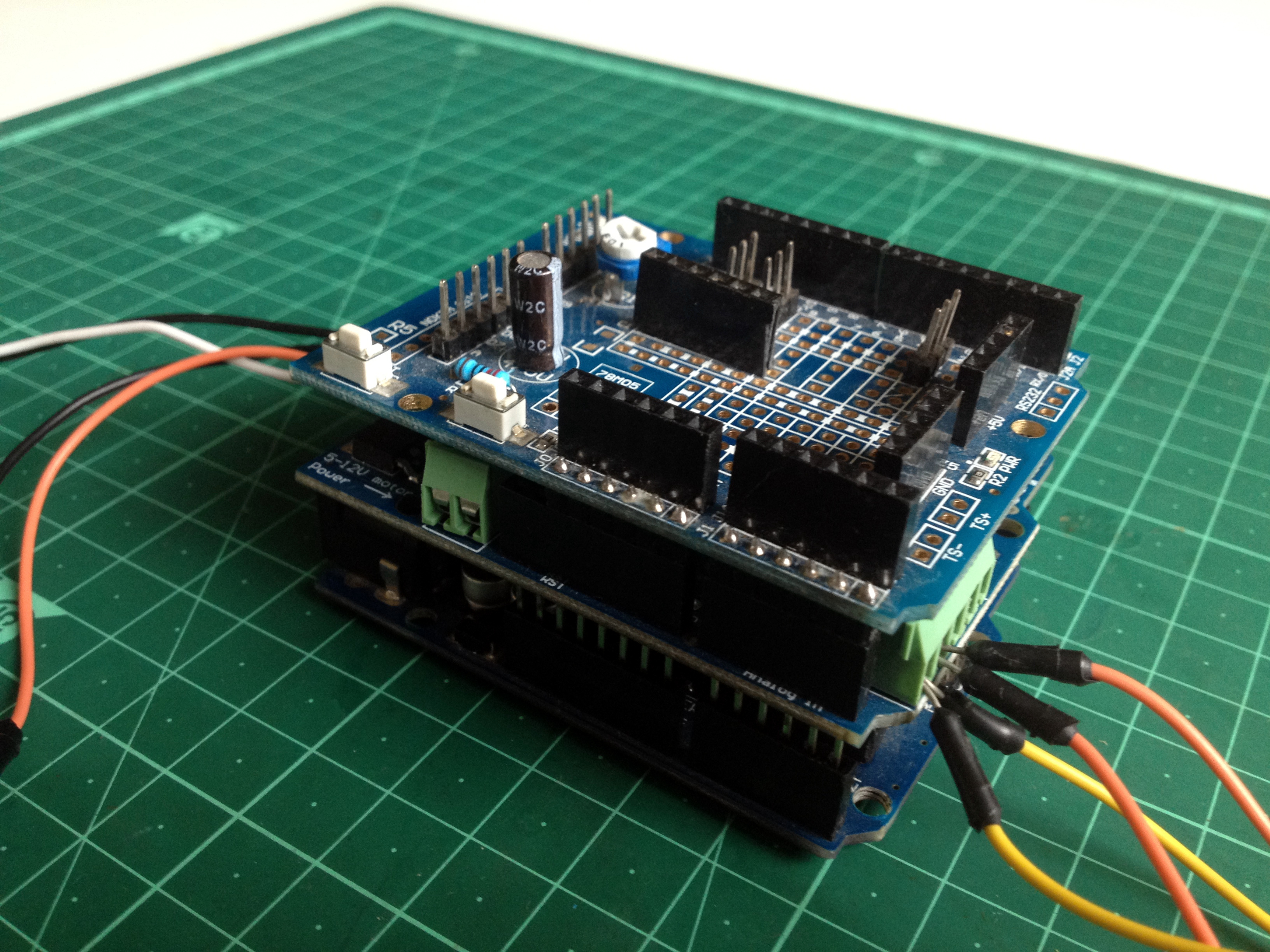
Install the expansion shield on the motor driver shield the same way the motor shield was installed on the Arduino board.
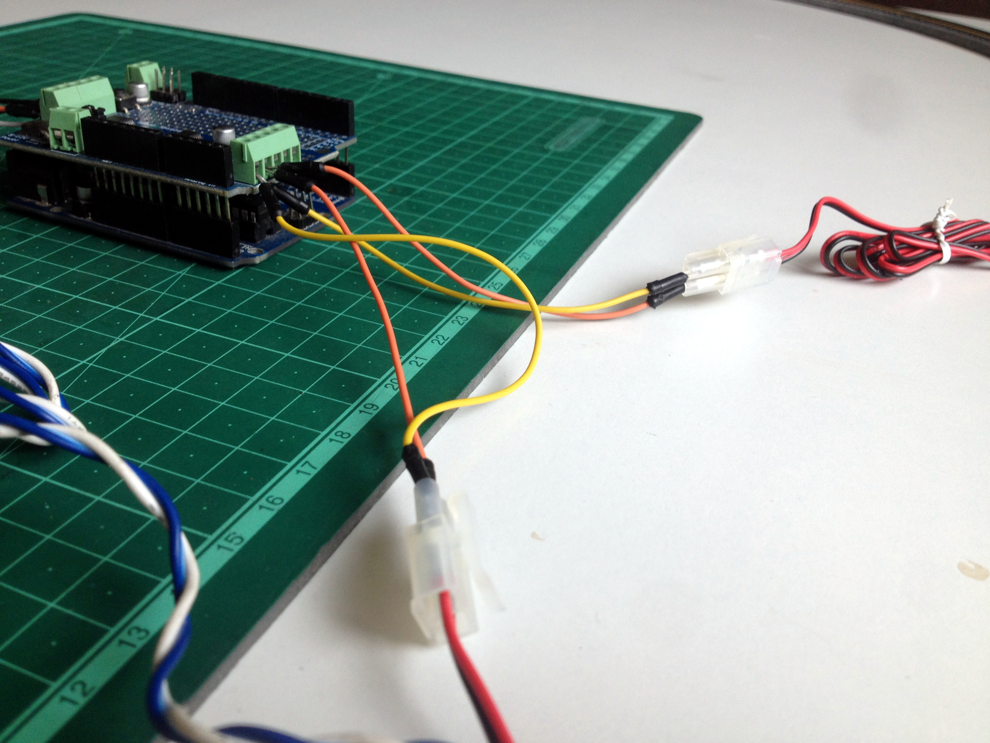
Connect the 'sensored' Tracks to the Expansion Shield
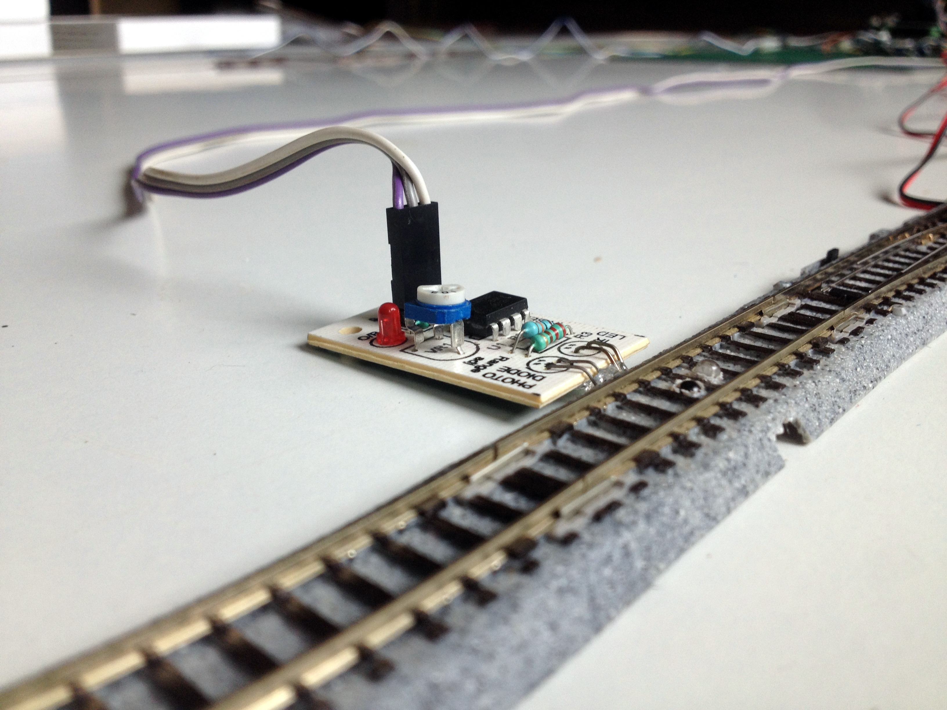
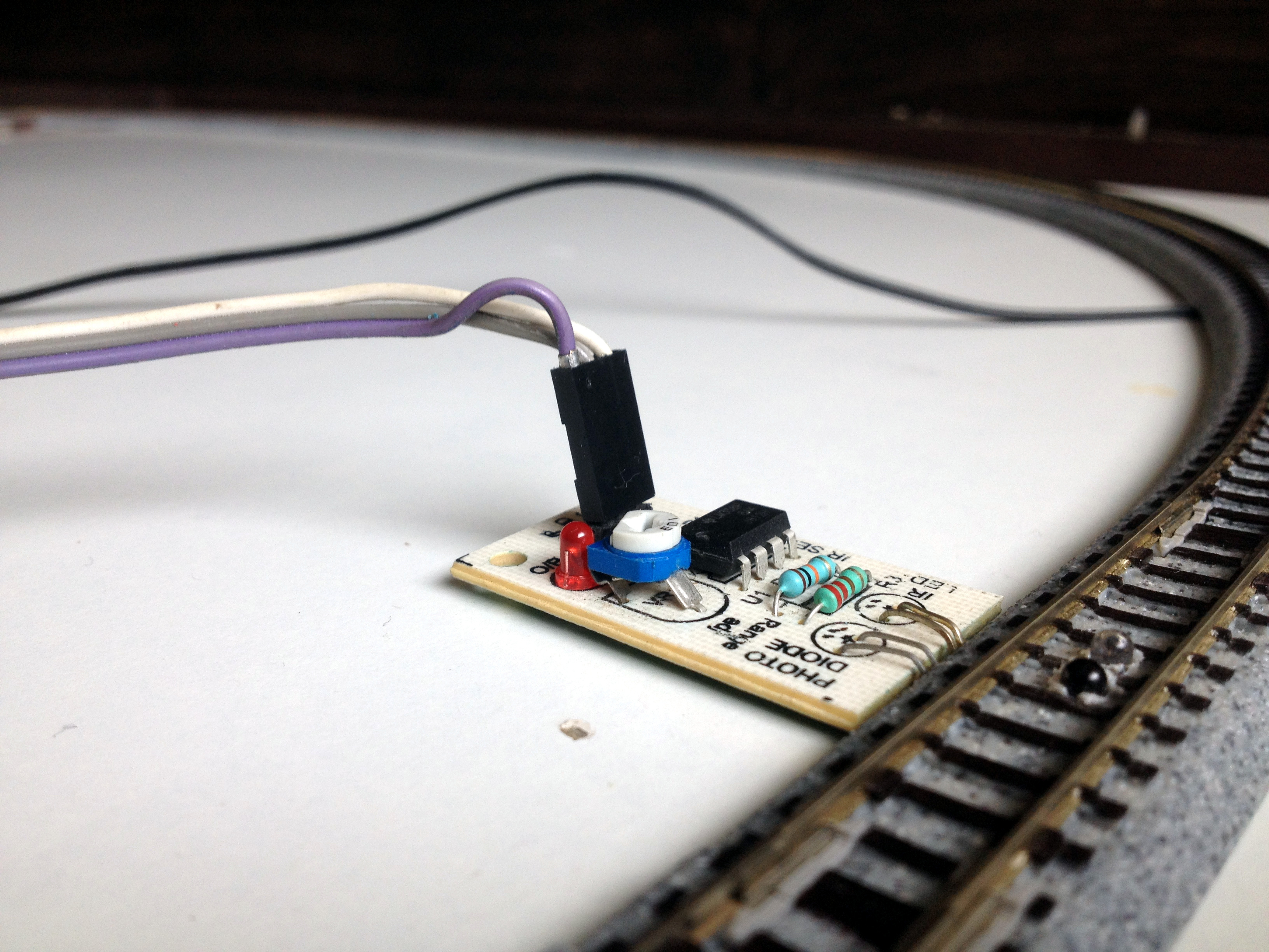
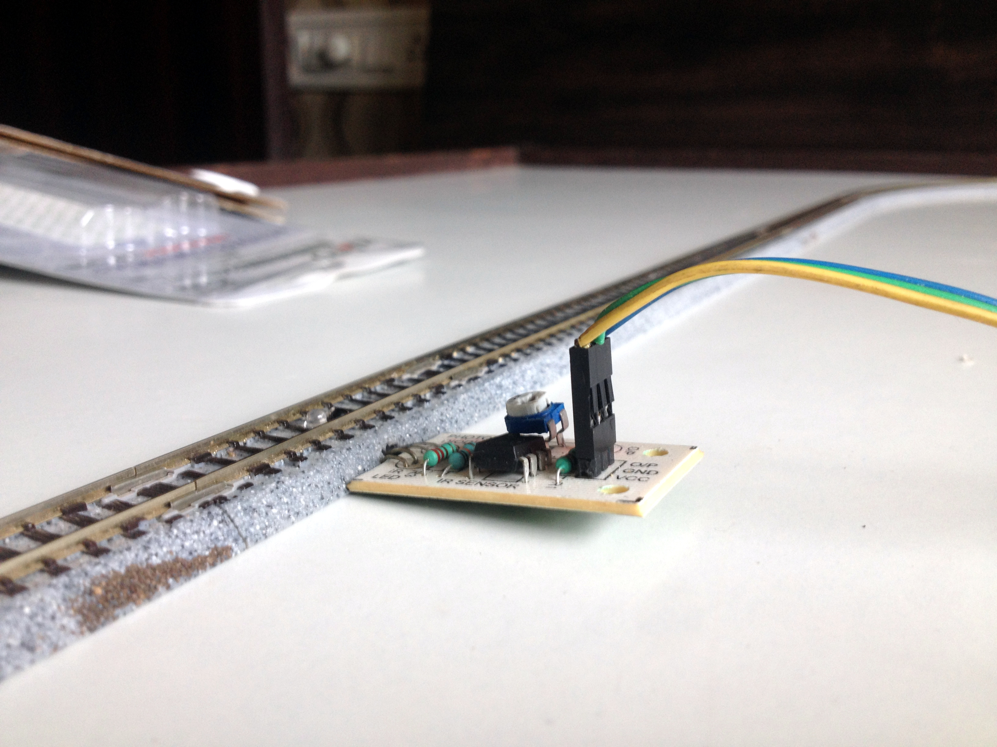
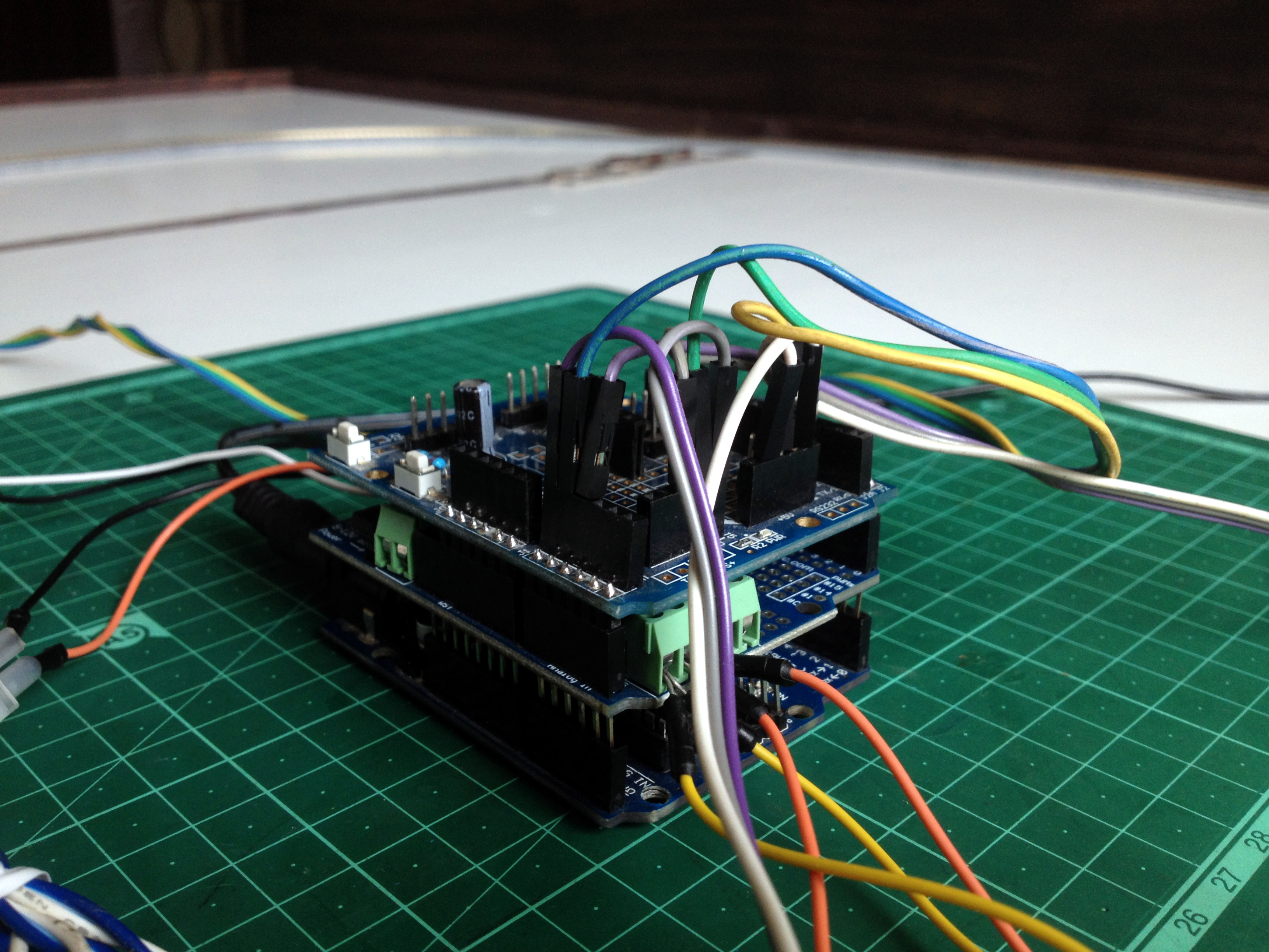
Connect each 'sensored' track's power to +5-volt header on the expansion shield and the 'GND' pin of each sensor to the 'GND' header of the shield. Next, make the following connections:
- Connect the first sensor's output pin to the input pin 'A0' of the Arduino board.
- Connect the second sensor's output pin to the input pin 'A1' of the Arduino board.
- Connect the third sensor's output pin to the input pin 'A2' of the Arduino board.
Place the First Train in the Siding
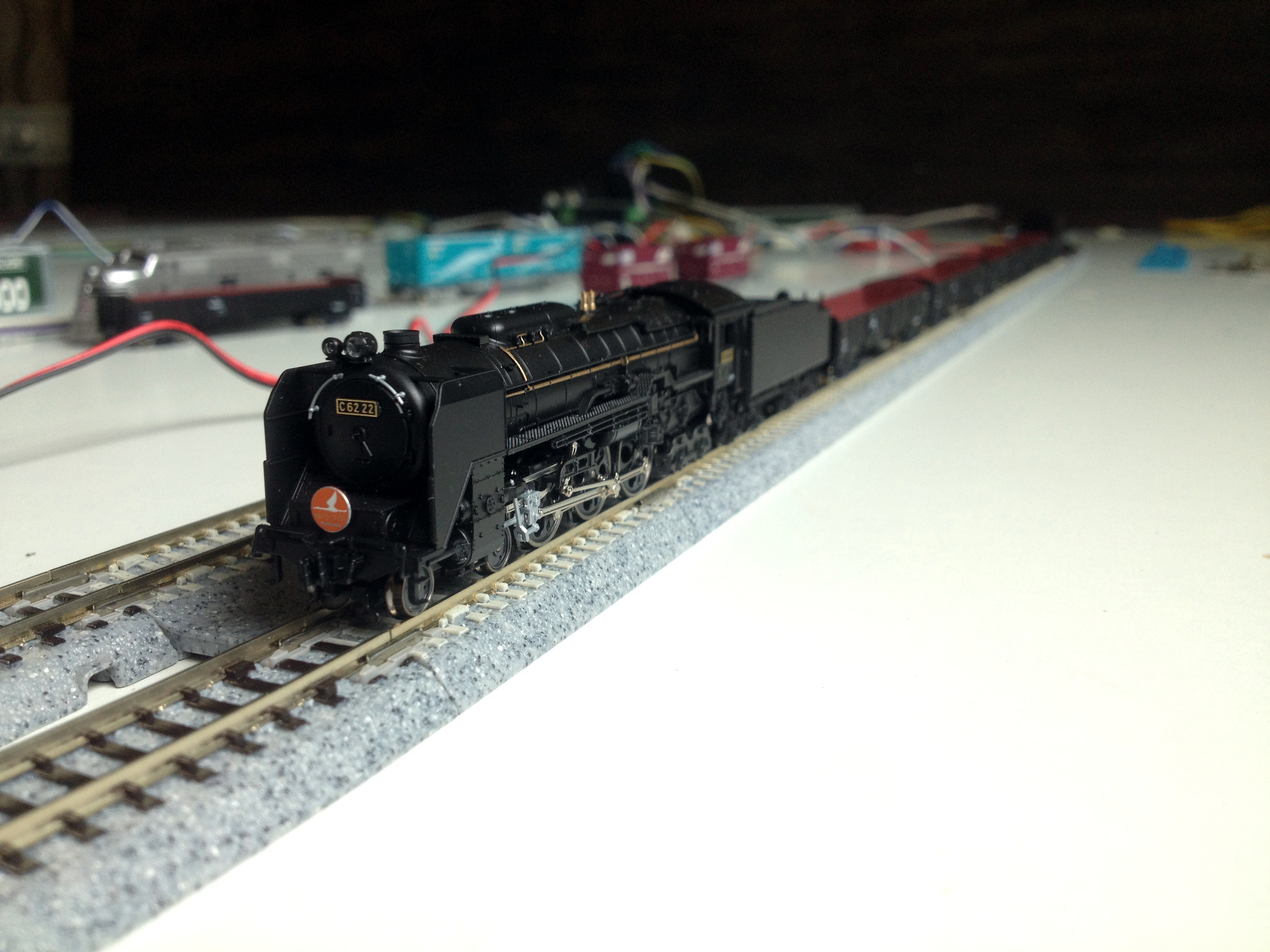
Place the first train in the siding, use of a rerailer tool is recommended, especially for steam locomotives.
Power Up the Setup

Connect the 12-volt power source to the Arduino board's power input connector and turn on the power.
Make Sure Everything Is Working Properly
After powerup of the system, the turnouts should switch to connect the siding track to the mainline. If anyone of them switches the wrong way, reverse the polarity of its connection with the motor shield.
After the turnouts have switched to the siding, the train should start to move slowly and accelerate after crossing the first 'sensored' track. If the train starts to move in the wrong direction in the siding or the mainline track, you know what to do.
Place the Second Train in the Siding Track
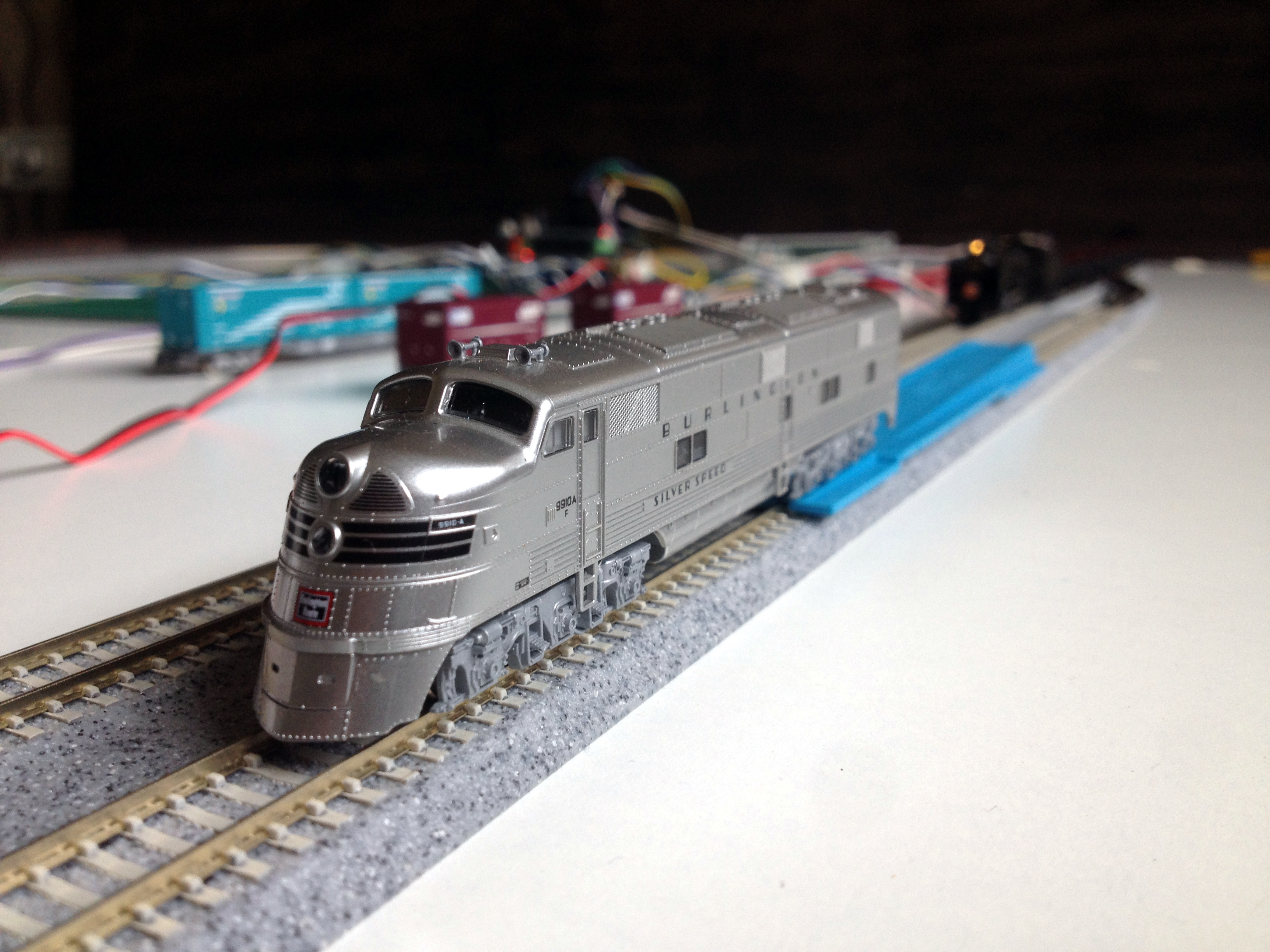
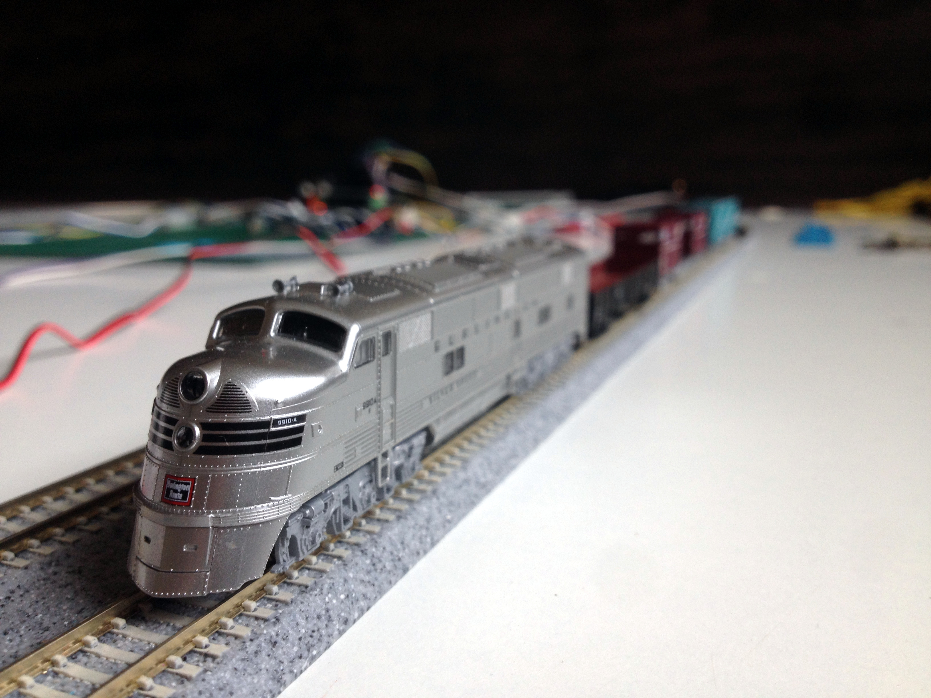
After the first train crosses the second 'sensored' track, the turnouts will switch away from the siding and the power of the siding track will be shut down. This is the time to place the second train in the siding.
Sit Back, Relax, and Watch Your Trains Running
Go Furthur!
Why not upgrade this setup? Try making the layout more complex, add more trains, turnouts, there is a lot to do!
Whatever you do, try sharing your creation with the community to let others see your work. All the best!