Automated LED Lighting for Planted Aquarium Using RTC
by indoorgeek in Circuits > Arduino
6476 Views, 20 Favorites, 0 Comments
Automated LED Lighting for Planted Aquarium Using RTC
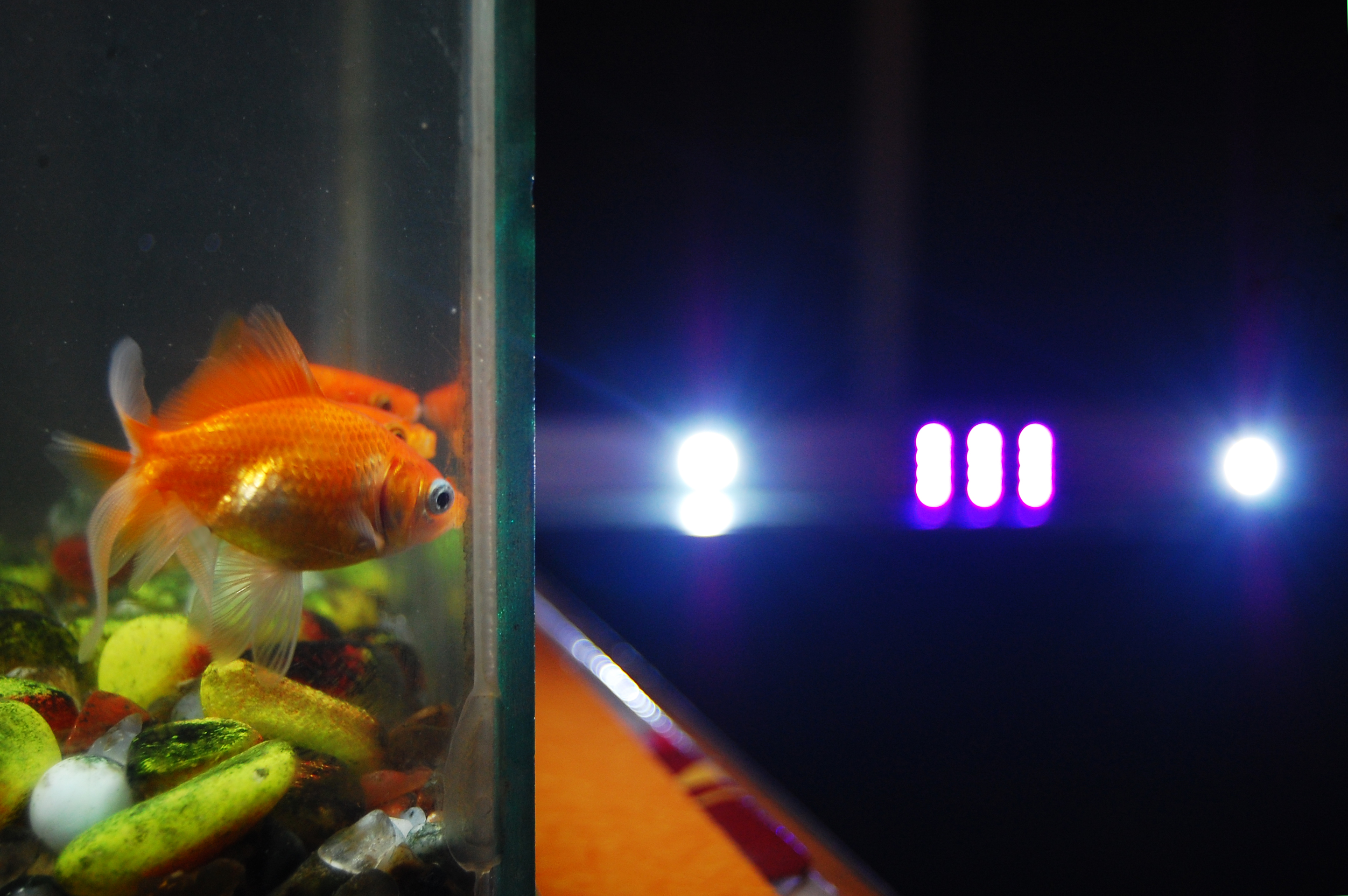
A couple of years ago I decided to set up a planted aquarium. I was fascinated by the beauty of those aquariums. I did everything which I was supposed to do while setting up the aquarium but neglected one most important thing. That thing was lighting. Everything looked fine for few days but then algae started growing everywhere in the tank and the plants were not doing great. It is a tough job to get everything back to normal.
Now after many years, I want to set up the aquarium again giving importance to lighting. I did some research on the internet and found that plants need continuous exposure to light for around 10-12 hours daily. I also came to know that plants respond more to the red and blue spectrum of light.
The trick is to simulate nature as closely as possible inside the aquarium. I could have manually switched ON or OFF the lights but why not automate it. This reduces the human error. So, I decided to make a LED lighting system which turns ON and OFF automatically using Arduino. This makes the lighting period consistent which is what the plants need.
My tank will be having a cover on top of it. So I decided to mount the controller board outside the tank as moisture is the biggest enemy of electronics.
Let's get started!
RTC - Real Time Clock
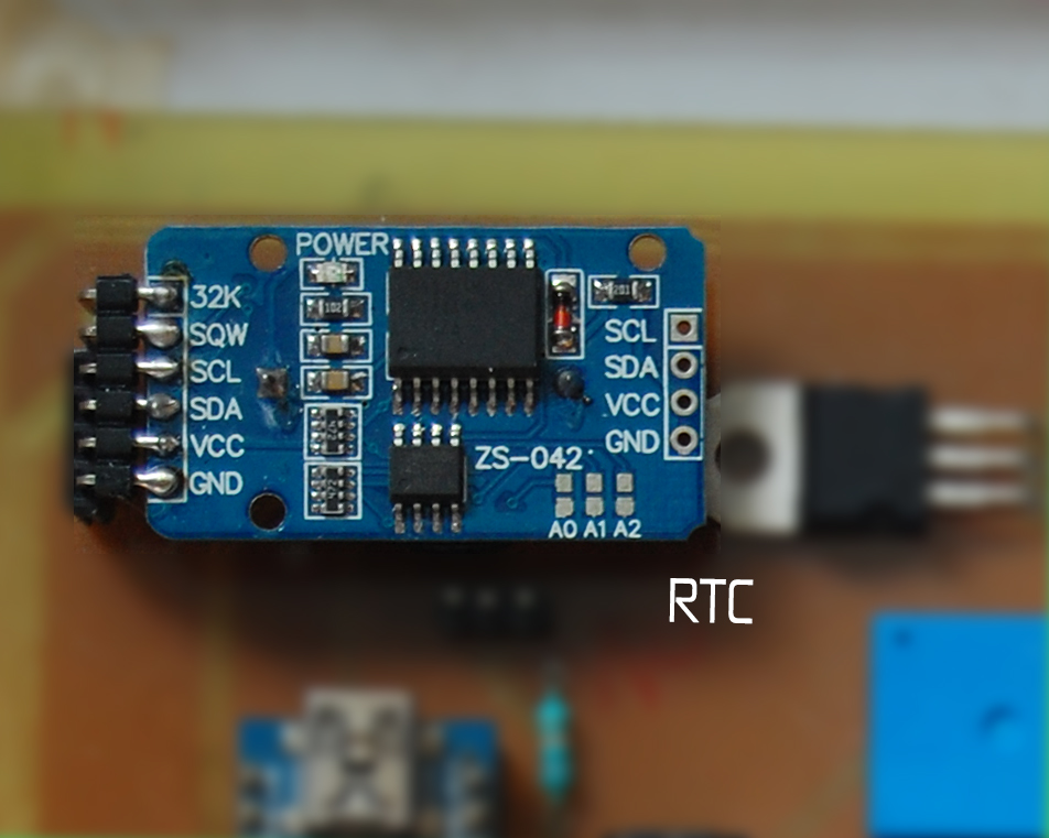
The plan is to turn ON and turn OFF the LEDs at a specific time of day. The LEDs won't turn ON to the full brightness immediately but instead, it will reach from zero brightness to full brightness in an hour. This is to simulate the sunrise. Same applies while turning OFF the LEDs.
The job of providing the exact time is done by the Real Time Clock or RTC. The advantage of using an RTC over millis() is that precise time can be obtained directly. Also, the RTC module has its own battery back up. So even if the Arduino is powered OFF or is reset the time is not lost. This makes it perfect for our application.
The module I will be using is DS3231 IIC Real Time Clock. It uses I2C interface to communicate with Arduino. I got mine from here.
Thanks to Rinky-Dinky Electronics for doing the hard work. Download the library for DS3231 here
LEDs and Drivers
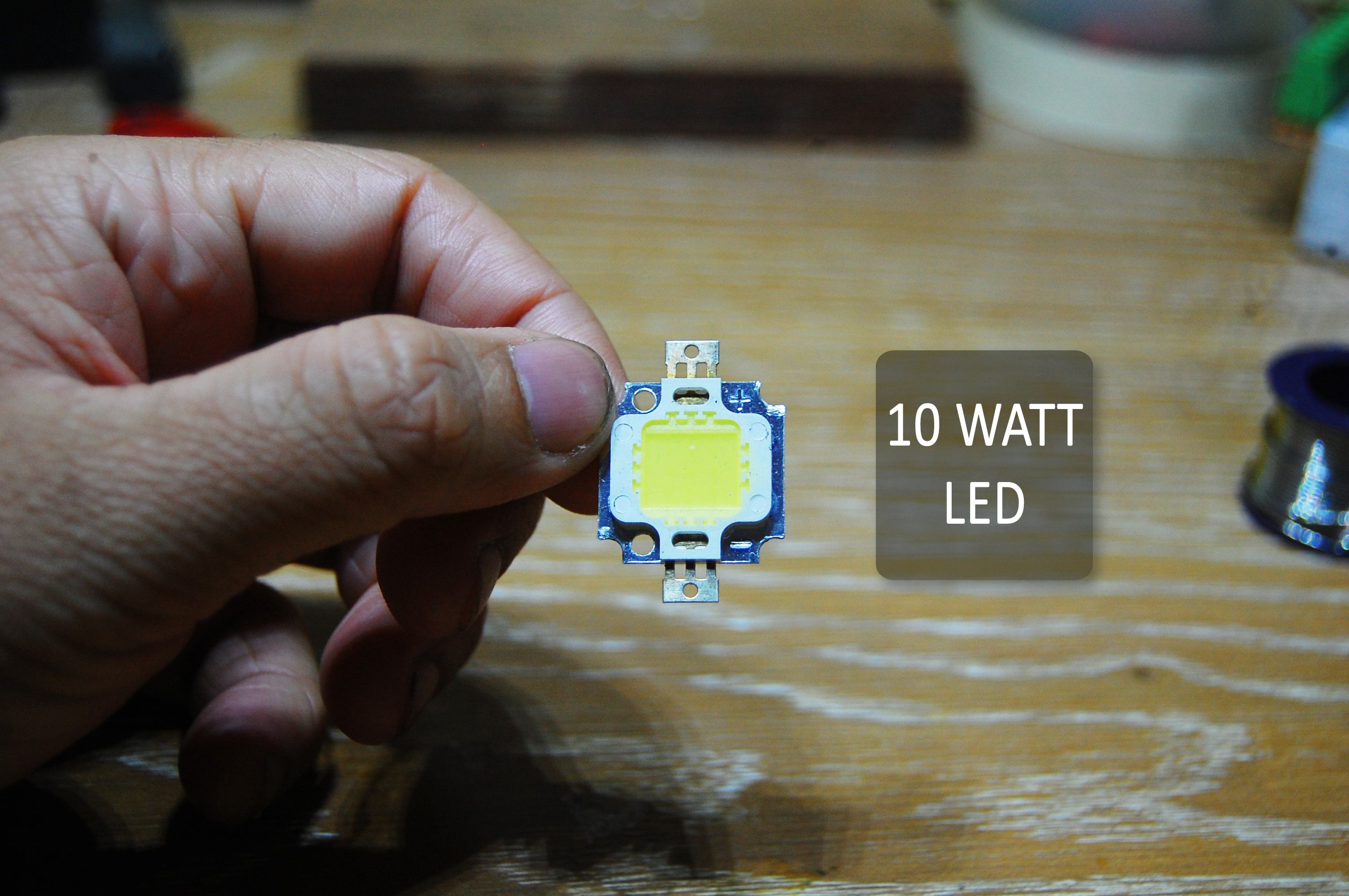
For a planted aquarium, the rule of thumb is 2 Watts per Gallon. Mine is a 20-gallon tank and I will be using two 10 Watt LEDs. I know that is half the recommended Watts but my tank sits just beside my window with plenty of light coming through it. I will test the setup for few weeks, monitor the plant growth and add more LEDs if needed.
I am using LEDs which I bought from Ebay with a color temperature of 6500K which is great for plant growth. According to the listing, the forward voltage should be 9-11V and maximum forward around 900mA. I ordered the LED drivers accordingly.
Why use drivers?
- We don't live in a perfect world. Hence, the output will be always less than the input. So where is the lost power? It is converted into heat. Same is the case with LEDs. A semiconductor has a Negative Temperature Coefficient (NTC) meaning that as the temperature increases its resistance decreases. A LED is a semiconductor too. As its temperature goes on increasing, its resistance starts decreasing due to which the current flowing through it increases. This increases the heating even more. This continues till the LED is damaged. Therefore, we need to limit the current so that it doesn't increase above a set limit. This job is done by the LED drivers.
On testing, I found that at 11V the LED is drawing about 350mA only. That's weird!
Setting up the LED Driver
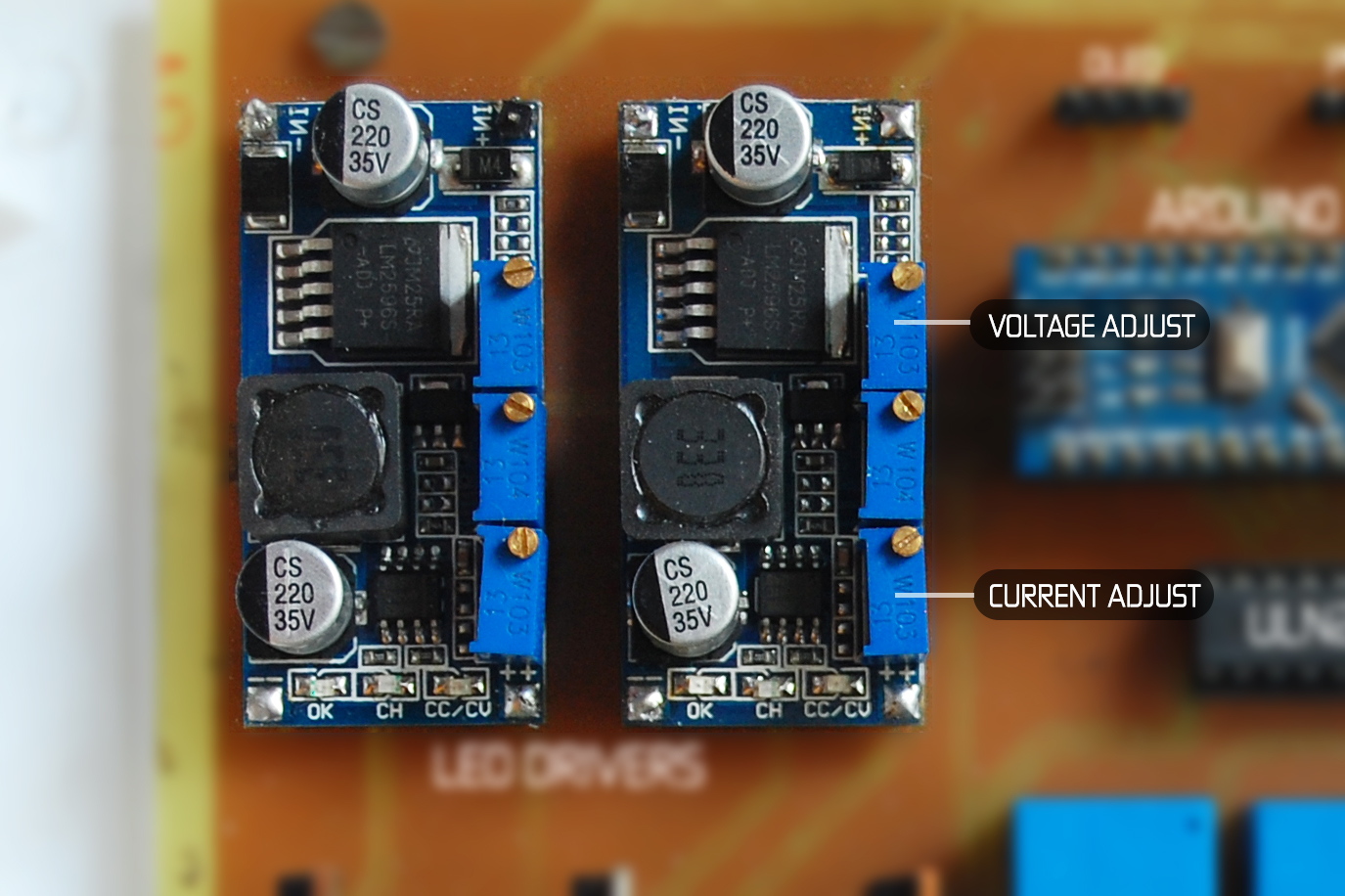
A driver is basically a device which provides a constant output voltage with a current limiting capability. There are various LED drivers available in the market which output a constant current. If you have bought the same one as I have bought, it will contain 3 pots for adjustments. We are concerned with only two of them. First one is for the voltage adjustment and the last one is used to set the current limit. Follow the steps to set it up:
- Connect 12V DC supply to the pins marked IN+ and IN-. Please check the polarity.
- Connect a multimeter to the pins marked OUT+ and OUT- and set the multimeter to read voltage.
- Turn the voltage adjust pot till the multimeter reads the rated forward voltage of LED. In my case, it is 9-11V. I chose 10.7V. (A bit less won't harm).
- Now put the multimeter in current reading mode. Current will start flowing through it. Turn the current adjust pot till the rated current of LED starts flowing.
- That's it! You can now connect your LED to it.
Making the LED Panel
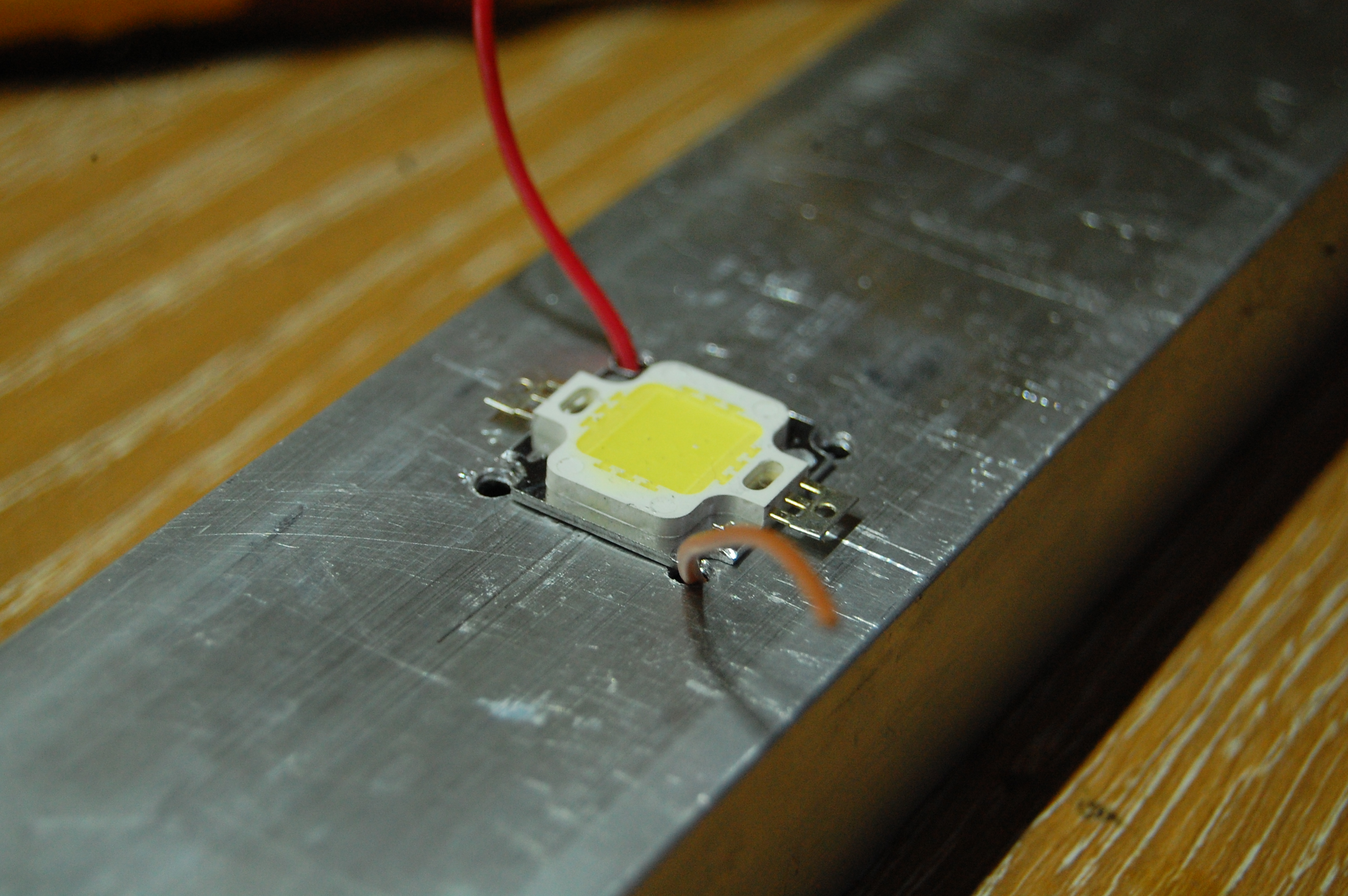
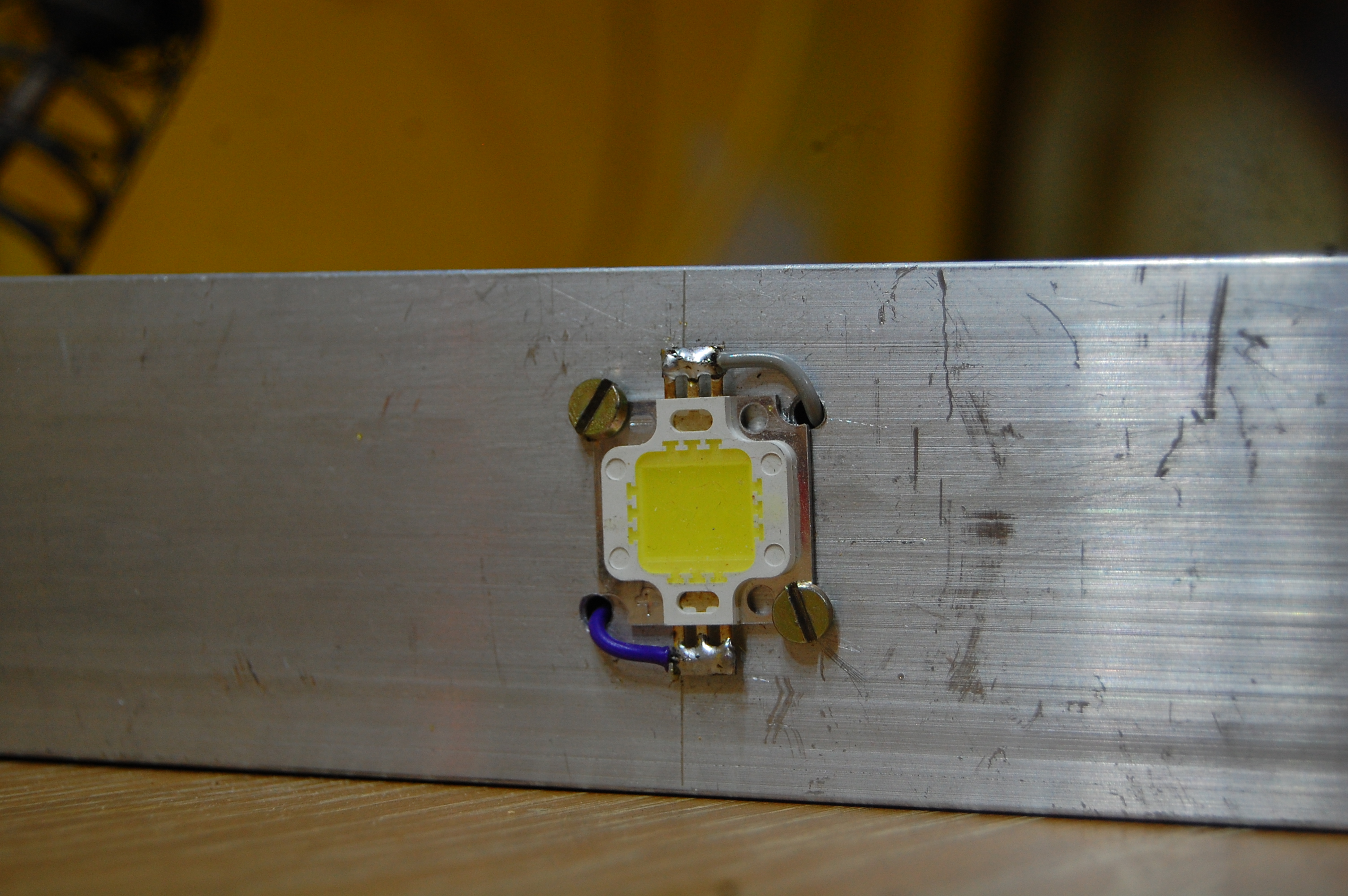
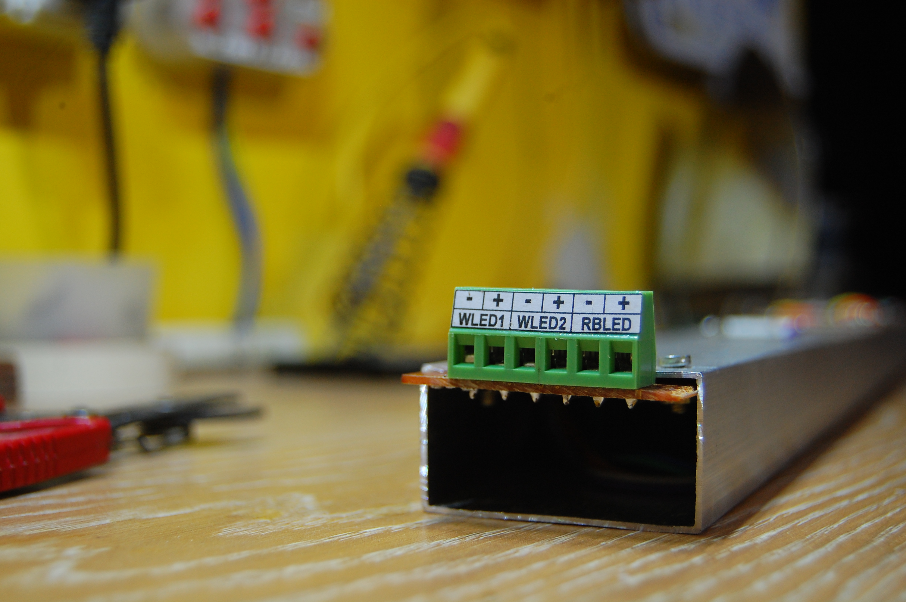
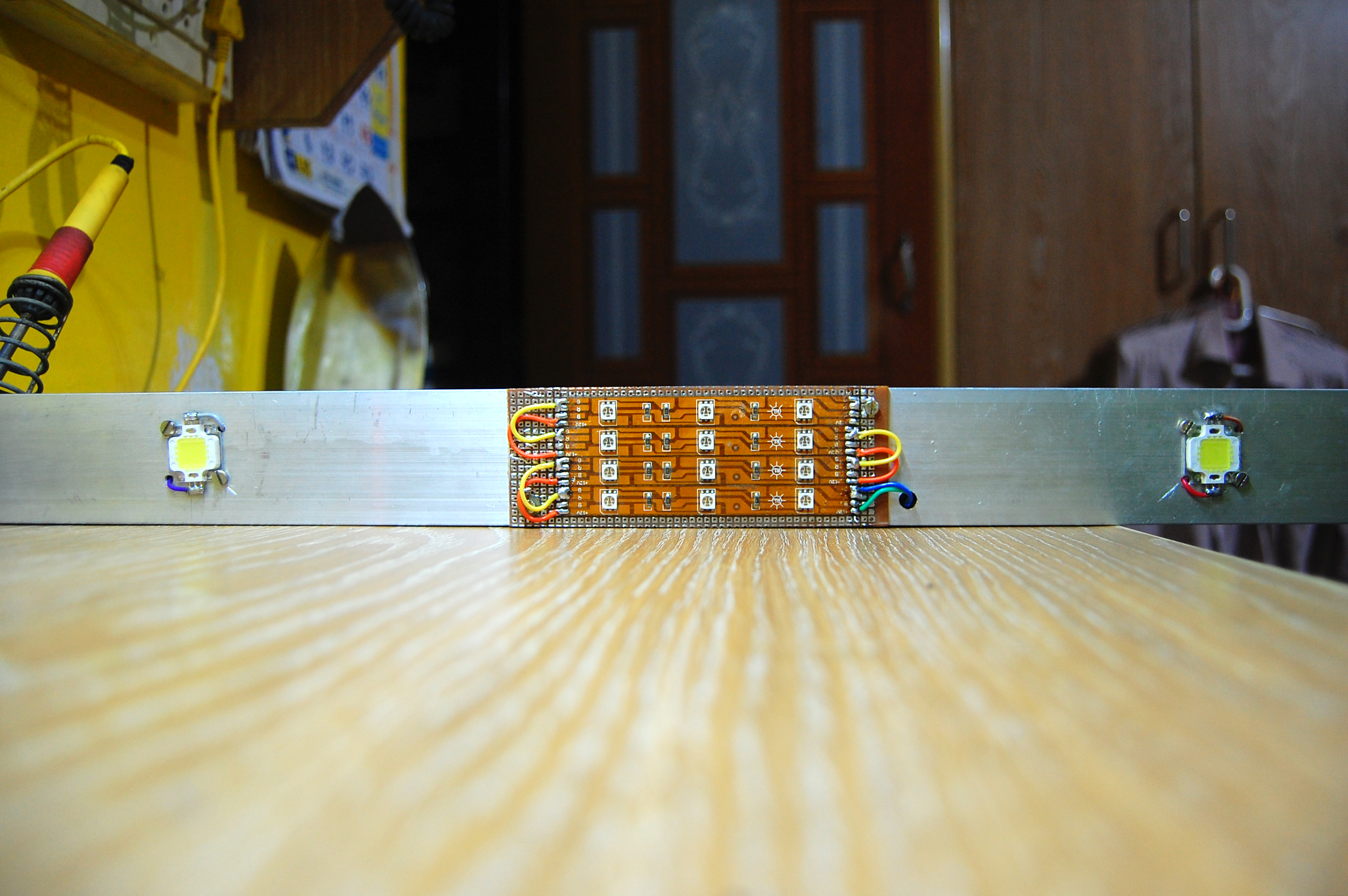
As mentioned earlier, I decided to use two 10 Watt LEDs and four RGB LED strips which I had laying around. I will be using the strip for red and blue colors. I used an aluminum frame (which is most commonly used to make window and door frames) almost the length of my aquarium. I went with an aluminum frame as it serves as a heatsink for the LEDs. Heatsinks are important for such high power LEDs as they dissipate a lot of heat. The lifespan of LED will reduce in the absence of it. As it is hollow in between, all the wiring can remain hidden and safe inside it.
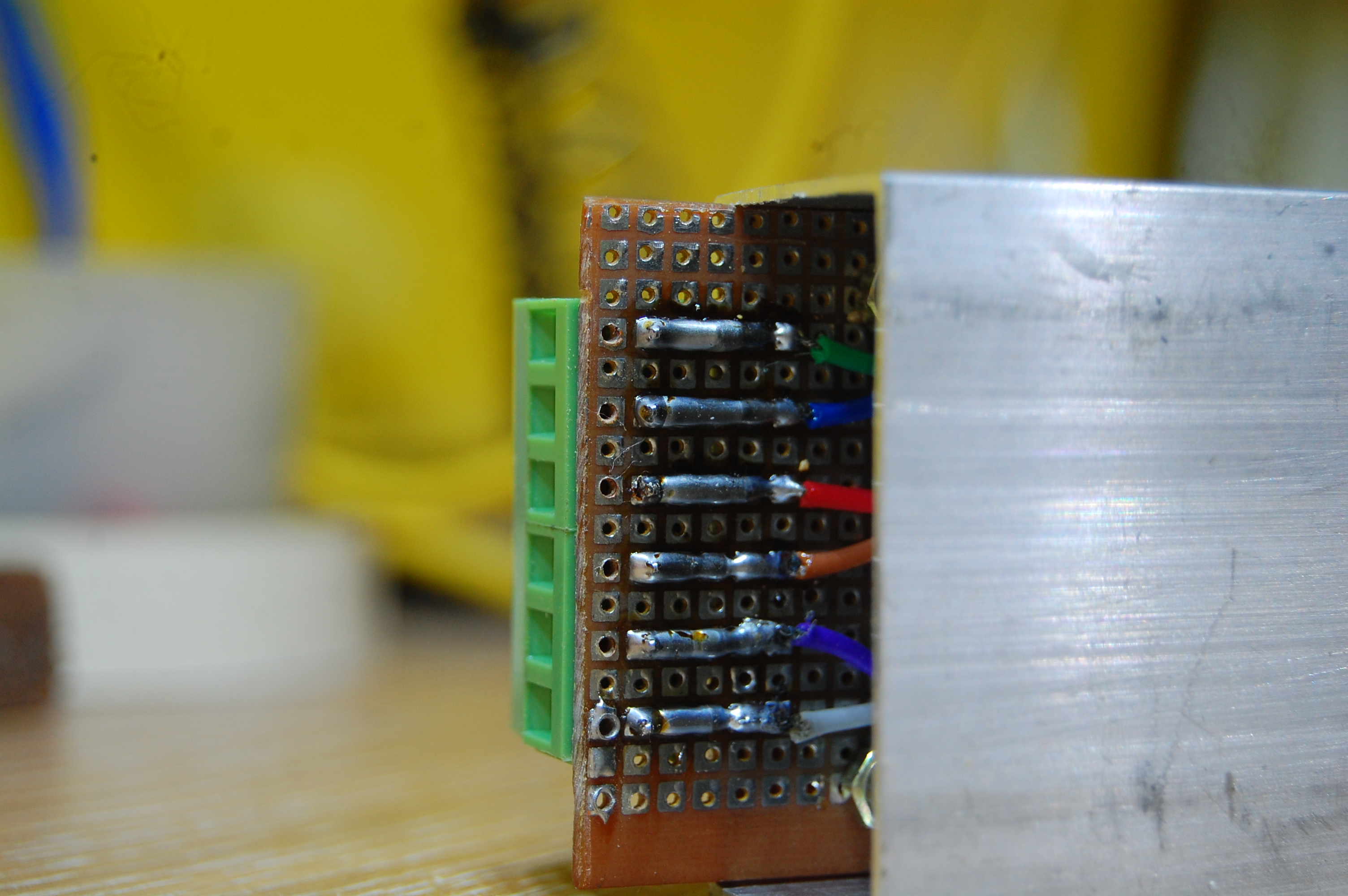
I extended all the LED connections to the 6 terminal connectors as shown in the picture. This becomes easy to connect the panel to the controller which we will be making next.
Making the Controller
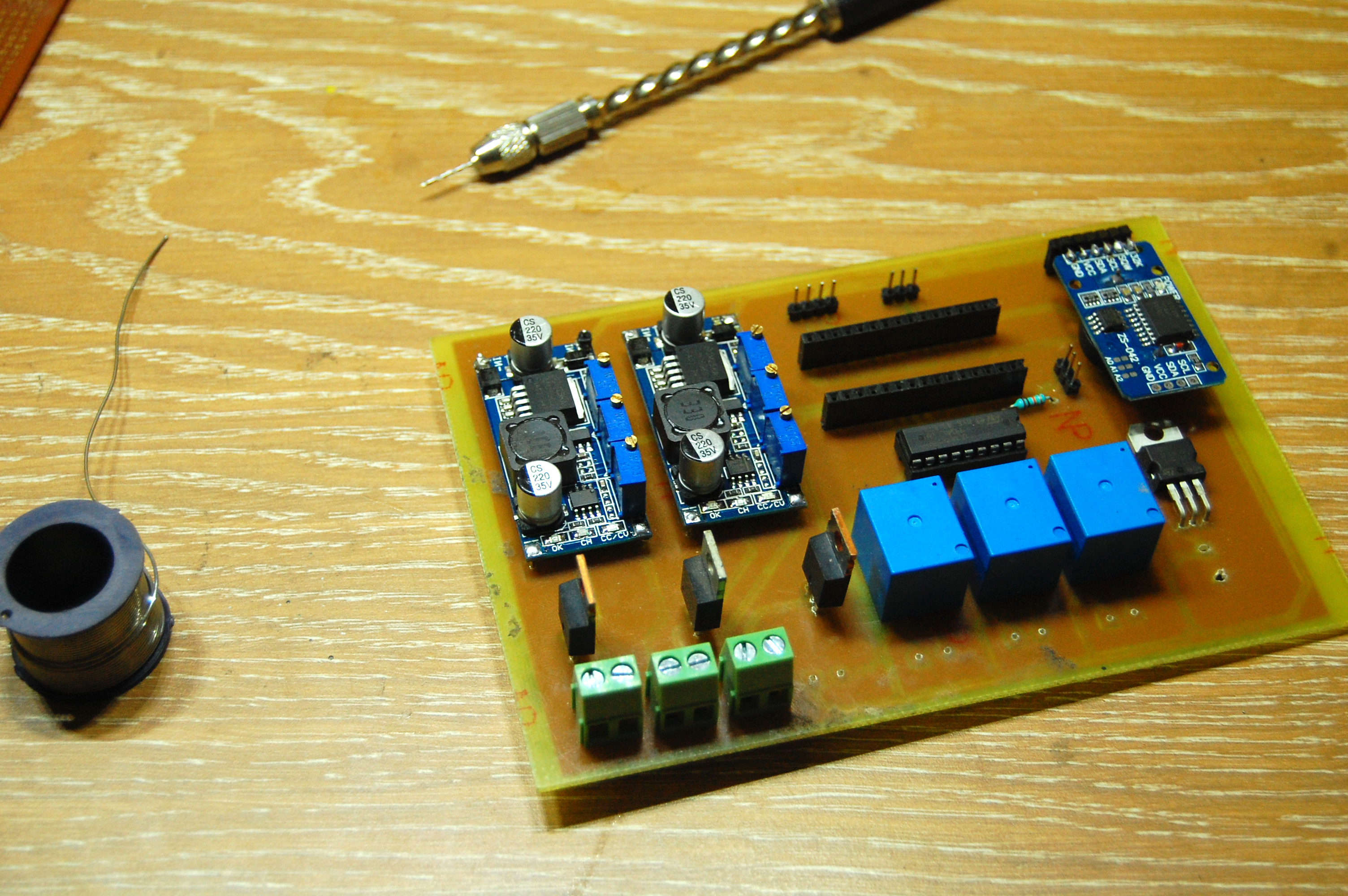
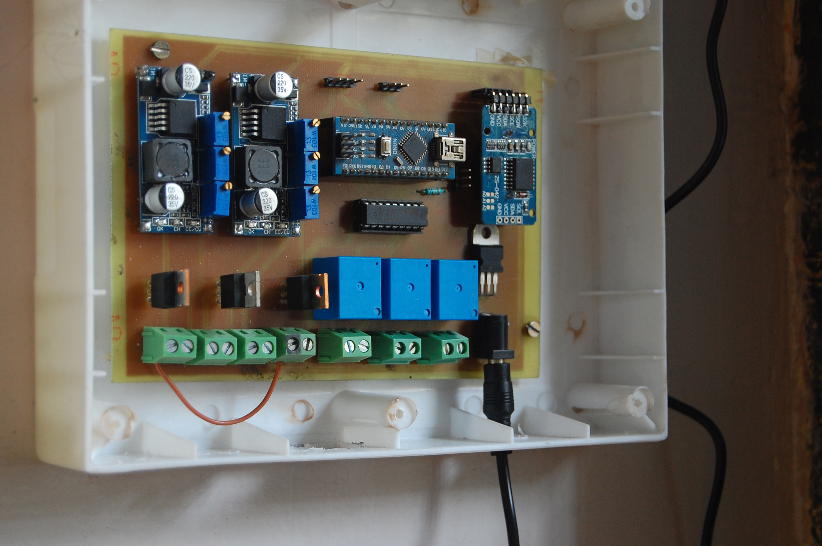
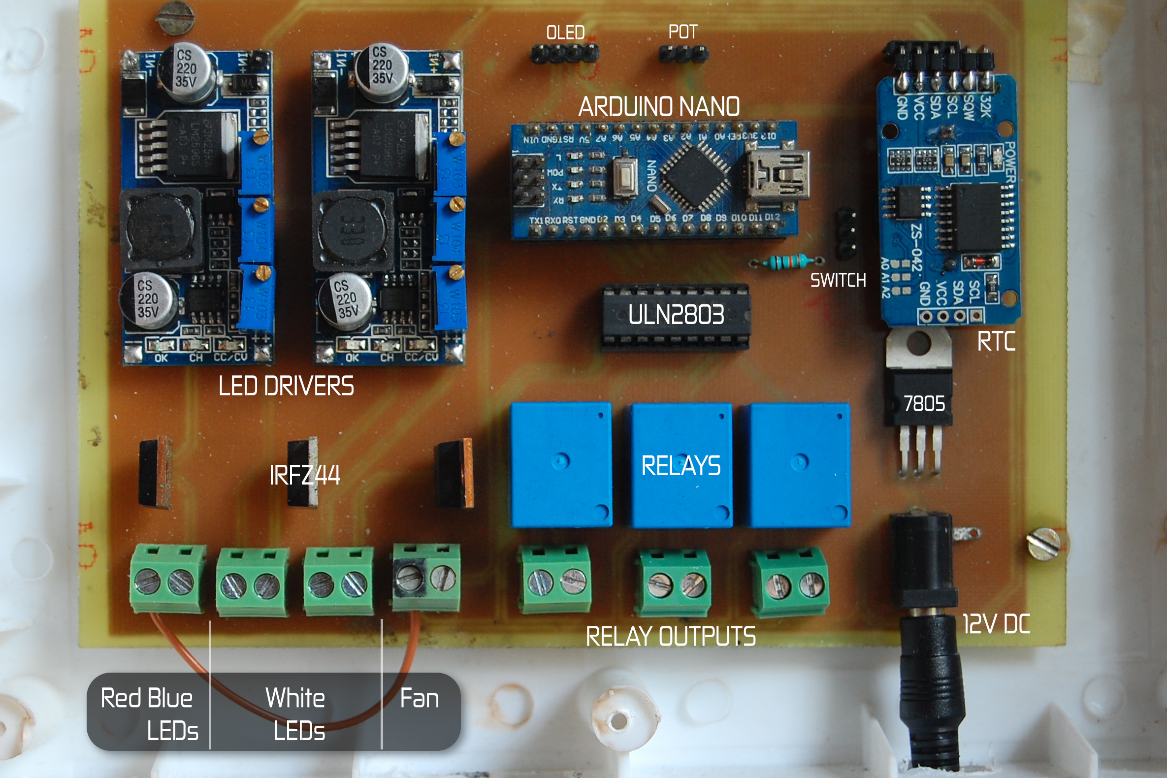
The main aim is to turn ON and turn OFF the LEDs according to the time set by the user. The brain of the controller is an Arduino Nano. Why just control the lighting? As I had some relays laying around, I will be using them to switch ON or OFF some of the appliances like the filter, air pump, heater, etc. too if needed. I added a 12V DC computer fan to provide ventilation.
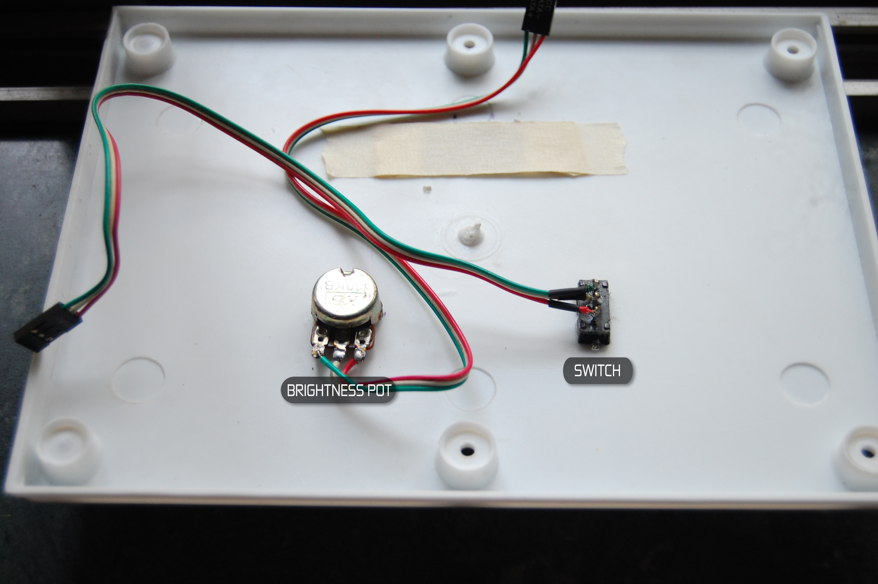
A switch is provided to choose between the Manual and Automatic mode. In case if we need to access the fish tank after the LEDs are turned OFF at night, the switch can be turned to Manual position and then the brightness of the LEDs can be controlled using a Pot.
I used a ULN2803 Darlington Transistor Array IC to control the relays and fan. This IC is commonly known as a Relay Driver.
The schematic for the build has been attached here. A custom PCB will make it look neat and professional.
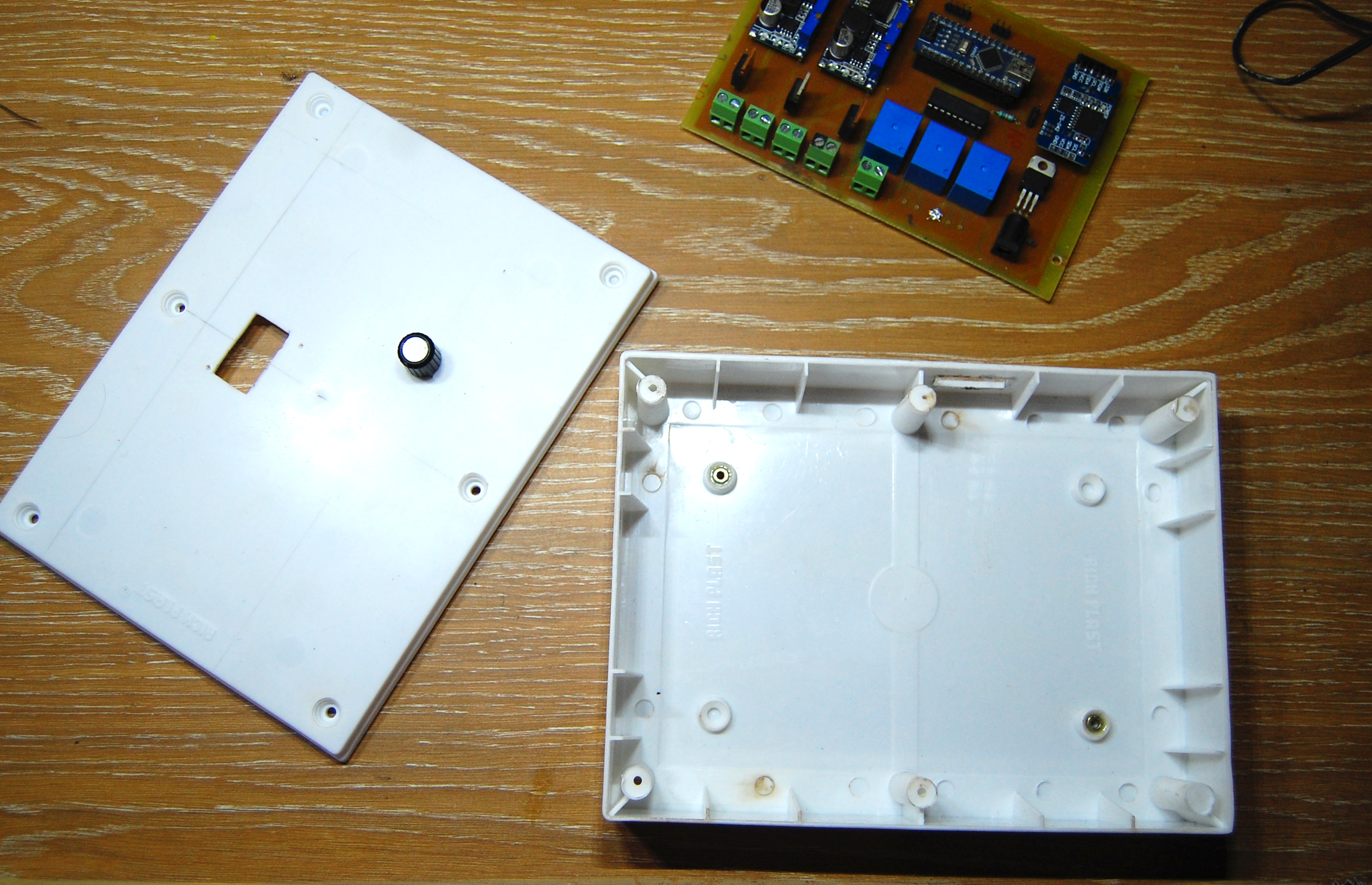
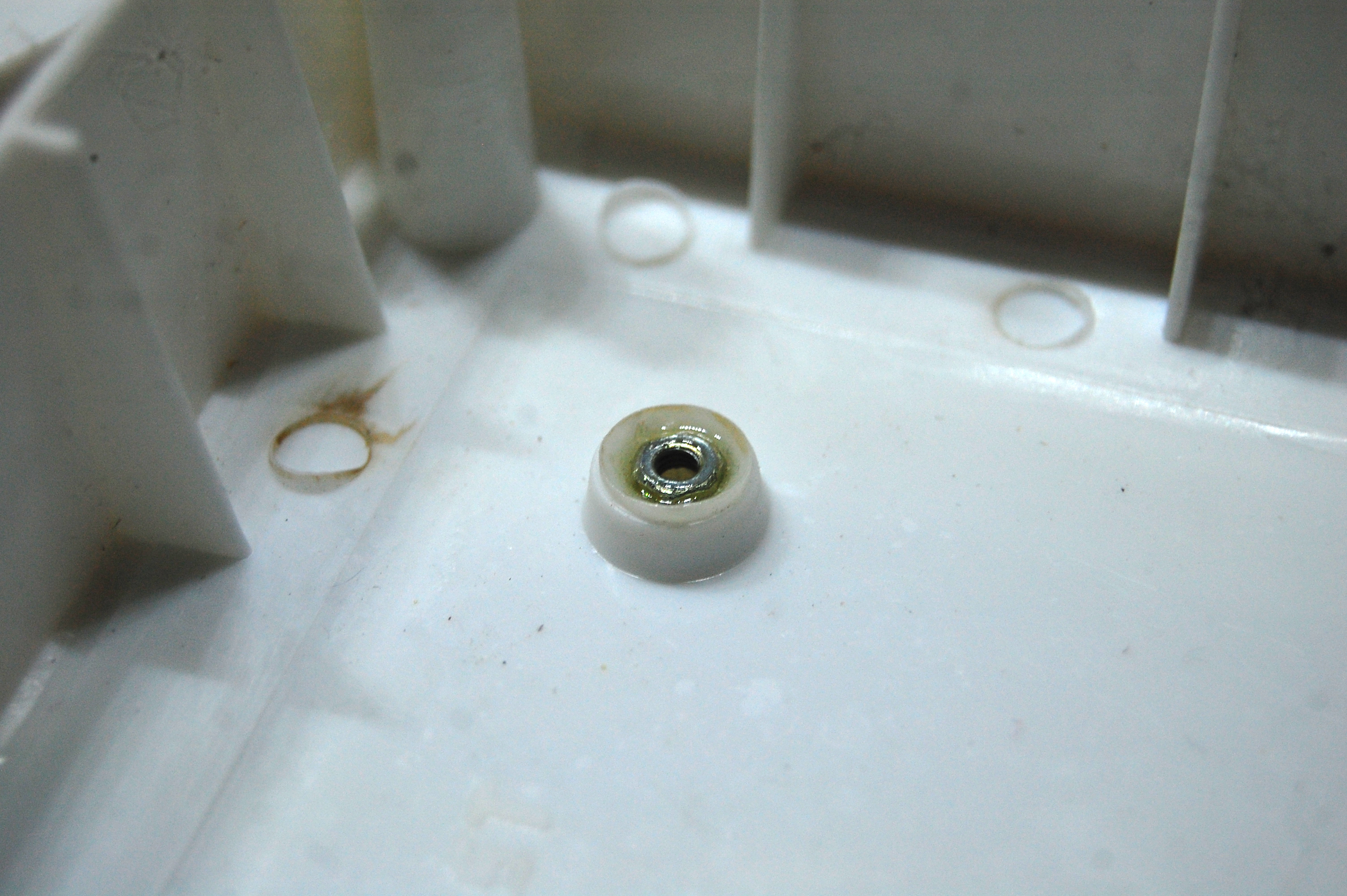
I chose to use switchboard box as an enclosure for the controller as it has pre-drilled holes for mounting and a cover plate. I glued in a nut in each slot by using some epoxy glue. I did the same on the opposite side. This makes sure that the PCB is held securely by the screws. I made small openings at the bottom of the box as shown in the picture for the power cable and the wires going to LED panel.
Downloads
Time for Some Code!
.jpg)
.jpg)
.jpg)
After making the controller board, its time to make it work! Download the sketch attached here and open it in Arduino IDE. Make sure you download and install the library for DS3231 attached here.
Setting up the RTC
- Insert a 2032-type coin cell battery.
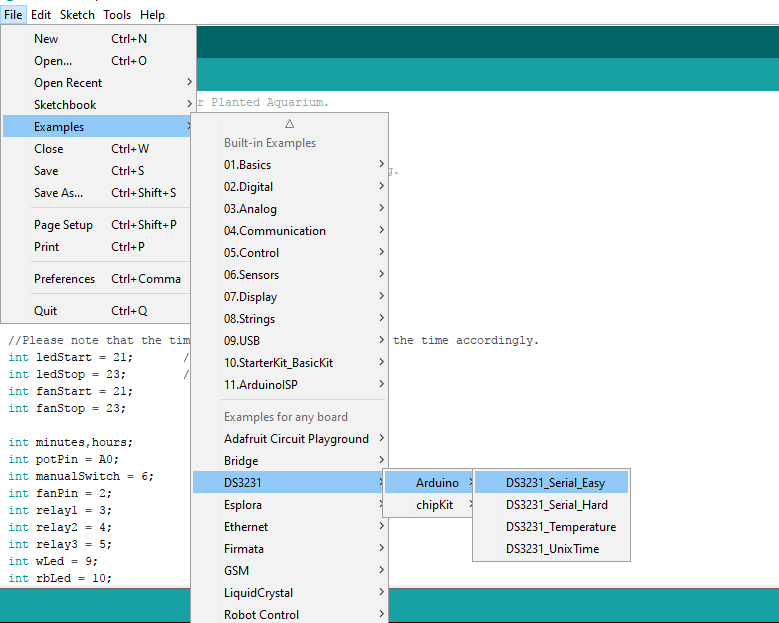
- Open the DS3231_Serial_Easy from the examples as shown.
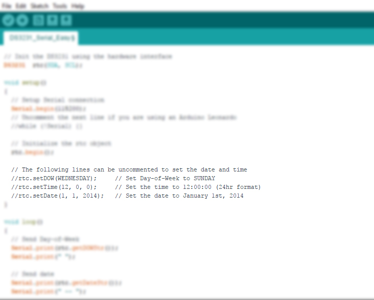
- Uncomment the 3 lines and enter the time and date as shown in the picture.
- Upload the sketch to Arduino and open up the serial monitor. Set the baud rate to 115200. You should be able to see the time which keeps on refreshing every 1 sec.
- Now, unplug the Arduino and plug it in again after few seconds. Look at the serial monitor. It should show the real-time.
Done! RTC has been set up. This step has to be done only once to set the date and time.
Before you upload
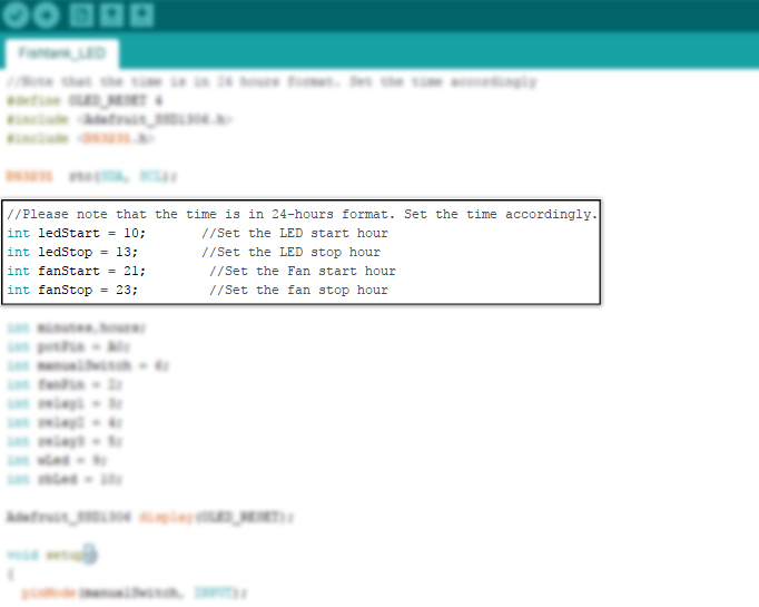
- Set the start time for the LEDs.
- Set the stop time for the LEDs.
- Set the start time for the fan.
- Set the stop time for the fan.
Note: The time is in 24-hours format. Set the time accordingly.
As mentioned earlier, the LEDs won't turn ON to full brightness. For example, If you set LED start time as 10:00 AM then the LEDs will slowly turn ON and reach its full brightness till 11:00 AM and will remain constant till the stop time is reached. This is to simulate the sunrise and sunset. Red and Blue LEDs are constant. They remain completely ON during the entire time.
That's all you have to set. Upload the code to the Arduino. Now, no need to remember to turn your aquarium lights ON and OFF anymore!
I cannot get some shots of it from the actual fish tank in which it will be mounted as I have not yet set it up.I will update the instructable as soon as I get all set up!
Hope you enjoyed the build. Make it yourself and have fun! There is always some space for improvement and a lot to learn. Come up with your own ideas.
I will be starting again with planted aquariums after many years. I am not an expert in this field. Feel free to comment any suggestions regarding the build. Thank you for sticking around till the end.