Automated Driveway Gates Version 2
by kgray77 in Circuits > Arduino
467 Views, 3 Favorites, 0 Comments
Automated Driveway Gates Version 2


Hello!
This tutorial is a second version of my previous award winning Automated Driveway Gates project. It includes new upgraded linear actuators that have built-in hall sensors, a new mainboard consisting of an ESP32, a new double motor driver module capable of 15A @ 13.8V per channel, and a new waterproof ultrasonic sensor!
Supplies
The Parts
As I just explained, there are many new and better components in this build.
- 2x PA-04-HS 12V 12A IP65 Hall Effect Linear Actuators ( I also bought both bracket types)
- 1x DFRobot FireBeetle ESP32
- 1x DFRobot 2x15A Motor Driver (now discontinued, but they have a new version capable of 12A per channel)
- 1x DFRobot 50A AC/DC Current Sensor
- 1x DFRobot Waterproof Ultrasonic Sensor
- 1x LD1117v33 3.3V 800mA voltage regulator IC
- 2x 10µF Electrolytic Capacitors for the regulator
- 1x 12V 350W Power Supply
- 2x 12V IP65 RGB LED Strips
- 4x NPN MOSFETs (I use STP90NF03L)
DFRobot
DFRobot
Dfrobot is an awesome electronics company! They kindly sponsored their parts to me for this project. They have anything you could need for any project of every type! You can check my other projects for more awesome things you can build with their parts. Check them out here! https://www.dfrobot.com
Wiring
Wiring
The wiring may look complicated, but is pretty straightforward once you dive in 😉.
Motor Driver - FireBeetle:
- M2Speed - IO17
- M2Dir - IO13
- M1Speed - IO16
- M1Dir - IO14
- +5V - VCC
- GND - GND
Ultrasonic Sensor - FireBeetle:
- +3.3V - +3.3V
- GND - GND
- RX - IO22
- TX - IO21
Spot Light - FireBeetle:
- Transistor Gate - IO12
LED Strips - FireBeetle:
- 1st transistor gate - IO25
- 2nd transistor gate - IO27
- 3rd transistor gate - IO5
Magnet Lock - FireBeetle:
- Transistor Gate - IO2
Current Sensor - FireBeetle:
- AO - A0
If this description doesn't make sense (I would totally agree), you can follow the schematic that I drew:
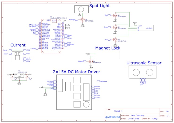
Schematic
Blynk
Blynk
Blynk has been updated 😣! Personally, I don't like the new version; it is harder to use, has less features than the previous one, and is pricey.
This is how the desktop template should look when completed:
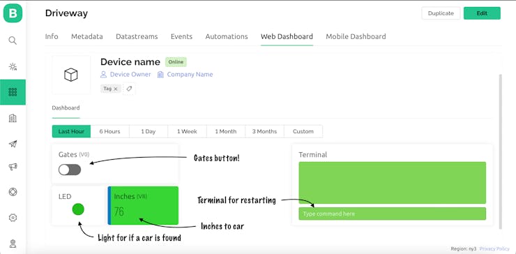
Blynk Desktop Dashboard
Here is the mobile app Template:
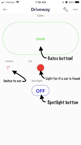
Mobile App Dashboard
If you need help setting up Blynk, refer to the documentation found here:
Code Description
Code Description
The code is quite long for this project! Keep in mind that you will probably have to change some things to get it to work how you would like for your setup. For example, my left actuator seemed to open slower than it closed, so I had to adjust the opening and closing functions to account for that.
#define BLYNK_TEMPLATE_ID "************"
#define BLYNK_DEVICE_NAME "********"
#define BLYNK_AUTH_TOKEN "*******************************"
#define BLYNK_PRINT Serial
First, we have to setup the Blynk credentials. Enter your template id, device name, and auth token on the indicated lines.
#include <WiFi.h>
#include <WiFiClient.h>
#include <BlynkSimpleEsp32.h>
#include <WiFiUdp.h>
#include <ArduinoOTA.h>
#include <SoftwareSerial.h>
Next, all of the libraries are included that we need; WiFi, Blynk, OTA, and software serial.
#define motorAspeed   16//D11
#define motorBspeed   17//D10
#define motorAdir     14//D6
#define motorBdir     13//D7
#define hall          26//D3
#define ultra1        22
#define ultra2        21
#define currentIn     A0
#define pinRed        D4
#define pinGreen      D3
#define pinBlue       4//D12
#define magnet        D9//D13
#define light         4//D12
Here, we define what pins go to which parts. Any numbers not beginning in "D" are "IO" pins on the FireBeetle.
/* Current Sensor (currently not working)
const int numReadings = 30;
float readings[numReadings];      // the readings from the analog input
int inde = 0;                  // the inde of the current reading
float total = 0;                  // the running total
float average = 0;                // the average
float currentValue = 0;
*/
Here are the current sensor readings and variables, but this part isn't working at the time of this writing. I hope to update it soon!
int ppi = 300; //pulses per inch (for the PA-04 Linear Actuator).  Change this according to your specs.
int usedAct = 6; //inches of actuator used
char ssid[] = "************";//WiFi network name
char pass[] = "********";//WiFi network password
All of these variables have to be changed! First is the ppi variable, which stands for "Pulses Per Inch". This value is dependent on the linear actuator you use, but is the amount of pulses from the hall sensor per inch. Next, is the usedAct variable. This variable is the amount of inches on the linear actuator that are used. You may need to adjust this number several times to get the desired effect. Lastly, are the WiFi credentials. Enter you WiFi network name and password that you would like your module connected to.
//Gate button value for Blynk
int button;
int timer;
//current sensor value
float voltage;
//ultrasonic sensor
unsigned char data[4] = {};
float distance;
float inches;
int car;
int carDist = 24;//alter this value! This value is distance in inches before something is activated
int tim = 10000;
long hallCount;
//gate status flag
boolean flag = false;
//LED strip starting values
int red = 255;
int green = 255;
int blue = 255;
These are all of the rest of the variables used. The only one that might need altering, is the carDist variable. This is the amount of inches before a car is defined as being there.
SoftwareSerial ultraSerial;
Here, we define an instance of software serial for the ultrasonic sensor.
BLYNK_WRITE(V0){
  button = param.asInt();
}
BLYNK_WRITE(V1){
  red = param.asInt();
}
BLYNK_WRITE(V2){
  green = param.asInt();
}
BLYNK_WRITE(V3){
  blue = param.asInt();
}
BLYNK_WRITE(V4){
  int spotlight = param.asInt();
  if (spotlight){
    digitalWrite(light, HIGH);
  }
  else {
    digitalWrite(light, LOW);
  }
}
String string;
BLYNK_WRITE(V10) {
  string = param.asStr();
  if (string == "restart"){
    Blynk.virtualWrite(V10, "Restarting...");
    Serial.println("Restarting...");
    delay(2000);
    ESP.restart();
  }
}
These are all of the Blynk functions for receiving values.
//gate status flag
boolean isOpen = false;
This is a Boolean variable to indicate if the gates are open or closed.
//PWM information
const int freq = 5000;
const int resolution = 8;
const int redChannel = 1;
const int greenChannel = 2;
const int blueChannel = 3;
const int motorA = 4;
const int motorB = 5;
PWM on an ESP32 is a little more complicated but more customizable, than on an Arduino. Here, we set the frequency, resolution, and then channels for what needs PWM.
void setup() {
  Serial.begin(115200);
  ultraSerial.begin(9600, SWSERIAL_8N1, ultra1, ultra2, false); // RX, TX
  if (!ultraSerial) { // If the object did not initialize, then its configuraiton is invalid
    Serial.println("Invalid SoftwareSerial pin configuration, check config");
  }
In voidsetup(), we first start the serial for debugging (keep in mind this only works if the device is connected to your PC with a wire; not OTA), start the serial for the ultrasonic sensor, and check to make sure the sensor has started.
//set pinModes
  pinMode(motorAspeed, OUTPUT);
  pinMode(motorBspeed, OUTPUT);
  pinMode(motorAdir, OUTPUT);
  pinMode(motorBdir, OUTPUT);
  pinMode(pinRed, OUTPUT);
  pinMode(pinGreen, OUTPUT);
  pinMode(pinBlue, OUTPUT);
  pinMode(hall, INPUT_PULLUP);
  pinMode(currentIn, INPUT);
  pinMode(magnet, OUTPUT);
  pinMode(light, OUTPUT);
Next, we set the pinmodes for everything; they are all outputs except for the hall sensor, which is an input pull-up.
//attach PWM channels to the correct pins
  ledcAttachPin(pinRed, redChannel);
  ledcAttachPin(pinGreen, greenChannel);
  ledcAttachPin(pinBlue, blueChannel);
  ledcAttachPin(motorAspeed, motorA);
  ledcAttachPin(motorBspeed, motorB);

  //setup the PWM channels
  ledcSetup(redChannel, freq, resolution);
  ledcSetup(greenChannel, freq, resolution);
  ledcSetup(blueChannel, freq, resolution);
  ledcSetup(motorA, freq, resolution);
  ledcSetup(motorB, freq, resolution);
Here, the PWM is setup! First, we attach the pins to the correct channels, then we setup the channel frequency and resolution for each one.
//connect to the WiFi
  wificonnect();

  //Start Blynk
  Serial.println("Blynk Starting...");
  Blynk.config(BLYNK_AUTH_TOKEN);

  //Start OTA
  Serial.println("OTA Starting...");
  OTAStart();
These three parts get our wireless up and running. First, we connect to the WiFi, then we configure Blynk, and finally, we start the OTA. The OTA default password is "maker"; this can be changed in the OTAStart(); function.
//open the gates all the way at the beginning to set the hall sensor back at 0
  Serial.println("Begin opening...");
  delay(1000);
  beginOpen();
  hallCount = ppi*usedAct;
  isOpen = true;
  Serial.println("Attaching interrupt...");
  attachInterrupt(digitalPinToInterrupt(hall), interruptName, FALLING);//Interrupt initialization
  //then close to the correct place, keeping track of the hall count
  Serial.println("Closing to correct place...");
  close();
  Serial.println("Done closing!");
  Serial.println("Ready");
  isOpen = false;
}
The gate setting up finishes the voidsetup(); function. First, the gates are opened all of the way without using the hall sensor. This serves like a form of calibration, because when the gates are fully opened to their limit, we then know where the hall sensor is at! Next, we attach the hall sensor, because if we attach the hall sensor interrupt before the beginning opening function, the hall sensor will start counting, and we do not want to do that for the calibration. Now we can close to the correct place counting the hall pulses as we go, to make sure they shut correctly. Now that they are shut, we set the gate status boolean to false, to indicate that the gates are successfully closed.
void loop() {
  //if WiFi was lost, reconnect
  if (WiFi.status() == WL_CONNECTION_LOST){
    Serial.println("Connection lost...");
    wificonnect();
  }
  //handle the OTA
  ArduinoOTA.handle();
In voidloop(), we first check our WiFi connection, and handle OTA.
//ultrasonic sensor reading
  for (int i=0;i<4;i++){
    Serial.println("Checkdist();");
    ArduinoOTA.handle();
    checkDist();
  }
  Blynk.virtualWrite(V8,inches);
  if (inches <= carDist){
    Serial.println("Car");
    Blynk.virtualWrite(V9, HIGH);
  }
  else {
    Blynk.virtualWrite(V9, LOW);
  }
Here, we read the ultrasonic sensor several times to make sure we get a good reading. Then we send the value to Blynk, and check to see if there is a car and update the LED on Blynk accordingly.
//if Blynk button pressed, switch the flag
  if (button == HIGH){
    flag = !flag;
  }
  //check to see if the flag is true, then check if the gates are closed and open them
  if (flag == true && isOpen == false) {
    digitalWrite(magnet, LOW);
    delay(100);
    open();
    isOpen = true;
  }
  //else, check to see if the gates are open, and close them
  else if (flag == false && isOpen == true) {
    close();
    delay(100);
    digitalWrite(magnet, HIGH);
    isOpen = false;
  }
If the Gates button is pressed on Blynk, switch the flag. If the flag is true, and the gates are closed, shut off the magnet, open the gates, and set the status to open! If the flag is false and the gates are open, close them, turn the magnet on, and set the status to closed.
//write the Blynk values to the LED strips
  ledcWrite(redChannel, red);
  ledcWrite(greenChannel, green);
  ledcWrite(blueChannel, blue);

  //run Blynk, yield() to prevent unwanted resets, and delay 1 millisecond to keep track of time
  Blynk.run();
  yield();
  delay(1);
In the last part in the voidloop(), the Blynk values are written to the LED strips, Blynk is ran, and we make sure to yield();. If we don't add the yield, the ESP32 will restart unexpectedly, and can cause problems.
void wificonnect(){
  Serial.println("WiFi Connecting...");
  WiFi.mode(WIFI_STA);
  WiFi.begin(ssid, pass);
  while (WiFi.status() != WL_CONNECTED){
    Serial.print(".");
    delay(1000);
  }
  Serial.println("");
  while (WiFi.waitForConnectResult() != WL_CONNECTED) {
    Serial.println("Connection Failed! Rebooting...");
    delay(5000);
    ESP.restart();
  }
}

void checkDist(){
  retry:
  do {
    for (int i = 0; i < 4; i++){
      data[i] = ultraSerial.read();
    }
  }
  while (ultraSerial.read() == 0xff);
  ultraSerial.flush();
  if (data[0] == 0xff) {
    int sum;
    sum = (data[0] + data[1] + data[2]) & 0x00FF;
    if (sum == data[3]) {
      distance = (data[1] << 8) + data[2];
      if (distance > 20) {
        inches = distance / 25.4; //mm to inches
        Serial.print(distance / 10);
        Serial.println("in");
      } else {
        inches = 0;
        Serial.println("Below the lower limit");
      }
    } else goto retry;//Serial.println("ERROR");
  }
  delay(100);
}

void beginOpen(){
  bodo:
  digitalWrite(motorAdir, HIGH);
  digitalWrite(motorBdir, HIGH);
  ledcWrite(motorA, 255);
  ledcWrite(motorB, 255);
  yield();
  timer++;
  delay(1);
  while (timer < 24000){
    yield();
    goto bodo;
  }
  timer = 0;
  Serial.println("Done!");
  ledcWrite(motorA, 0);
  ledcWrite(motorB, 0);
}

void open(){
  int times=0;
  hallCount = 0;
  redo:
  digitalWrite(motorAdir, HIGH);
  digitalWrite(motorBdir, HIGH);
  ledcWrite(motorA, 255);
  ledcWrite(motorB, 255);
  while (hallCount < ppi*usedAct){
    yield();
    Serial.print("Hall count: ");
    Serial.println(hallCount);
    goto redo;
  }
  delay(500);
  tedo:
  digitalWrite(motorAdir, HIGH);
  digitalWrite(motorBdir, HIGH);
  ledcWrite(motorA, 255);
  ledcWrite(motorB, 255);
  times++;
  delay(1);
  yield();
  while (times < 7000){
    goto tedo;
  }
  times=0;
  yield();
  ledcWrite(motorA, 0);
  ledcWrite(motorB, 0);
}

void close(){
  hallCount = ppi*usedAct;
  redone:
  digitalWrite(motorAdir, LOW);
  digitalWrite(motorBdir, LOW);
  ledcWrite(motorA, 255);
  ledcWrite(motorB, 255);
  while (hallCount > 0){
    yield();
    Serial.print("Hall count: ");
    Serial.println(hallCount);
    goto redone; //goto endy;
  }
  yield();
  ledcWrite(motorA, 0);
  ledcWrite(motorB, 0);
  digitalWrite(motorAdir, HIGH);
  digitalWrite(motorBdir, HIGH);
  Serial.println("Gates closed");
}

void OTAStart(){
  // Port defaults to 8266
  ArduinoOTA.setPort(8266);
  // Hostname defaults to esp8266-[ChipID]
  ArduinoOTA.setHostname("DrivewayESP");
  // No authentication by default .
  ArduinoOTA.setPassword("maker");
  // Password can be set with it's md5 value as well
  // MD5(admin) = 21232f297a57a5a743894a0e4a801fc3
  // ArduinoOTA.setPasswordHash("21232f297a57a5a743894a0e4a801fc3");
  ArduinoOTA.onStart([]() {
  //open();
  String type;
  if (ArduinoOTA.getCommand() == U_FLASH) {
    type = "sketch";
  } else { // U_FS
    type = "filesystem";
  }
  // NOTE: if updating FS this would be the place to unmount FS using FS.end()
  Serial.println("Start updating " + type);
  });
  ArduinoOTA.onEnd([]() {
    Serial.println("\nEnd");
  });
  ArduinoOTA.onProgress([](unsigned int progress, unsigned int total) {
    Serial.printf("Progress: %u%%\r", (progress / (total / 100)));
  });
  ArduinoOTA.onError([](ota_error_t error) {
  Serial.printf("Error[%u]: ", error);
  if (error == OTA_AUTH_ERROR) {
    Serial.println("Auth Failed");
  } else if (error == OTA_BEGIN_ERROR) {
    Serial.println("Begin Failed");
  } else if (error == OTA_CONNECT_ERROR) {
    Serial.println("Connect Failed");
  } else if (error == OTA_RECEIVE_ERROR) {
    Serial.println("Receive Failed");
  } else if (error == OTA_END_ERROR) {
    Serial.println("End Failed");
  }
  });
  ArduinoOTA.begin();
  Serial.println("Ready");
  Serial.print("IP address: ");
  Serial.println(WiFi.localIP());
}

ICACHE_RAM_ATTR void interruptName() {
  if (isOpen == false){
    hallCount++;
    if (hallCount >= ppi*usedAct){
      //ledcWrite(motorA, 0);
      //ledcWrite(motorB, 0);
      digitalWrite(hall, HIGH);
      hallCount = ppi*usedAct;
      //delay(1000);
    }
  }
  else if (isOpen == true){
    hallCount--;
    if (hallCount <= 0){
      ledcWrite(motorA, 0);
      ledcWrite(motorB, 0);
      digitalWrite(hall, HIGH);
      hallCount = 0;
      //delay(1000);
    }
  }
  //currentVal();
}
These are all of the functions I made to simplify the code. Notice how the last function is different? That is the interrupt function. For more about interrupts on ESP32, check out this link:
https://lastminuteengineers.com/handling-esp32-gpio-interrupts-tutorial/
In Action
In Action
Here is the finished box:
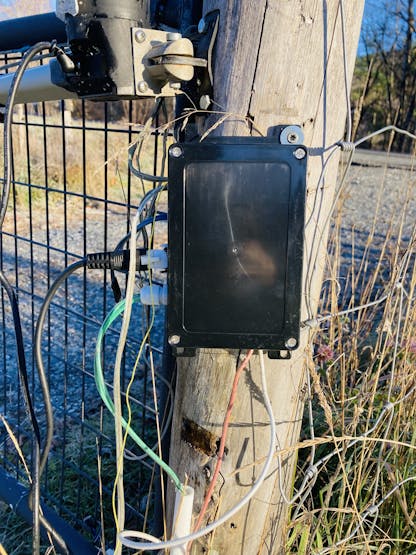
Finshed box with everything wired.
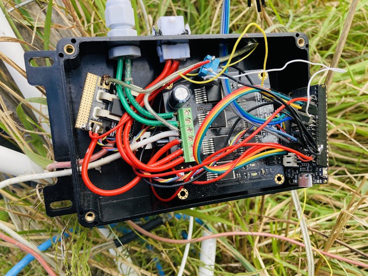
Inside of finished box
A GIF:
GIF of gates opening (in real time, no fast forward)
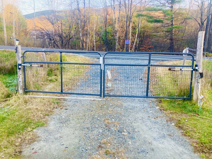
Photos of gates:
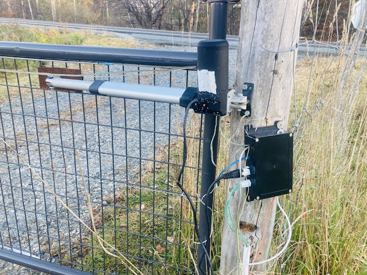
Right actuator and electrical box
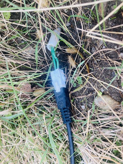
Left actuator connection (wires go under the driveway)
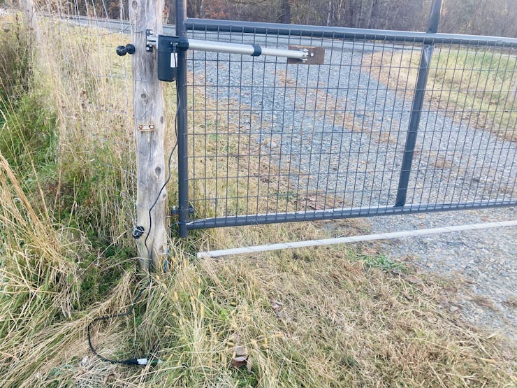
Left Actuator

Ultrasonic Sensor
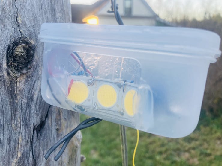
Spot light (3x 36V LEDs)
Complete!
Wrapping Up
Wrapping Up
That was all for this tutorial! If you liked it, give it a thumbs up! Please feel free to post in the comments for any questions, ideas, advice, suggestions, and so on!
Check out this link for more awesome projects: