Automated Arduino Nightlight Using Photoresistors
by TechMartian in Circuits > Arduino
8961 Views, 14 Favorites, 0 Comments
Automated Arduino Nightlight Using Photoresistors
This is the fifth module in a series of lesson for using the Arduino 101 ranging from beginner to advanced skills.
This is a hands free nightlight that will automatically turn on when it is dark.
In this project we will be using photoresistors, whose resistance values varies depending on the amount of light input, to detect the light level. When the level is below a certain calibration threshold it turns on an LED automatically.
Tools and Materials
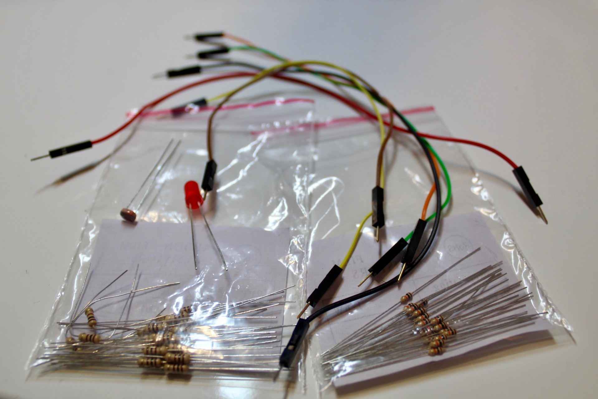
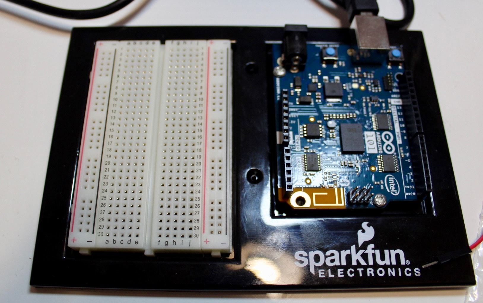
- Arduino 101 or Arduino Uno
- Breadboard
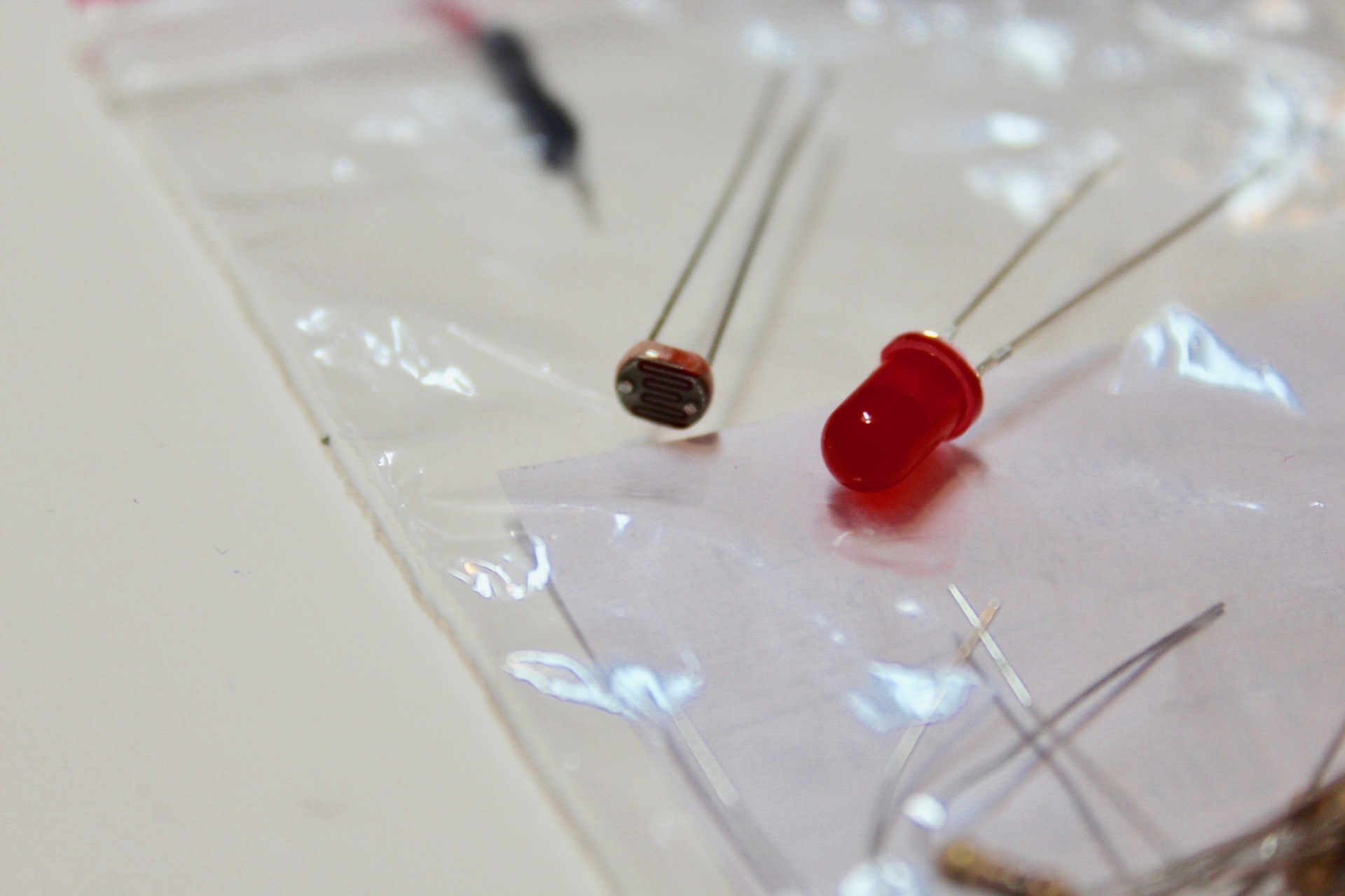
- LED
- LDR or photoresistor
- Jumper Wires
- 100 Ω Resistor
- 10K Ω Resistor
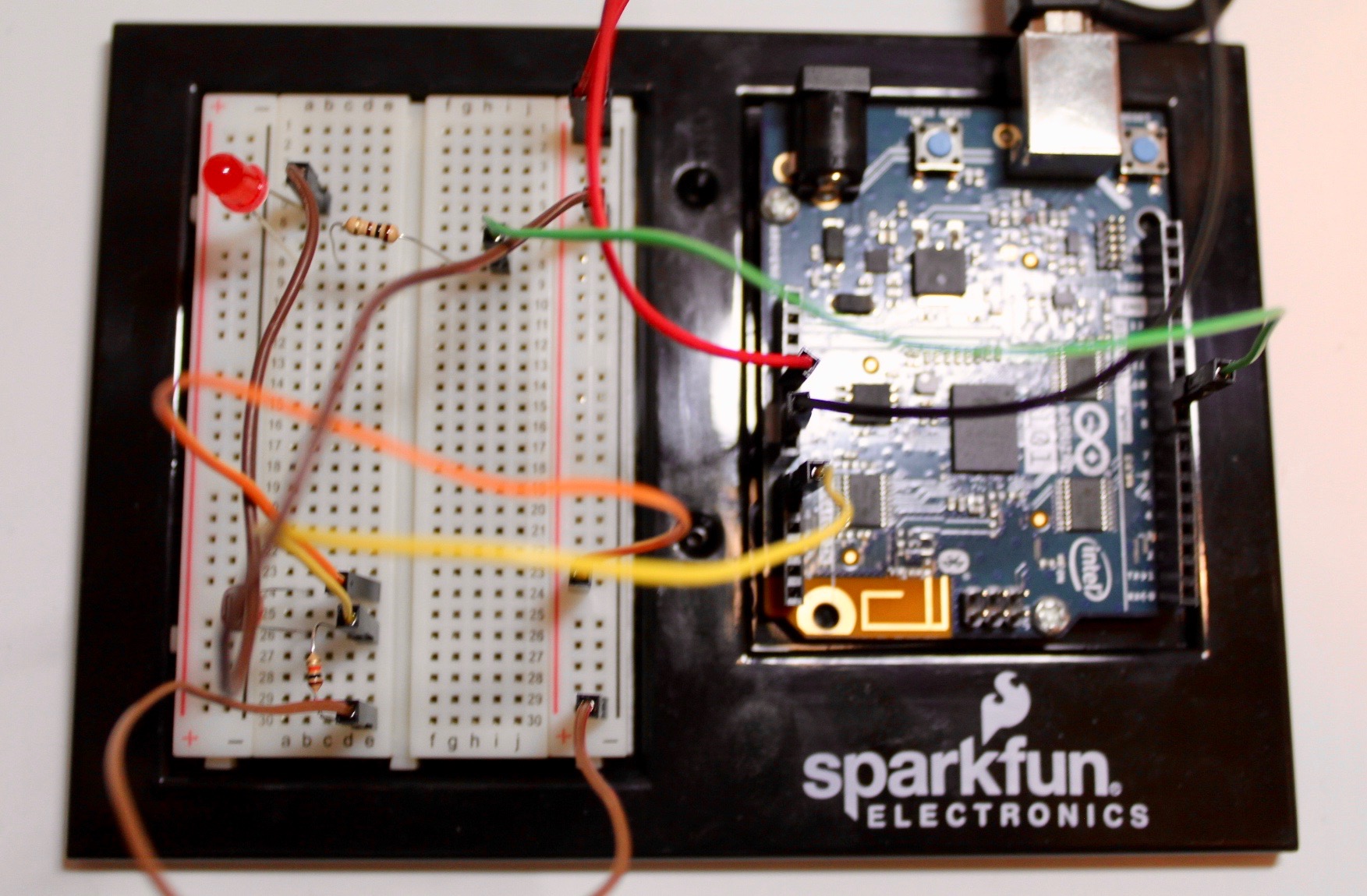
Circuit
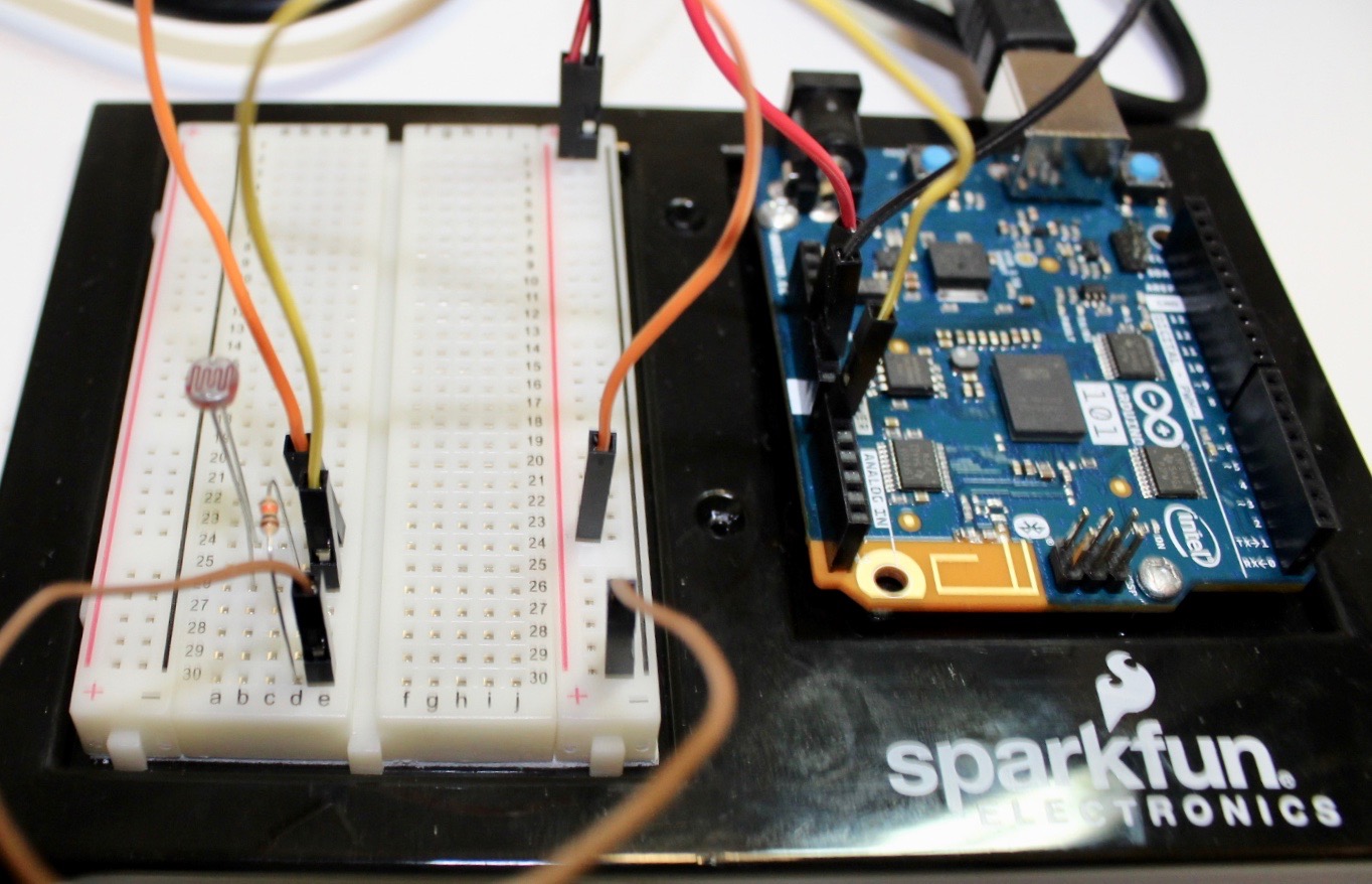
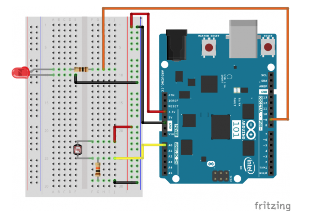

Firstly, we need to wire the Arduino Power to the breadboard
- Connect the 3.3V pin of the Arduino to any pin in the red power rail of the breadboard with a red jumper wire.
- Connect the any GND pin of the Arduino to any pin in the black rail of the breadboard with a black jumper wire.
Then, we will wire the circuit for the LED.
- Connect the negative pin of the LED (flat edge) to the black ground rail of the breadboard with a brown jumper wire.
- Connect the positive pin of the LED to a 100Ω resistor and then connect in series to the red power rail of the breadboard with an orange jumper wire
And last but not least, we will connect the photoresists to the Arduino
- The photoresistor changes resistance, but an Arduino reads voltages. However, due to Ohm's law we can use a voltage divider (one of the most important basic circuits) to read this change in resistance as a change in voltage form the relationship V = IR, where I is current and R is resistance.
- Connect one of the photoresistor pins to a 10k resistor and connected in series to ground, and also connect the pin to A0 of the Arduino.
- Connect the other pin to the red power rail on the breadboard.
Coding
// As usual, we'll create constants to name the pins we're using.
// This will make it easier to follow the code below.
const int sensorPin = 0; const int ledPin = 9;
// We'll also set up some global variables for the light level a calibration value and //and a raw light value int lightCal; int lightVal;
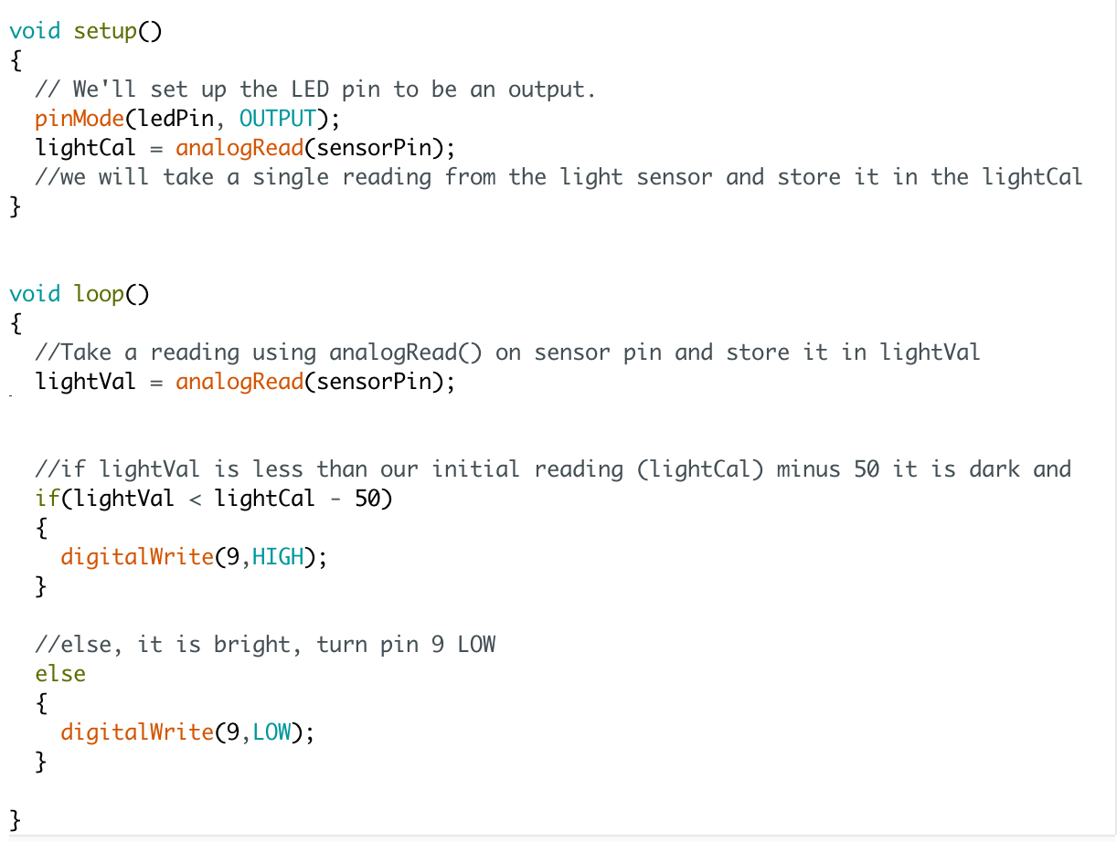
void setup() { // We'll set up the LED pin to be an output. pinMode(ledPin, OUTPUT); lightCal = analogRead(sensorPin); //we will take a single reading from the light sensor and store it in the lightCal //variable. This will give us a prelinary value to compare against in the loop }
void loop() { //Take a reading using analogRead() on sensor pin and store it in lightVal lightVal = analogRead(sensorPin);
//if lightVal is less than our initial reading (lightCal) minus 50 it is dark and //turn pin 9 HIGH. The (-50) part of the statement sets the sensitivity. The smaller //the number the more sensitive the circuit will be to variances in light. if(lightVal < lightCal - 50) { digitalWrite(9,HIGH); }
//else, it is bright, turn pin 9 LOW else { digitalWrite(9,LOW); }
}