Pier 9 Guide: Autodesk Inventor HSM to Shopbot Workflow
by Julie Kumar in Workshop > CNC
4144 Views, 33 Favorites, 0 Comments
Pier 9 Guide: Autodesk Inventor HSM to Shopbot Workflow
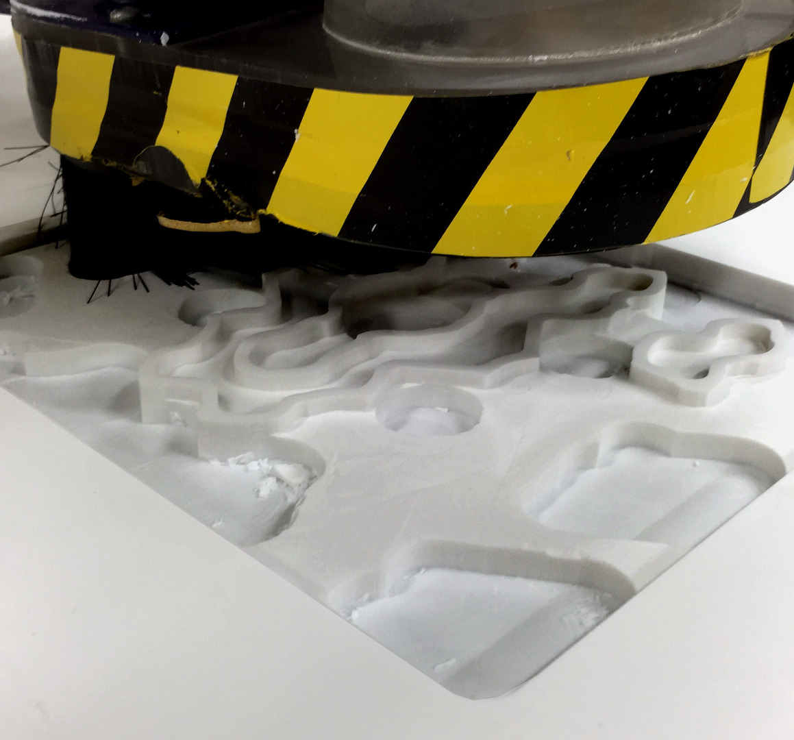
This Instructable is for Workshop Users at Pier 9.
Requirements for using the tools themselves:
- Take General Workshop Safety Class.
- Take ShopBot Basic Use and Safety Class.
This Instructable outlines a logical workflow from model design in Autodesk Inventor HSM to post processing G-code for the Shopbot CNC router. If you're interested in using this workflow for your own project, especially if you'd like more help with the HSM CAM (High Speed Machining) steps--like Setup, Toolpath, and Simulate--this Instructable is for you.
This Instructable can be used in two ways. If you want to use your own design, use my steps as a general guide. You will need to have a basic understanding of parametric modeling in Inventor, so if you've never done this before, try out some tutorials to learn the basics. The steps in this Instructable will offer a good overall foundation for machining strategies that you can apply to your own designs.
However, you can also use this Instructable as a step-by-step guide if you want to just practice CAM without using your own designs yet. I have provided an Inventor .ipt file that you can download below, named CAM_practice_part.ipt.
This Instructable was created at the Pier 9 workshop using Inventor Pro 2016 HSM. However, if you have access to a CNC machine you can use these steps for your own work by downloading Inventor HSM Express for free. This software includes 2D and 2.5D CAM strategies.
Let's begin!
Downloads
Design Your Model
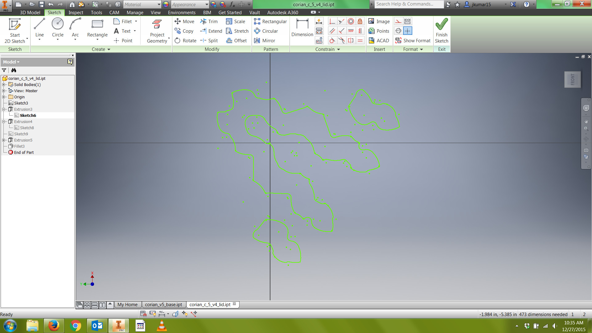
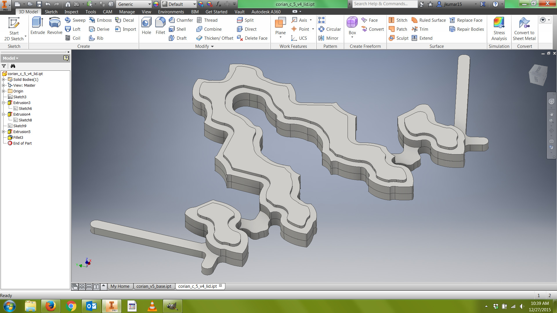
If you're designing your own model, in Inventor start a new sketch and create a design along the xy plane. Use constraints to specify coincident points, parallel and perpendicular relationships, tangents, and dimensions. Constrain one part of your sketch to the origin; this is a general good practice.
In my design, I mirrored my sketches along an axis of symmetry to create a stylized, baroque look.
Finish your sketch and extrude it along the z-axis. Then choose another plane to create a new sketch and repeat until you're happy with your design. Save it as an .ipt file.
Things to consider:
1) Start with a smaller model to test out this workflow. My design fits within a 7" x 7" x 0.5" rectangular prism.
2) Consider the size of your stock. I knew I'd be milling into corian--a very hard plastic commonly used for countertops--and it comes in 0.5" sheets, so that's how I determined the z-height of my model.
3) Consider the size of your smallest endmill. This will determine the level of detail you can get away with in your design. I knew I'd be using a 1/4" flat endmill, so for all my internal angles, I created a fillet with a 0.15" radius. Note that my fillets are a bit larger than the exact radius of my endmill (half of 0.25" is 0.125")--this keeps the endmill from stopping to change directions while it's cutting your part, resulting in a smoother surface finish.
CAM: Setup
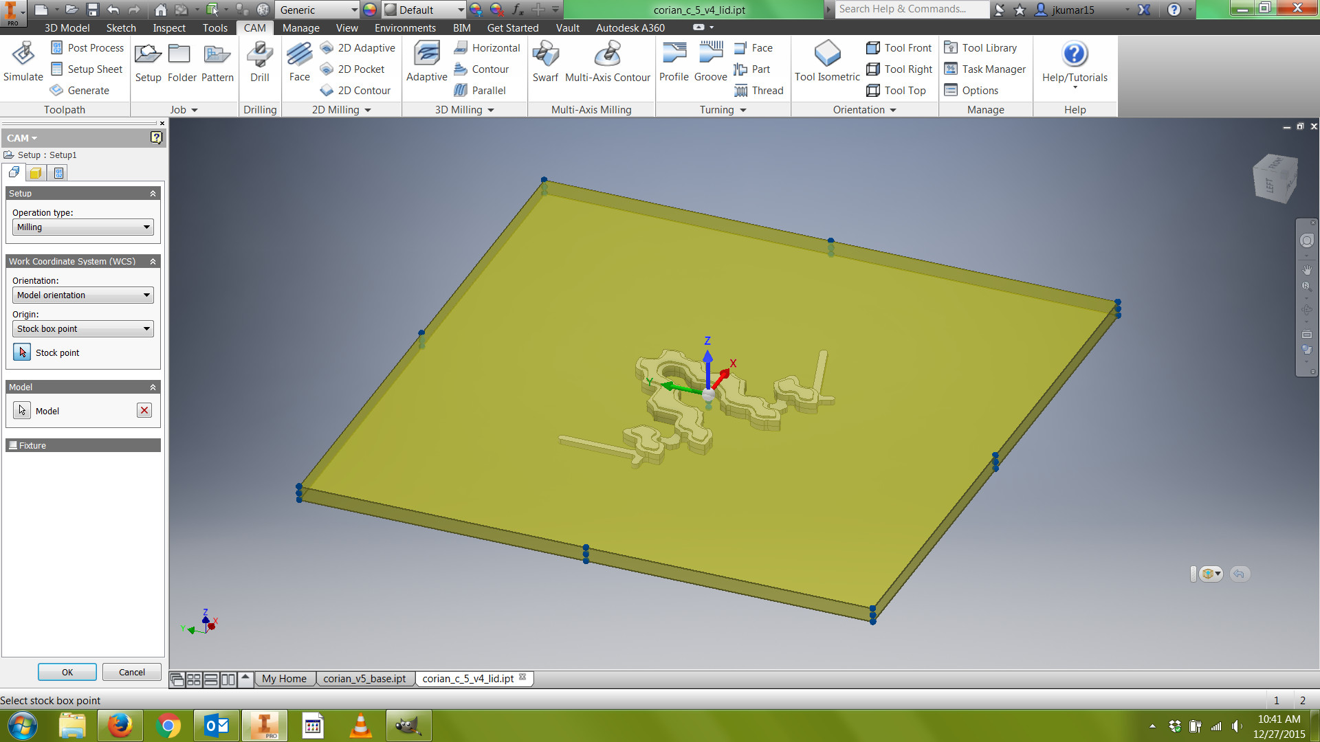
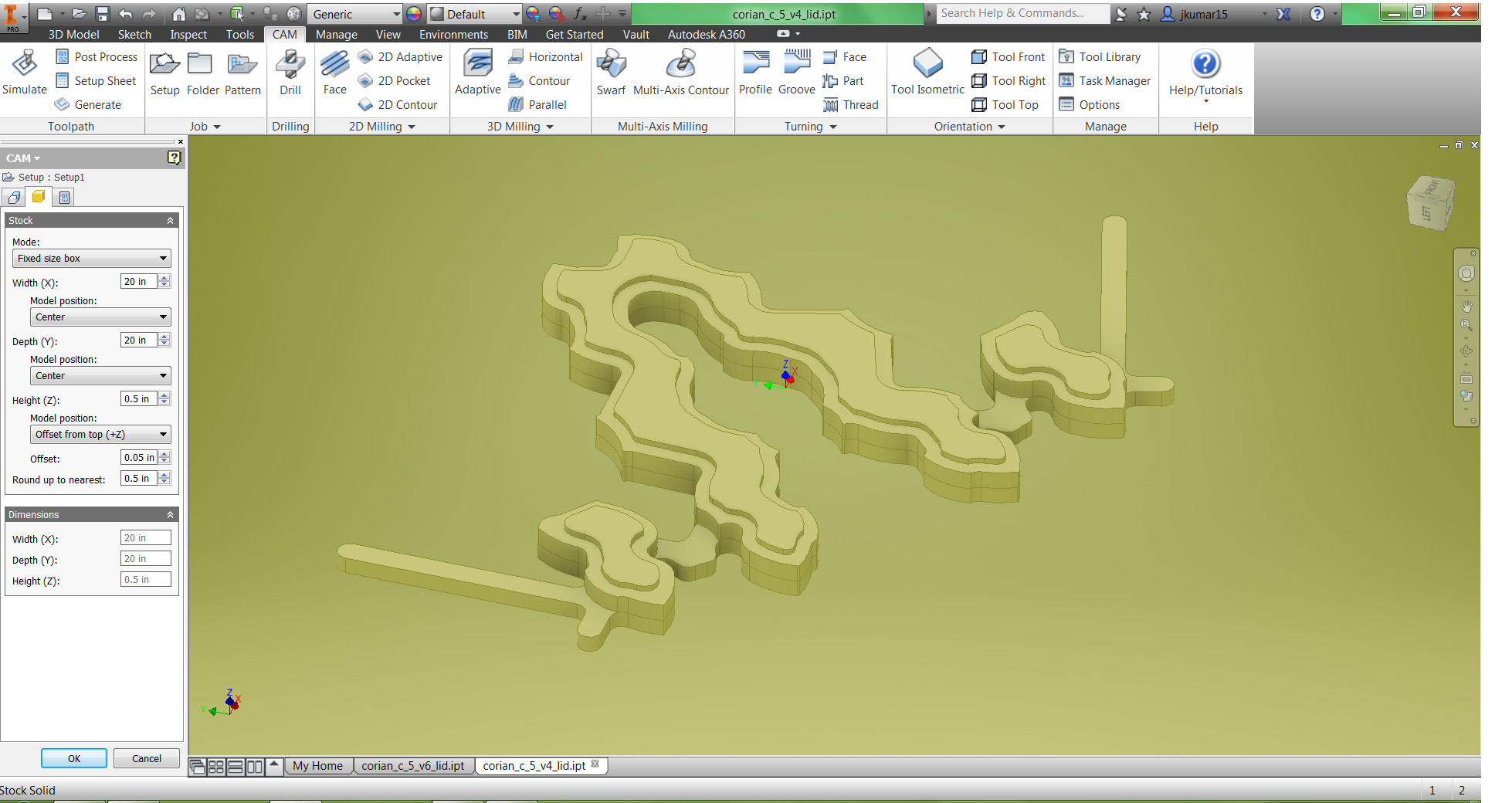
Once your model is finished, or if you're using my solid model, click on the CAM tab at the top of the screen: it's time for Computer Aided Manufacturing.
The three main steps in CAM are Setup, Toolpath, and Simulate.
During the Setup phase, we will determine the size of our stock, the location of our part within our stock, and the location of our Work Coordinate System (WCS). The Work Coordinate System allows the programmer to program the part away from the machine, and tells the CNC machine where the part is located within the machining envelope.
Generally, you want to set your WCS (indicated by the x, y, z triad) on top of your stock, in a corner. However, I knew I'd be milling into a large sheet of corian, so I set my stock dimensions to 20" x 20" x 0.5" and set my WCS on top of the stock in the center of the part. The reason I didn't make my stock just a bit larger than my part was because sometimes the software will automatically send the endmill to the side of the stock, where it thinks there's just empty space, plunge the endmill at rapid speed, and then move in laterally.
This is fine if your physical stock exactly matches the stock in the software. However, if you're milling a small part in a large sheet of material, there might actually be material where the tool is plunging at rapid speed. This could damage the endmill or the machine.
The method above is a good safeguard against this problem. You could also get in the habit of modeling your stock in your design, along with tabs. Either way, keep in mind that simulation mode is very accurate, but it does not show you relative speed changes. This means that if your tool is plunging at rapid speed, in the simulation it might appear as though it's plunging at the proper feed rate.
1) Click the Setup folder in the ribbon on the top of the screen.
2) Ensure that Orientation is set to Model orientation and Origin is set to Stock box point. Choose the center top of your stock for your WCS.
3) Click the Stock tab, change Mode to Fixed size box, and input large, conservative numbers into the X and Y values. For Z, enter the thickness of your stock. I entered 20" for X, 20" for Y, and 0.5" for Z. For model position, I chose "Offset from top (+Z)" and entered an offset of 0.05". This places the model 0.05" below the top of the stock. By positioning the part just a bit below the top of your stock, we can ensure that our part will be flat with consistent dimensions.
4) Click OK to finish Setup.
CAM: Toolpath (Adaptive)
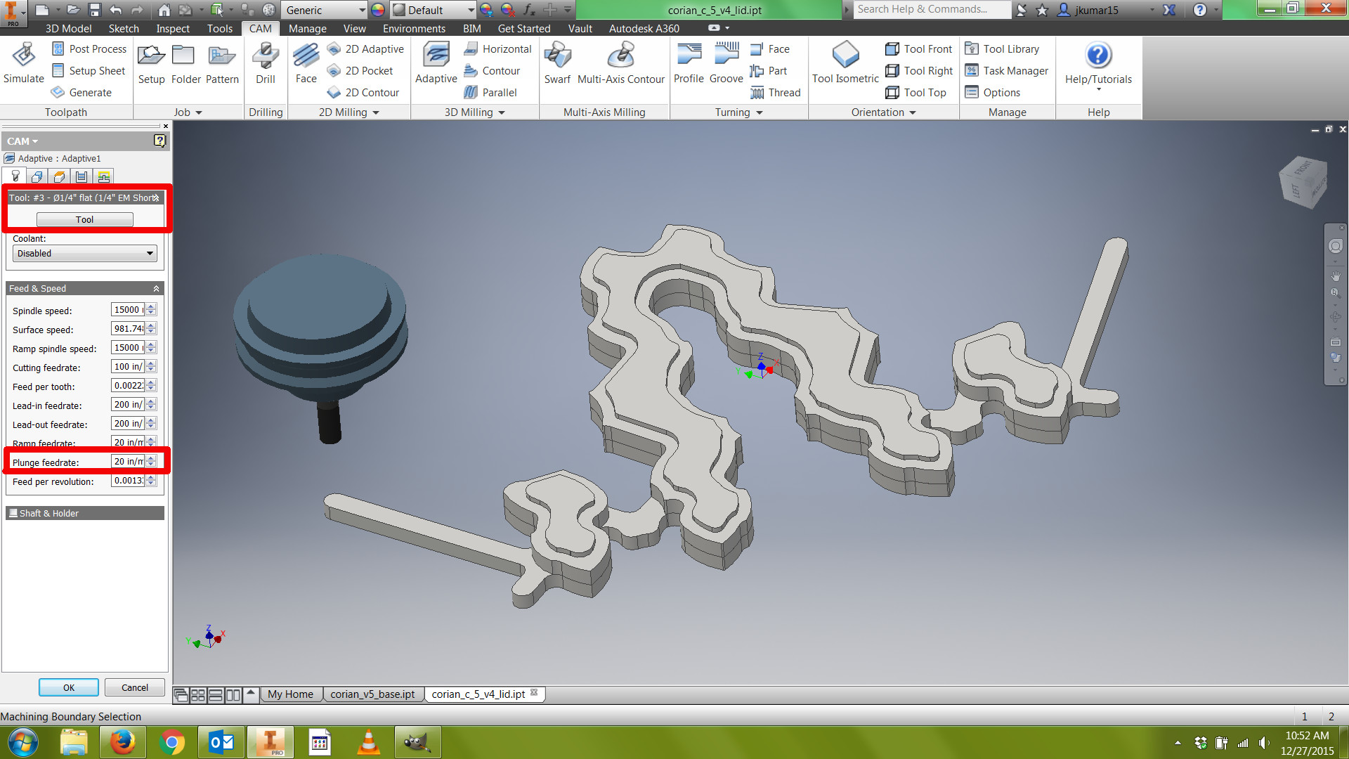
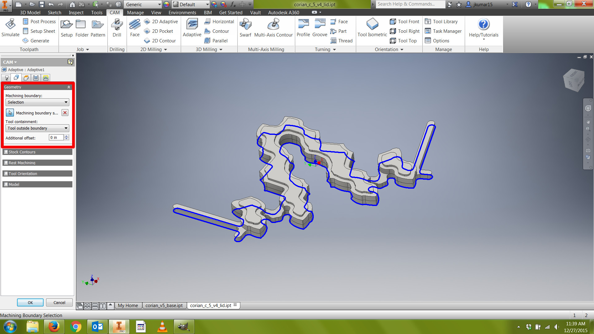
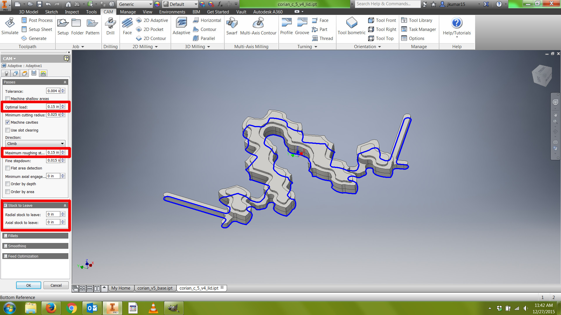
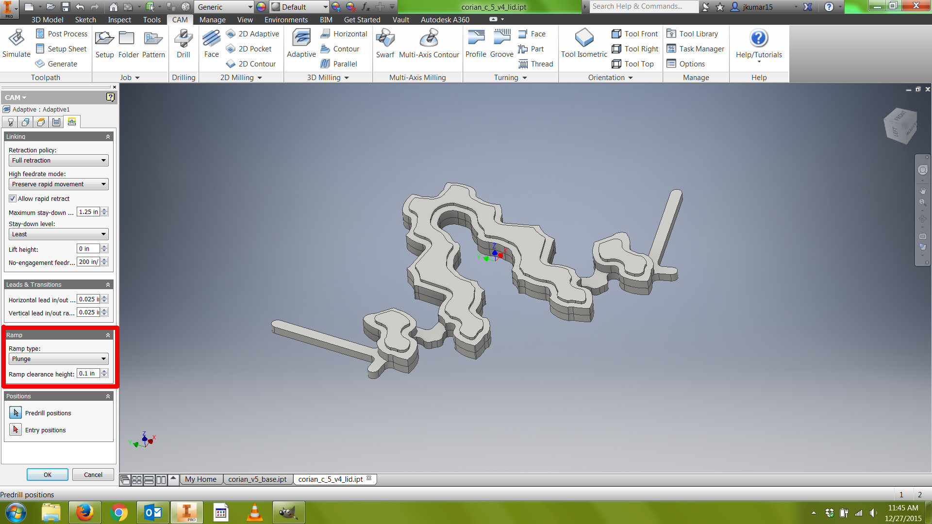
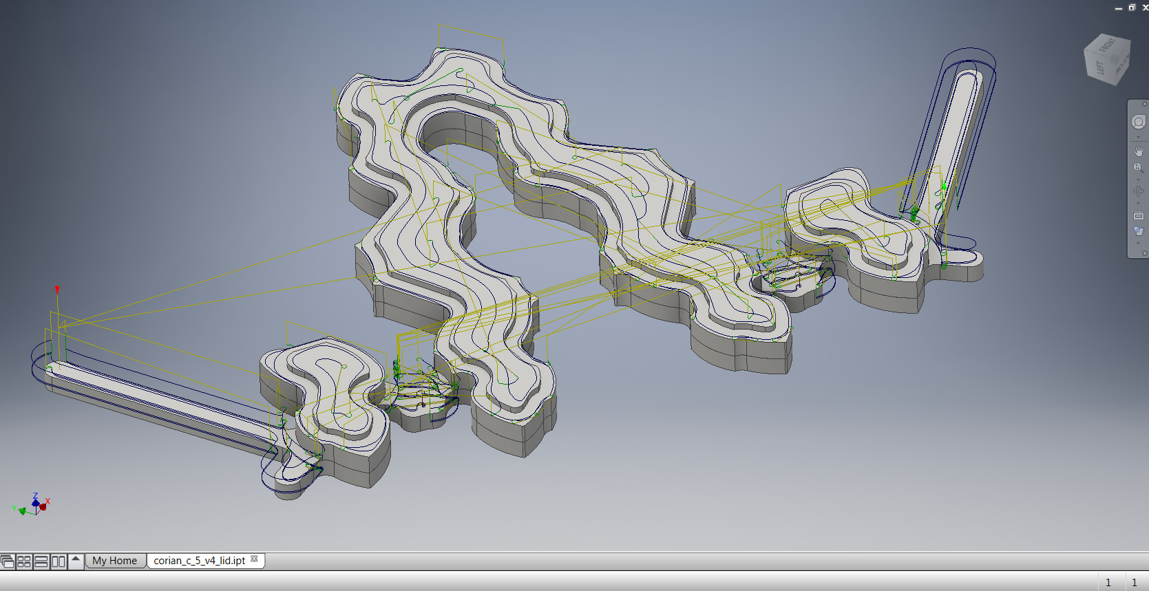
Once you've finished with setup, you'll see a Setup folder in the CAM Feature tree on the left side of your screen. Now when you add toolpaths they'll appear inside this "parent folder."
1. On the ribbon in the 3D milling section, click Adaptive. This is a roughing machining strategy that is used to remove large amounts of material quickly, maintaining a constant load on the tool.
2. Choose an endmill. (If you're at Pier 9, you should download the Pier 9 Tool Library by following the steps in Dan Vidakovich's great Instructable:
https://www.instructables.com/id/Pier-9-Tool-Librar...
Choose an endmill from the DMS Tool Library, not the Haas Tool Library. Though you'll be using the Shopbot, the feeds and speeds should be accurate.) I used a 1/4" flat endmill. Because this design is 2.5D, you don't need an endmill with a radius (though bull nose end mills are also appropriate for this kind of design).
3. Change the plunge feedrate to 20 inches/minute. By default this is set too high, and we won't be using ramp strategies when machining our part so we want a slow, conservative plunge feedrate.
4. Click the contours of the geometry that you want to machine. Choose "Tool outside boundary" to eliminate extra material outside the boundary of this contour. Ensure "Stock Contours" is unchecked.
5. Click the Passes tab, and ensure that the optimal load is at, or less than, 40% of the diameter of your endmill. I chose 0.15". Optimal load is the maximum force that your endmill will encounter while machining your part. If you're using a 1" endmill, decrease your optimal load to 0.05".
6. Change your maximum roughing stepdown to no more than 50-60% of the diameter of your endmill. I chose 0.15".
7. Because this adaptive clearing path will serve as both a roughing and finishing pass, uncheck "stock to leave" or set the radial and axial values at 0. If you prefer to leave stock behind on this toolpath, remember to add another finishing pass using a strategy like 2D pocket with no stock to leave.
8. In the Linking tab, ensure that the ramp style is Plunge. The reason we use Plunge with the Shopbot is because it sometimes has problems calculating the geometry of more complex ramps, such as helices or zig-zags. This is why we changed our Plunge feedrate to a slow rate earlier.
9) Click OK to create toolpath.
CAM: Toolpath (Contour 1)
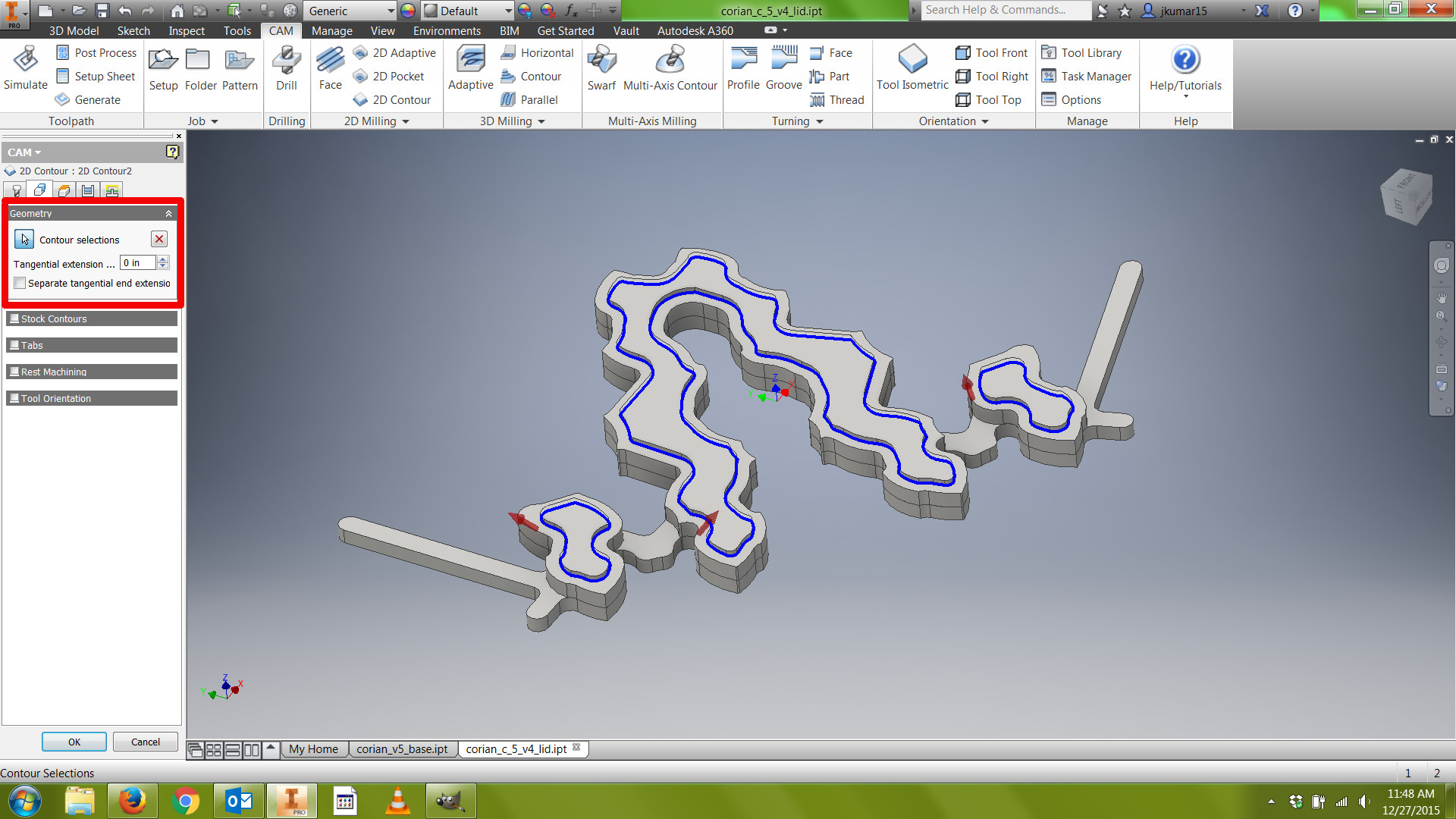
For my design, I had more than one contour that I wanted to machine. I started with the contour near the top surface of my part. If your design is similar, continue with the following steps.
1) On the ribbon in the 2D milling section, click "2D Contour."
2) By default, the last tool used is selected in the "Tool" tab. I used the same tool for all of my toolpaths.
3) Change the Plunge feedrate to 20 inches/minute, as before.
4) Click the geometry of the contour. The rest of the defaults should be fine for this contour toolpath, as we don't have to consider stepdowns or tabs.
5) Click OK to create toolpath.
CAM: Toolpath (Contour 2)
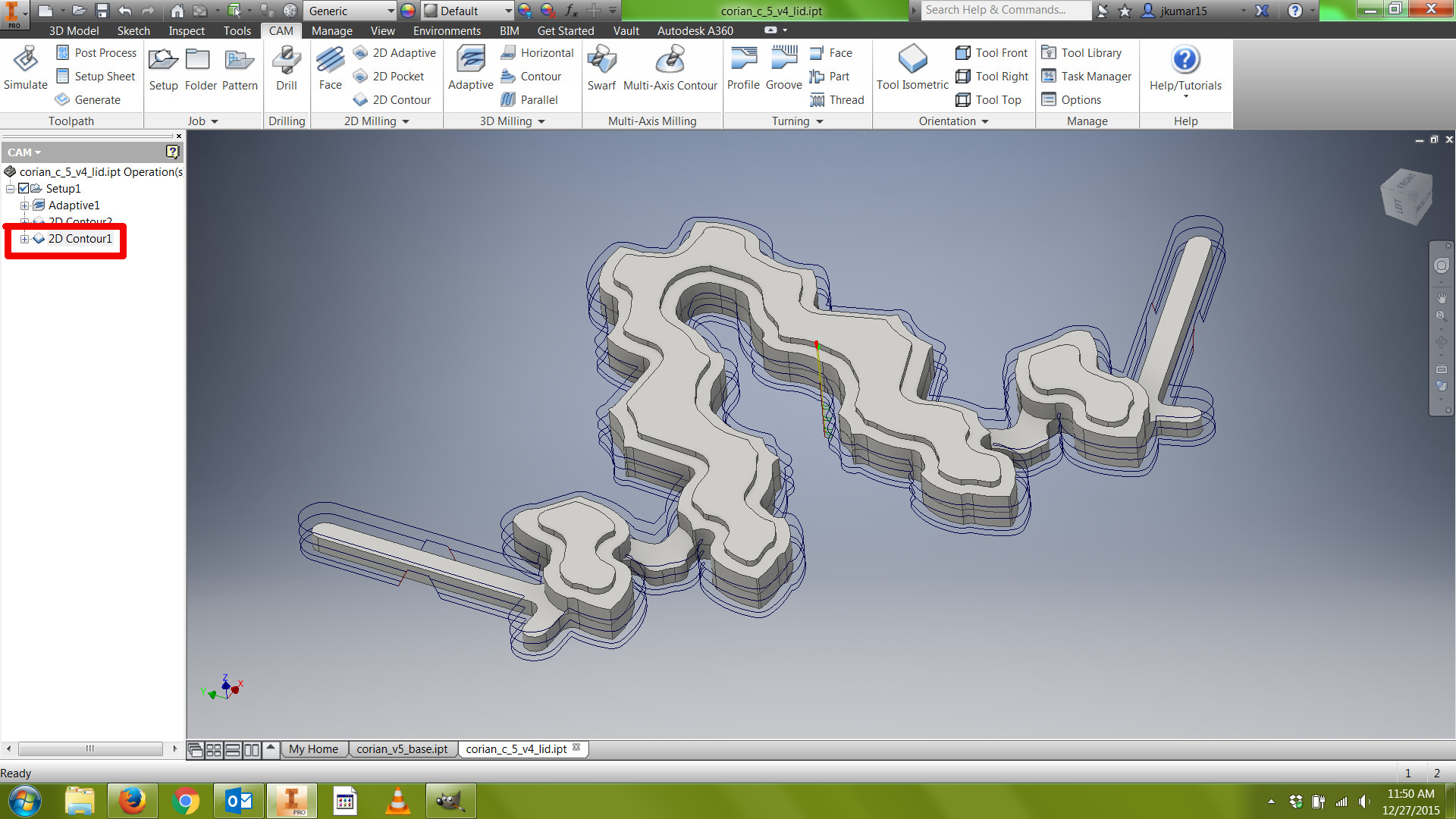
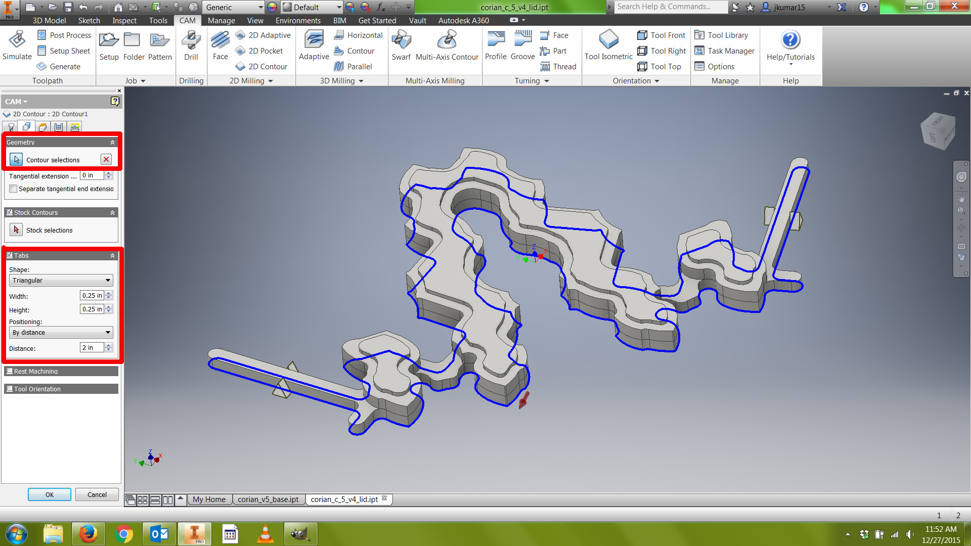
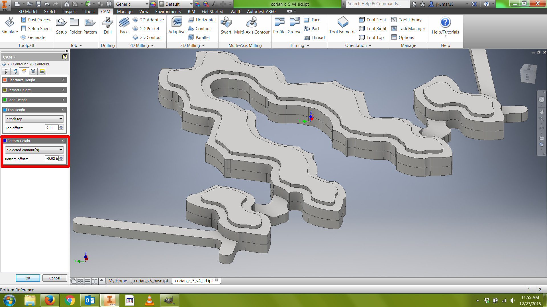
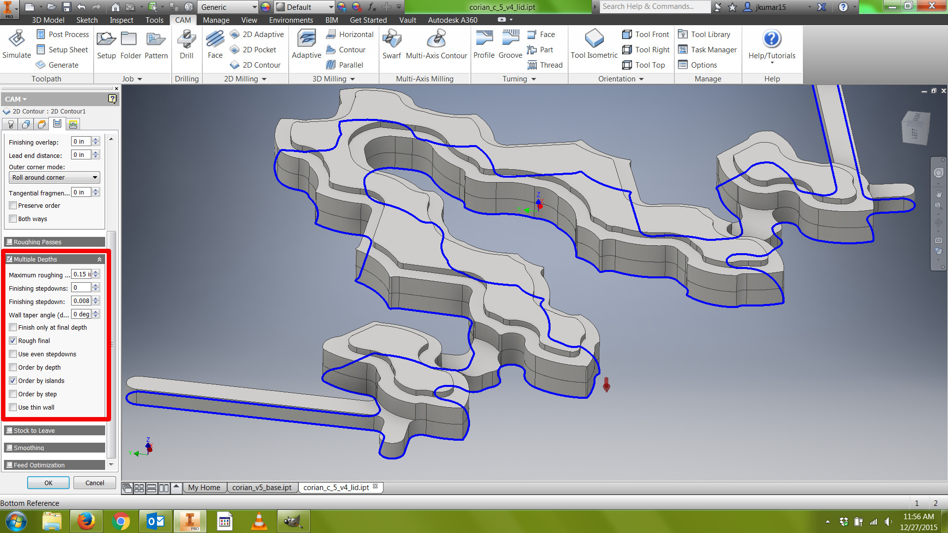
For the final contour that separates the part from the rest of the stock, create a new 2D Contour.
1) By default, the last tool used is selected in the "Tool" tab.
2) Select the geometry of the contour.
3) Click the "Tabs" box to enable this function. We want to create tabs to hold our part in position during this final contour; otherwise, the part will get loose in the stock while the endmill is still moving. The part could go flying, get jammed or damaged, or it could damage the endmill. I chose triangular tabs, 1/4" tall and wide, positioned at a 2" distance. Play around with these settings until you're happy with the tab size and location.
4) In the Heights tab, under Bottom Height, choose a Bottom offset between -0.02" and -.005". This will ensure that the endmill goes all the way through the part and slightly into the spoiler board below, preventing a thin "skin" or flashing from appearing at the bottom edge of the part. If you're using an endmill with a radius (like a bull nose endmill), ensure that the tool is going sufficiently below the bottom edge of the part to remove the webbing that would otherwise be left behind.
5) In the Passes tab, click "Multiple Depths" and choose the same maximum roughing stepdown that you chose in the adaptive toolpath.
6) Click OK to create toolpath.
CAM: Simulate!
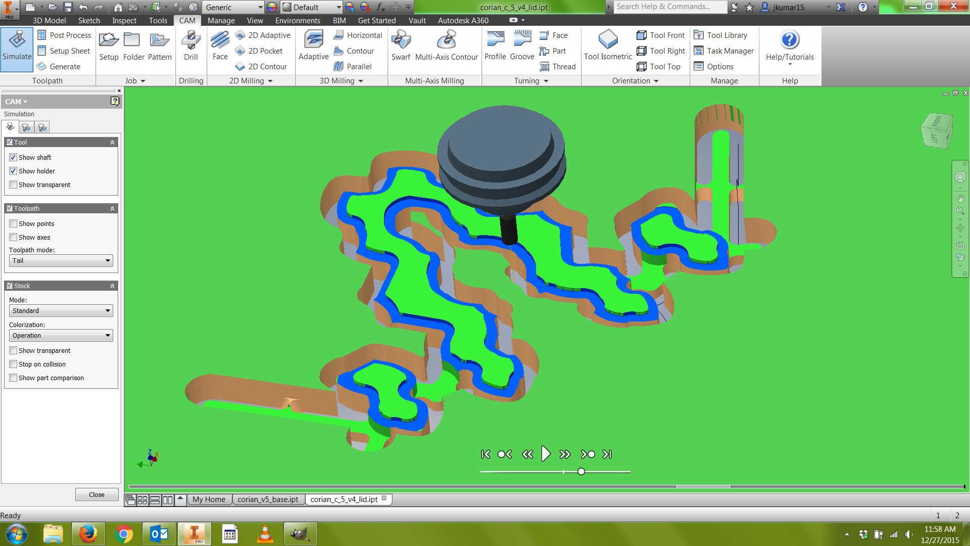
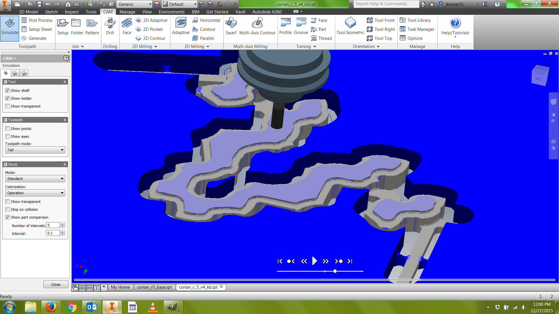
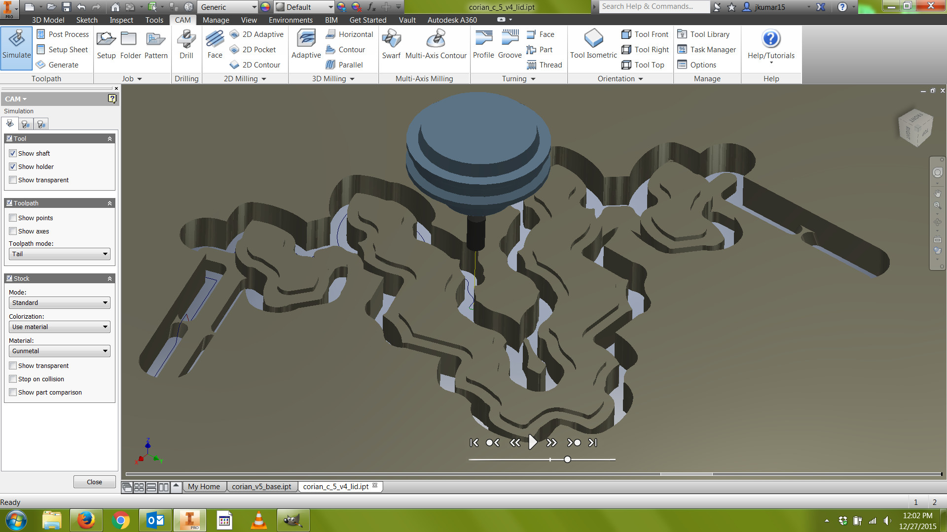
Now that you've created your toolpaths, you want to simulate them to verify your final part.
1) Click Setup in the CAM feature tree. This ensures that you're going to simulate all of the toolpaths within that Setup.
2) Click Simulate in the ribbon above.
3) I like to use Toolpath Mode "Tail," activate my stock in Standard Mode and Colorization: Operation at first, toggling between transparent and opaque stock. Pan and zoom around the model as you watch the simulation, carefully watching the path of the endmill. Especially pay attention to the places where the tool enters and exits your material, and visualize how your stock is going to be clamped to your spoiler board. If you're using toe clamps, will be they be near the toolpath? If you're using screws to hold your part down, is there a chance that the endmill will collide with them? If you must have screws near your part, you can use brass screws, which are softer and not damaging to CNC tools.
If the tool turns red at any point, or you see red marks in the timeline at the bottom of the screen, the software has detected a collision (either between the stock and the tool holder or because the tool is descending below the top of its flutes, where it can no longer cut). In this case, you will need to exit the Simulation and right click on your toolpath to edit it. You may need a longer tool.
4) After you've watched the simulation, exit and then click the 3D Model tab at the top of the screen. In the 3D Model feature tree, right click on "Solid Body" and disable Visibility. Then re-enter the CAM tab, click Setup, and Simulate again. By turning off the visibility of the solid model, we can see exactly how the stock alone will look after it's been machined. Now, click Show Part Comparison. Remaining stock will turn blue, so inspect your model to ensure that there aren't any areas that have been left behind. If you see red areas, this indicates a gouge, which can sometimes be caused by lead-ins and lead-outs (found in the Linking tab in the CAM feature tree). If you set up your toolpaths properly with Plunge for your ramps, this is an unlikely problem.
5) Finally, I recommend turning off Part Comparison, and then viewing your stock as a different material. In Colorization, choose Show Material, and then choose a material. In the image above, I used gunmetal. Looking at your model as a material is another useful way to inspect it, look at the toolpaths, and determine if there are any problems. Remember that your simulation is very accurate--it will show you what you're going to get--so take some time with these steps.
6) Close the simulation.
Post Process
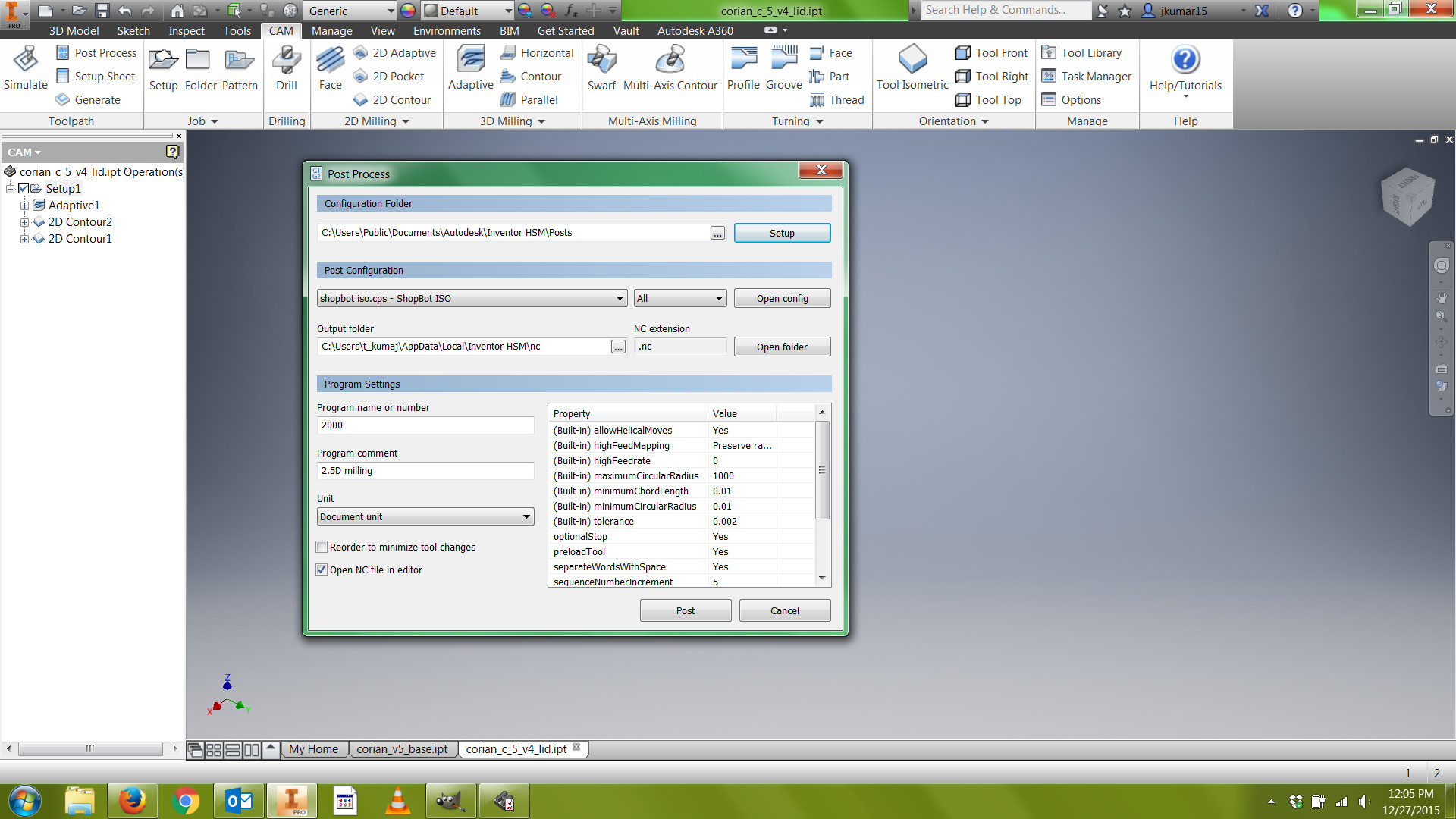
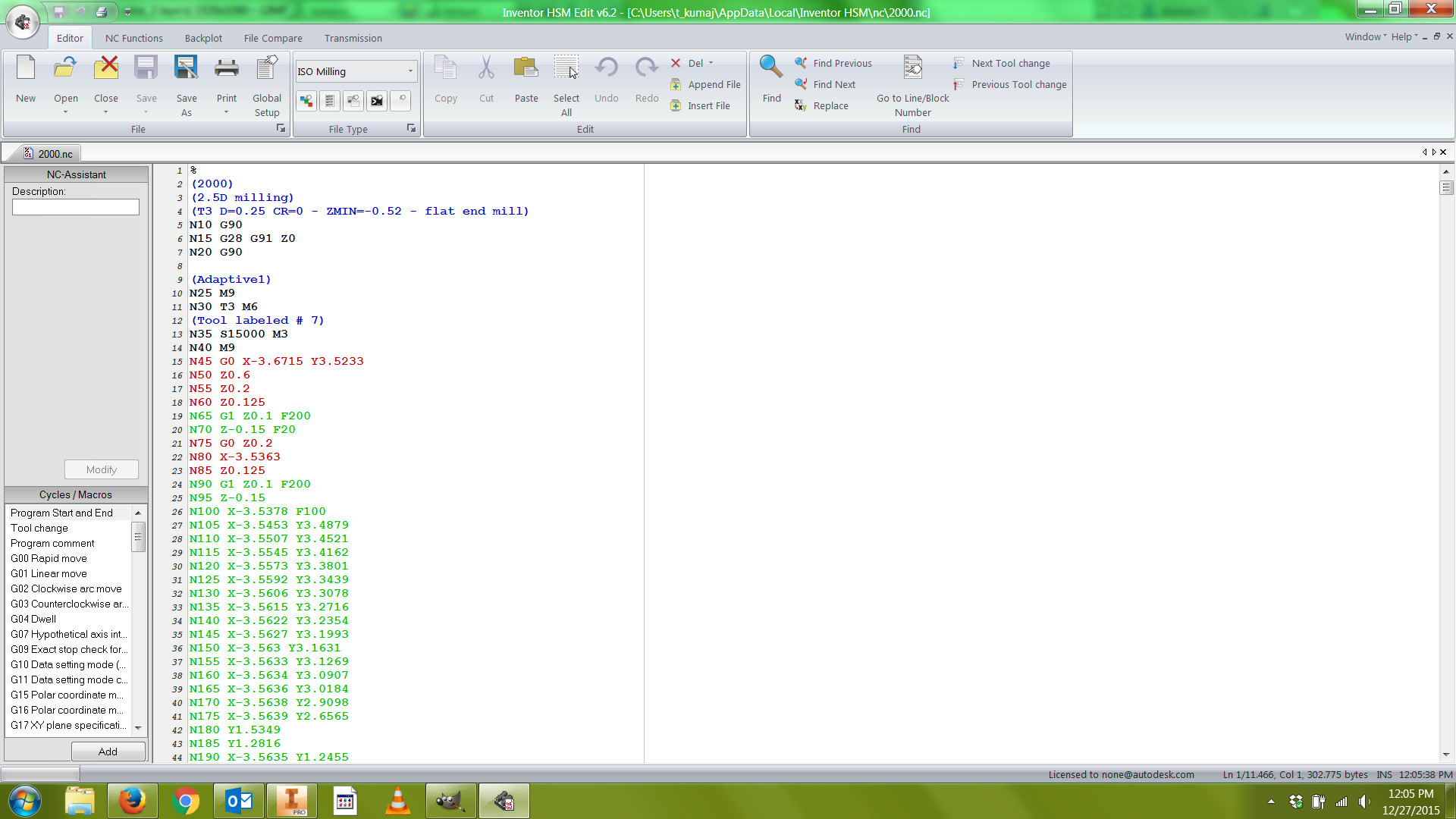
The final step is to post process, which will convert the toolpaths in your Setup into an alphanumeric program in a computer language called G-code. These are the instructions your Shopbot will use to machine your part.
1) Right click Setup, and choose Post process.
2) Click Setup in the top right of the new popup box, and choose "Generic."
3) In Post Configuration, choose shopbot.cps (Shopbot Open SBP).
4) Choose any output folder you want. This could be a folder on your desktop, or a USB to bring your program right to the machine.
5) Choose a four-digit number for your program name, and write this down in a notebook with a clear label.
6) Write a specific Program comment, which could include the date. This will appear in the G-code under the program name, helping you verify which program you're using.
7) Click Post. The program will appear in the Inventor editor, and it will be saved in your output folder.
8) Your program will save as a .sbp file, like 1001.sbp.
9) Now you're ready to bring your program to the Shopbot!
Remember that once you start operating the Shopbot, you should perform a dry run in the air to verify your program before you start to cut your part.
For your reference, a comprehensive guide to learning CNC is Dan Vidakovich's great Instructable:
Beginniner and Advanced CAM.
Have fun!