Auto - Lamp
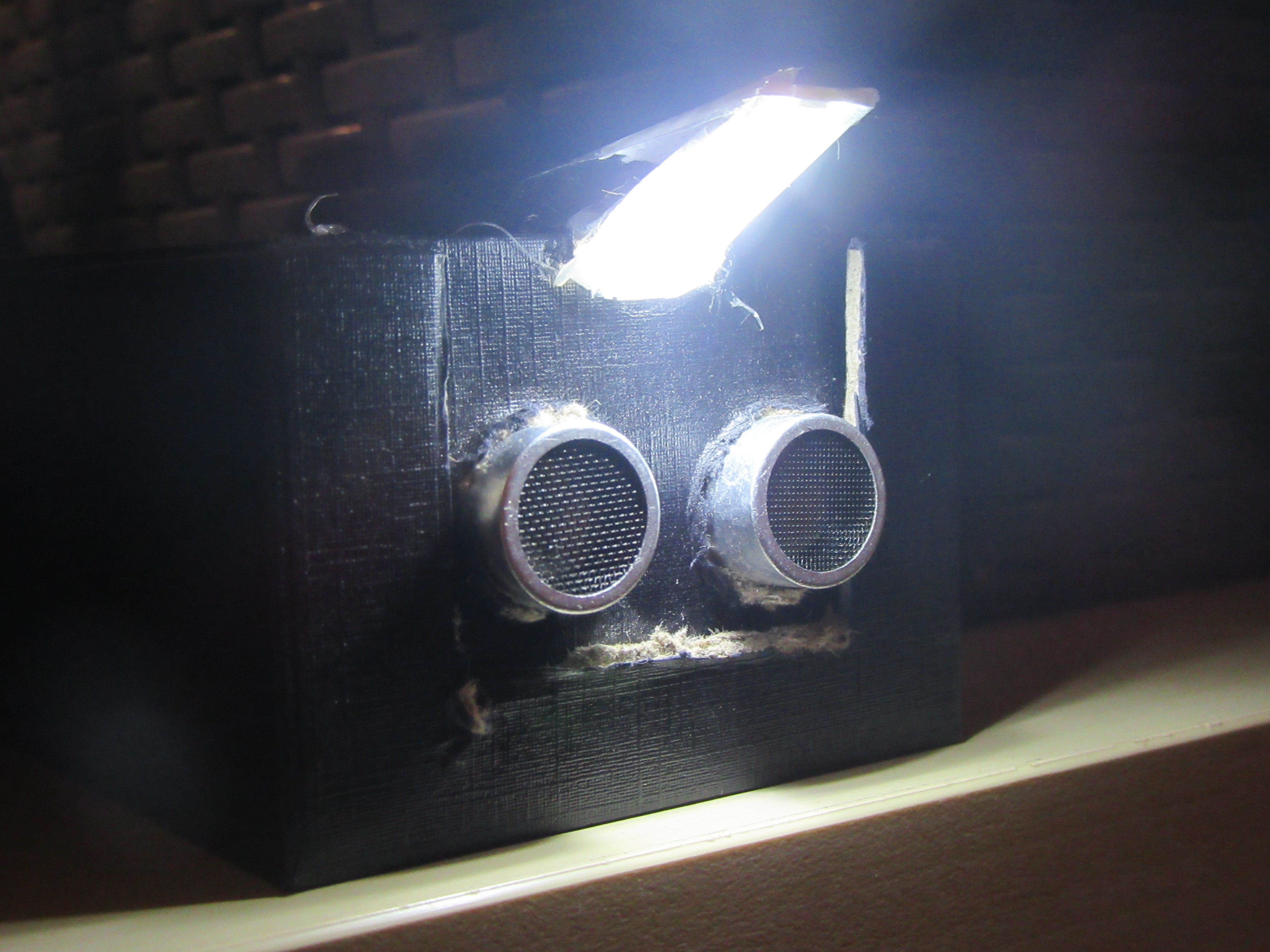
I have a book shelf in the corner of the room. The area is not lit, and I do not like to turn the light on and off every time I want to take a book.
With some basic components and simple code, you can also make a lamp that will automatically light up when you need it, and turn off when you don't need it.
For this project I used an arduino nano board.
The lamp has 2 sensors: ultrasonic distance sensor and light sensor (LDR).
The ultrasonic sensor alerts the microcontroller when a person approaches the lamp - so it should turn on. The LDR sensor checks if the room is already lit - when there is already enough light in the room, the lamp will not light even when approaching.
The lamp will turn itself off alone if for some time no one passes by it.
Arrange All Components
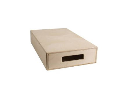
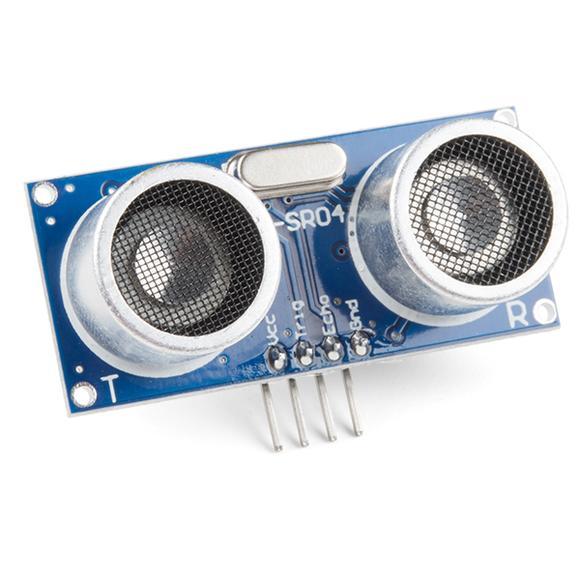
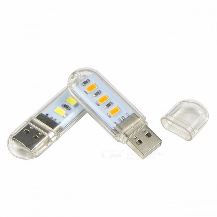
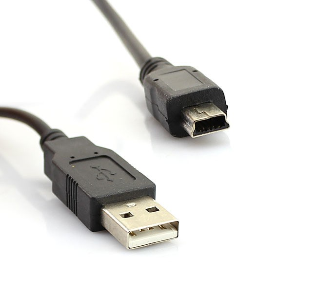
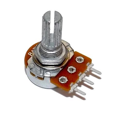
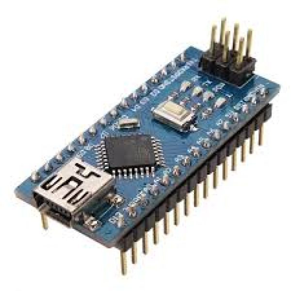
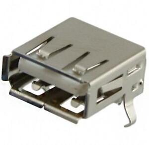
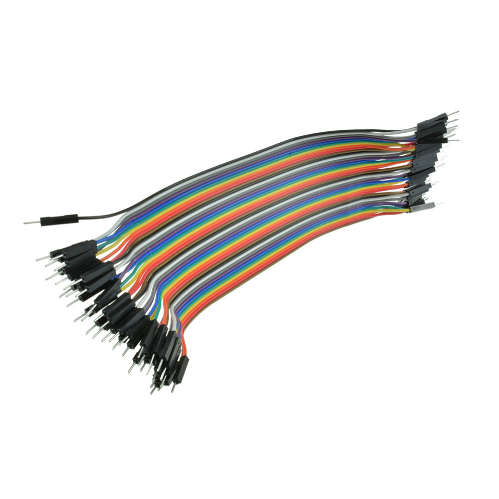
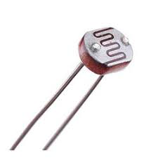
These are the components used in construction:
- Ultrasonic sensor (Amazon)
- Arduino board (No matter what kind, I chose Nano because of its size) (Amazon)
- USB socket (female) - not required, but better to have. (Amazon)
- USB cable that fits the Arduino board
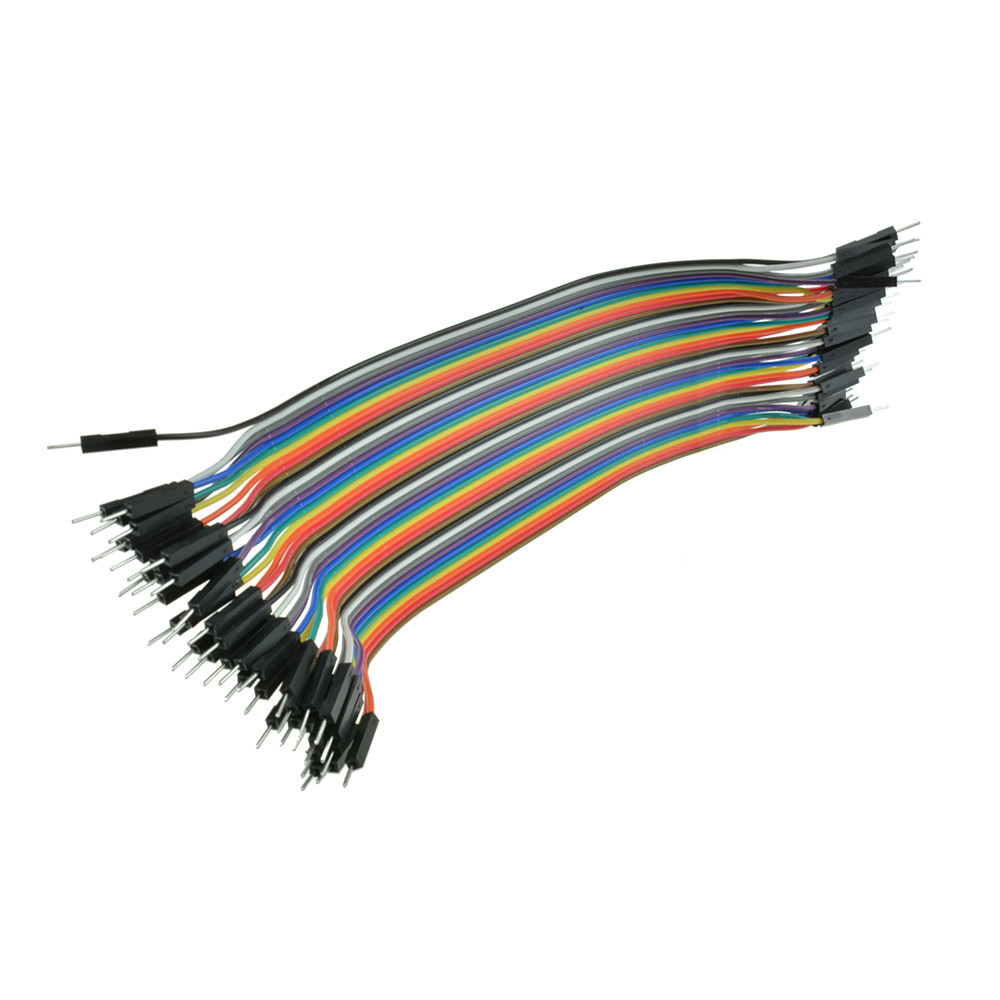
- Wiring wires - a few male-female and a few male-male. (Amazon)
- USB powered lamp (Amazon)
- Resistor - 10KΩ is good
- an LDR (Amazon)
- Potentiometer (Amazon)
- Small cardboard box - all components will be inserted into it
Tools to use in construction:
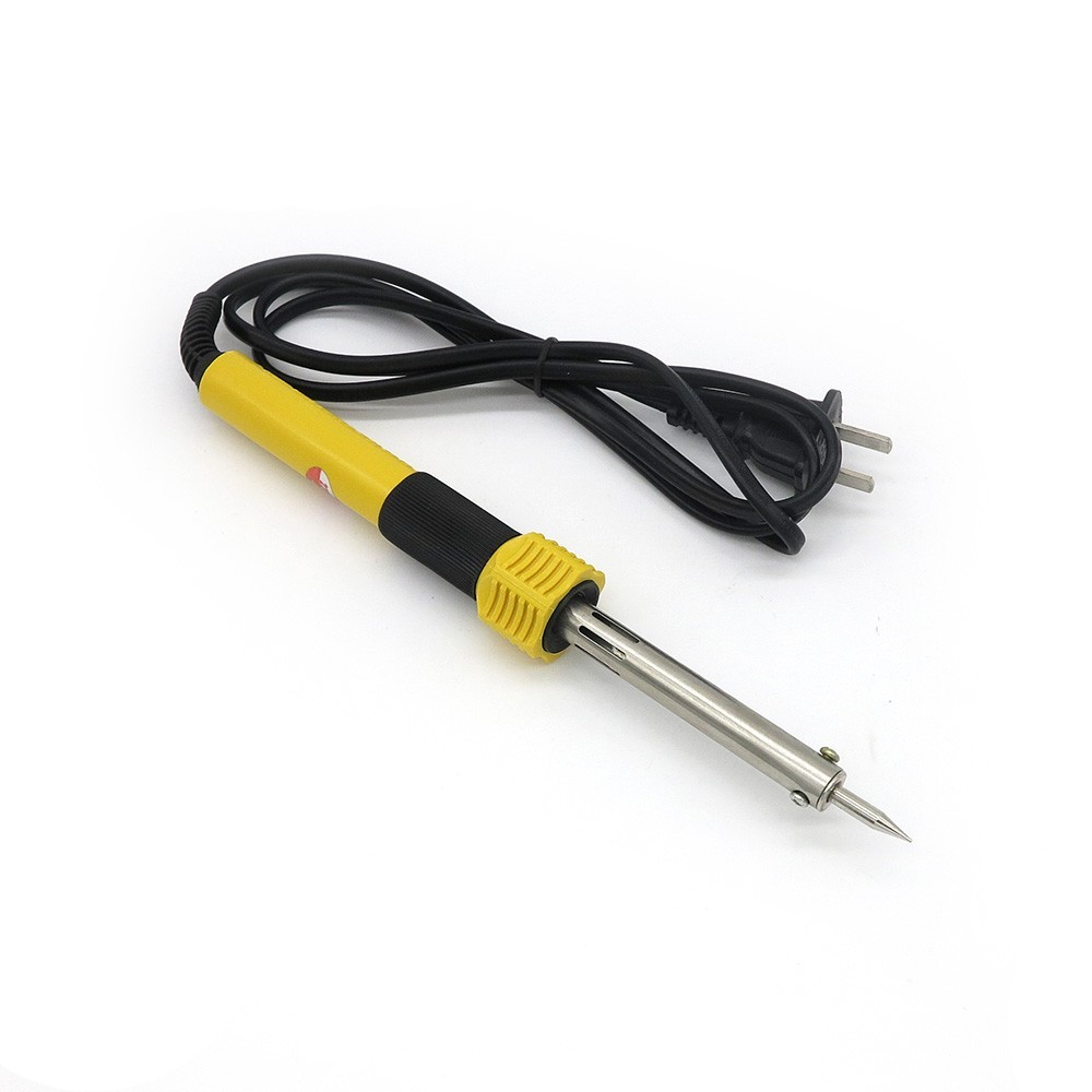
- Soldering iron + tin
- Glue gun
- utility knife
If you have all of this, you can start!
Make Holes in the Box
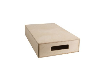
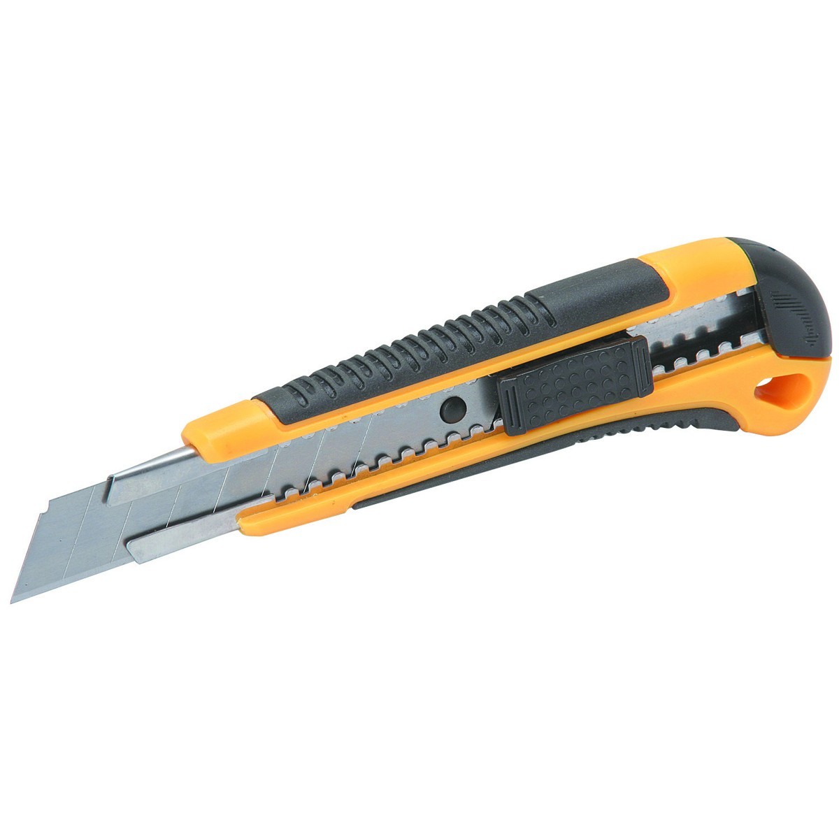
Place the ultrasonic sensor on the box and mark its "eyes" with the pen.
Using the utility knife, cut 2 holes in the box so that you can insert the "eyes" of the ulltrasonic sensor through the cardboard.
With a needle, pierce 2 small holes at the top of the box, through which you will thread the LDR threads later.
Cut a hole the size of the USB connection at the front / top of the box.
In the back - make a hole so you can pass the USB cable through it to the microcontroller.
Wiring
First, hread the LDR legs through the holes you made in the previous step.
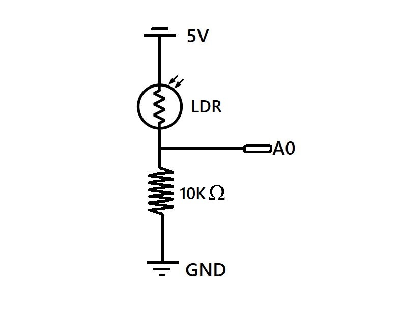
Weld one leg of the LDR to one leg of the resistor. At the same place, weld a male-male thread, as in the picture.
The male-female thread is added to the second leg of the LDR, and one is added to the other leg of the resistor.
Insert the wire connected to the GND pin on the Arduino board, the wire connected to the LDR plug to 5V, and the wire connected to both of them to A0.
This will create a voltage-drop on the resistor, so that there is more light in the room - the higher the voltage we get from the common wire.
Take 3 male-female wires, connect them to the legs of the potentiometer. Connect the two outer legs - one to 5 V and one to GND, the middle leg to the A1.
Take 4 male-female wires, then connect the legs of the ultrasonic sensor in this way:
- Gnd (sensor) > Gnd (arduino)
- Trig (sensor) > digital pin 4 (arduino)
- Echo (sensor) > digital pin 5 (arduino)
- Vcc (sensor) > 5V (arduino)
Weld 2 male threads to the 2 external legs of the USB jack.
Connect one of them to the GND and the other of pin 6. You will know which one to connect to which pin after you perform the following test:
Try connecting one of them to GND and one to 5V, and plug the lamp into the USB jack. If it does not light up - turn the wires from GND to 5V and vice versa. When the lamp comes on - move the wire from the 5V pin and put it in the 6 digital pin.
Set the Potentiometer & Coding

Download the attached code and upload it to the arduino.
Put the board where you consider 'dark'.
Open the serial monitor (ctrl + M) - You will see 2 printed numbers repeatedly. Adjust the potentiometer until both numbers are about equal.
Download the code from github.com.
Open the 'AutoLamp.ino' file and upload it to the arduino. (You need to extract the files first).
Downloads
Glueing
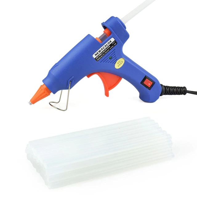
Insert all components into the box.
Put the ultrasonic sensor in the front, inside the holes you cut, and glue it into place with the glue gun.
Glue the LDR into place, but do not cover it.
Glue the USB socket next to the hole you made for it so that it is facing out.
Pass the USB cable through the hole you made for it, and glue it so it wouldn't move.
Close and glue the box so it wouldn't opened.
Finish!
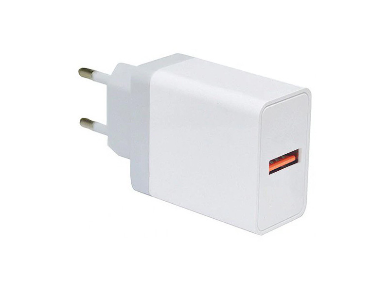

Connect the cable to a USB charger and put the box in the dark. Connect the lamp to the USB socket.
that's it! Now when you pass in front of her the lamp will light.
If you do not pass in front of her for a while, she will turn off alone.